EP0138477A1 - Improved reactor internals hold down spring - Google Patents
Improved reactor internals hold down spring Download PDFInfo
- Publication number
- EP0138477A1 EP0138477A1 EP84306626A EP84306626A EP0138477A1 EP 0138477 A1 EP0138477 A1 EP 0138477A1 EP 84306626 A EP84306626 A EP 84306626A EP 84306626 A EP84306626 A EP 84306626A EP 0138477 A1 EP0138477 A1 EP 0138477A1
- Authority
- EP
- European Patent Office
- Prior art keywords
- flange
- spring
- pressure vessel
- internals
- coolant
- Prior art date
- Legal status (The legal status is an assumption and is not a legal conclusion. Google has not performed a legal analysis and makes no representation as to the accuracy of the status listed.)
- Granted
Links
Images


Classifications
-
- G—PHYSICS
- G21—NUCLEAR PHYSICS; NUCLEAR ENGINEERING
- G21C—NUCLEAR REACTORS
- G21C13/00—Pressure vessels; Containment vessels; Containment in general
- G21C13/02—Details
-
- G—PHYSICS
- G21—NUCLEAR PHYSICS; NUCLEAR ENGINEERING
- G21C—NUCLEAR REACTORS
- G21C15/00—Cooling arrangements within the pressure vessel containing the core; Selection of specific coolants
- G21C15/22—Structural association of coolant tubes with headers
-
- Y—GENERAL TAGGING OF NEW TECHNOLOGICAL DEVELOPMENTS; GENERAL TAGGING OF CROSS-SECTIONAL TECHNOLOGIES SPANNING OVER SEVERAL SECTIONS OF THE IPC; TECHNICAL SUBJECTS COVERED BY FORMER USPC CROSS-REFERENCE ART COLLECTIONS [XRACs] AND DIGESTS
- Y02—TECHNOLOGIES OR APPLICATIONS FOR MITIGATION OR ADAPTATION AGAINST CLIMATE CHANGE
- Y02E—REDUCTION OF GREENHOUSE GAS [GHG] EMISSIONS, RELATED TO ENERGY GENERATION, TRANSMISSION OR DISTRIBUTION
- Y02E30/00—Energy generation of nuclear origin
- Y02E30/30—Nuclear fission reactors
Definitions
- the present invention relates to a reactor pressure vessel with hold-down springs for holding nuclear reactor internals firmly in place and more particularly to Belleville type spring assemblies for clamping upper and lower reactor internals inside of a reactor vessel while providing a coolant flow path to the reactor vessel head region.
- Nuclear reactor cores are usually supported within a cylindrical core barrel arranged within a reactor vessel as a liner and hung from a flange formed where the reactor vessel and reactor vessel head are joined.
- the core and core barrel are commonly referred to as the lower internals. Coolant flows into the reactor vessel into an inlet annulus and is directed towards the bottom of the core barrel and then up through the core. During operation, the coolant is heated by the core. The heated coolant is then discharged from the reactor vessel as working fluid.
- a large pressure differential exists across the core which results in a very large lifting force against the core. This force actually tends to displace the core _and its supporting structure.
- the upper internals Positioned above the core in the pressure vessel are components known as the upper internals through which the heated coolant may pass before exiting from the pressure vessel.
- the upper internals are usually contained in a second cylindrical barrel axially aligned above the core barrel. The heated coolant, when passing through the upper internals, exerts a very considerable force against those components as well.
- the prior large spring designs further comprise a 360° structure which requires a complex system of flow passages in order to permit passage of inlet coolant to the upper head region. It should be understood that flow rates of up to 60,000 1/min. (or on the order of 4% of the inlet flow) have to be accommodated.
- U.S. Patent No. 4,096,034 Disclosed in U.S. Patent No. 4,096,034 is a structure for clamping a core barrel and upper internals band against hydraulic displacement by using a few large Belleville springs mounted in vertical alignment with the wall of the upper internals barrel.
- a nuclear reactor pressure vessel assembly comprising a reactor pressure vessel; a lower internals assembly disposed within the reactor pressure vessel including a core barrel having a flange and an upper internals assembly positioned within the reactor pressure vessel including an upper internals barrel having a flange, axially disposed above said core barrel flange characterized in that a plurality of first and second angularly spaced coolant passages extend through the flanges of said core barrel and said upper internals barrel and a plurality of reactor internals Belleville type hold down spring assemblies are arranged angularly spaced about said core barrel flange and disposed between said core barrel and upper internals barrel flanges between said first and second coolant passages, and that a retainer extends through each of said spring assemblies for retaining said assemblies, said retainer having a central bore and extending between said first and second coolant passages for defining a connecting flow passage therebetween.
- the core barrel and pressure vessel form an inlet coolant flow annulus in fluid communication with the coolant passages in the core barrel.
- the upper internals barrel and pressure vessel form an upper head region in fluid communication with the coolant passages in the upper internals barrel. In this manner, coolant from the inlet annulus flows through the core barrel coolant passages, the connecting flow passages, the upper internals barrel coolant passages, and to the upper head region of the reactor.
- the means defining the connecting coolant passage may comprise a bellows flange having an opening and fixed at one end of the central bore with a spring bellows carried by the bellows flange and disposed within the central bore and movable plunger having a central opening carried by the spring bellows, the plunger being adopted to be biased against one of the core barrel coolant passages by the spring bellows.
- the retainer has an upper flange, adapted to seat against the upper internals flange, the upper flange being dimensioned to retain the stack of Belleville springs on the retainer when the stack is seated against the core barrel flange to resiliently support the upper internals barrel.
- the plunger has a generally spherical end portion and the core barrel coolant passages have cone shaped seating surfaces.
- the spherical ends are biased against the seating surfaces by the bellows spring in order to effect a generally fluid tight seal therebetween.
- the upper bellows flange carries a central tube disposed within the spring bellows which extends toward but does not contact the plunger.
- the hold down. spring assemblies include a locking nut adapted to cooperate with the retainer to preload the stack of Belleville springs.
- the means defining a connecting coolant passage preferably comprises a first movable plunger which has a central opening and is movably retained within one end of the central bore and a second movable plunger having a central opening and which is movable within another end of the central bore.
- a spring bellows is disposed between the first and second plungers and within the central bore in order to bias the first and second plungers against the upper internals barrel and core barrel coolant passages respectively.
- a nuclear reactor pressure vessel assembly 100 comprising a reactor pressure vessel 102 which, in the illustrated embodiment, is a generally cylindrically shaped vessel closed at one end by a generally hemispherically shaped end portion 104.
- the vessel 102 has a coolant inlet 106 and a coolant outlet 108 formed therein to circulate coolant through the vessel.
- the top end of the vessel 102 is closed by a reactor pressure vessel head 110 which sits on a flange portion 112 of the vessel 102.
- a lower internals assembly 114 is supported within the vessel 102 and hung from the flange 112.
- the lower internals assembly comprises a perforated lower core support plate 116 and a perforated upper core support plate 118.
- the lower internals are used to support an array of fuel rod assemblies 120, two of which are illustrated in Figure 1 by way of example.
- the upper internals assembly 122 Positioned axially above the lower internals assembly 114 in the reactor pressure vessel 102 is the upper internals assembly 122.
- the upper internals assembly is generally disposed within the core barrel 124 of the lower internals assembly 114 and also hung from the flange 112.
- the upper internals assembly 122 comprises a hat- shaped upper internals top plate 126 and a perforated upper internals barrel 128 disposed within the core barrel 124 and forming an annulus 127 therewith.
- the upper internals assembly 122 contains a plurality of control rod guide structure assemblies 130, only two of which are illustrated for clarity.
- the guide structure assemblies pass through the upper internals top plate forming an annulus therewith through which coolant in the upper head region 132 can pass into the upper internals.
- Coolant flows into the reactor pressure vessel through the coolant inlet 106. Most of the coolant flows through the inlet annulus 134 and towards the bottom region 136 of the vessel. The coolant then flows up through the perforated lower core support plate 116 and is heated to working temperatures while passing through the lower internals. The coolant then flows through the upper internals, the perforated upper internals barrel and out through the coolant outlet 108.
- the coolant flowing into the head region 132 serves the important safety function of maintaining the control rod drive mechanism components which pass through the upper head region at coolant inlet temperatures.
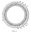
- FIG. 2 there is illustrated a sectional view of the pressure vessel of Figure 1 omitting the reactor internal details for clarity.
- a plurality of stud holes are axially spaced about the pressure vessel flange 112 for accommodating stud bolts or the like used to fasten the pressure vessel head 110 to the pressure vessel 102.
- a series of alignment keys slots 142 are formed in the core barrel.
- the alignment keys slots are rectangular in shape and each is operable to accommodate a key member 140 (Figure 1) in order to at least grossly align the core barrel 124 and the pressure vessel 102.
- a plurality of Belleville spring assemblies 138 are angularly spaced about the flange 144 of the core barrel 124.
- Each of the assemblies 138 which are described in detail below, are relatively small and have a large deflection capability. Consequently, they require less precision in design and manufacture than a single large Belleville spring or a few large spring assemblies.
- the small Belleville spring assemblies 138 are easily replaced when necessary and can be easily handled, inspected and decontaminated.
- the small hold down spring assemblies 138 represent a significant cost savings, both in terms of reactor construction and maintenance, over prior art spring assemblies.
- a plurality of shim members 146 are provided to limit the amount of travel of the upper internals band with regard to the core barrel.
- the Belleville washer assemblies 138 are positioned on a flange 144 of the core barrel 124 and the shims 146 are dimensioned to prevent the spring assemblies from over deflection or collapse in case of a seismic event or the like by limiting the maximum allowable deflection of the Belleville spring assemblies 138.
- FIG 3 there is depicted in greater detail a section of the reactor vessel assembly of Figure 1 in the vicinity of a Belleville spring assembly 138 indicating reactor coolant flow directions. All upper internals components are omitted for clarity.
- the core barrel 124 has a flange 144 that sits on a ledge 150 formed along the inside circumference of the reactor vessel 102.
- a coolant flow passage 152 is formed through the core barrel flange at the site of the Belleville spring 138.
- the upper internals barrel 128 includes flange 154 which is dimensioned to sit axially above the core barrel flange 144.
- the flange 154 has a plurality of coolant passages 156 angularly spaced to align with the passages 152 when the core barrel and upper internals barrel are assembled in the pressure vessel.
- each Belleville spring assembly is disposed between the upper internals barrel flange 154 and core barrel flange 144 and has a connecting coolant flow passage 158 aligned with the passages 152 and 156, thus providing a continuous passage for inlet coolant in the annular 134 to flow into the upper head region 132 via an upper head annulus 131 and then through a small annulus formed in the drive rod hole 160 when the drive rod mechanism (not illustrated) is in place.
- the upper internals barrel 128 is resiliently supported above and in coaxial alignment with the core barrel 114 by the angularly spaced plurality of Belleville spring assemblies 138 and alignment keys 140.
- Each spring assembly 138 comprises means for carrying a stack of Belleville springs.
- Such means may comprise a central retainer 162, preferably having an upper flange 164 which seats against the upper internals barrel flange 154. Grooves 166 may be cut into the sealing surface 168 of the flange 164 to improve the seal with the flange 154.
- the lower portion 170 of the retainer 162 is formed with a tapped length of reduced diameter for accommodating locking nut 172 which is used during the assembly of the hold down spring assembly 138 to preload the springs.
- a locking pin 174 or other similar fastening device is used to arrest the locking nut 172 on the central retainer 162.
- Belleville springs 176 are stacked vertically on the retainer 162.
- the Belleville springs may be stacked as single layers of opposing spring disks of alternating angular orientation or may be arranged in alternating and opposing groups of two or more spring disks of the same angular orientation.
- a spring assembly is built up which, after assembly, bears against generally flat inner flange surface 178 of the retainer 162 and against the locking 172 with a set preload. If the retainer 162 is fabricated without a flange 164, an external snap ring or the like may be used to retain the spring disks.
- the assembly comprises a stack of nine spring disks which, when compressed, exert a force of on the order of 9,000 kg.
- a means defining the connecting coolant passage 158 which comprises a bellows flange 182, a spring bellows 184 and a plunger 186.
- the bellows flange 182 seats against a shoulder 188 formed in the bore 180.
- a snap ring 190 or similar fastener holds the bellows flange in place in the bore 180.
- the bellows flange and plunger are provided with shoulders 192 and 194 respectively between which the spring bellows 184 is adapted to be retained.
- the compressed deflection of the spring assembly is typically in the range of about 1.2 to 2.5 cm. depending upon the specific design chosen. This deflection, which is several times that of a large single Belleville spring, provides protection against unloading due to stress relaxation. With the present invention, a small deformation due to relaxation produces a small change in spring force whereas with the large Belleville spring the same deformation produces a large reduction in loading.
- the difficulties in replacing a large Belleville spring were previously described.
- the small spring assemblies of the present invention weigh on the order of 50 pounds and are therefore easily handled. Decontamination and inspection of the small spring assembly is far easier and results in less man-rem exposure than is the case with large hold down springs.
- the core barrel cooling passage 152 is formed with a cone shaped seating surface 196 and the plunger 186 is formed with a spherical end which seats against the surface 196 in a generally fluid tight manner under a bias from the spring bellows 194.
- the plunger 186 has a bore 198 which aligns with a tube 200 extending from the bellows flange 182.
- the tube 200 is dimensioned to fit within an expanded diameter section 202 of the plunger bore 198 and to be sufficiently spaced from the plunger bore to allow for spring assembly deflection.
- the coolant flow path from the passage 152 to the passage 156 is through the seat 196, the plunger 186 and the bellows flange tube 200.
- the spring bellows biases the plunger against the seating surface 196 and prevents any coolant flow past the tube 200 from dispersing into the upper internals.
- basic design consists of employing multiple stacks of small Belleville springs arranged in a circle on the flange of the core barrel flange 144.
- the small Belleville springs have the configuration of a conical thick wall washer and are typically 7 to 10 inches in outside diameter with a center hole of 8.7 to 10 cm. diameter.
- Typically 5 to 10 small spring washers are stacked vertically and held together by the cylindrical retainer 162.
- the bore 180 in the center of the retainer provides space for the connecting flow passage generally 158 with its sealing and expansion accommodating features.
- FIG. 5 there is illustrated a second embodiment of a Belleville spring assembly in accordance with the present invention.
- the only significant difference between the embodiments of Figures 4 and 5 is an upper plunger 204 is used in lieu of the bellows flange assembly 182 of Figure 4.
- the passage 156 is formed with a conical seating surface 206 similar to the surface 196 discussed above against which the generally spherical end 208 of the plunger 204 is biased by the spring bellows 184.
- the upper plunger 209 is formed with a retaining plate 210 which, after assembly, is restrained to move axially between the snap ring 190 and the shoulder 188 of the retainer 162.
- a flow passage is provided with improved sealing and expansion accommodation features.
- the connecting flow passage does not require leak tightness but it is desirable to minimize leakage between the coolant flow passage and the upper internals interior volume since such leakage will not contribute to head cooling and will reduce the reactor outlet temperature by dilution, and will add to the plant pumping lower load.
- the flow passage design of the spring assembly of either Figures 4 or 5 will achieve this goal.
- a single ball and cone seal 186, 196 is utilized at the bottom of the assembly. Leakage is limited at the top of the assembly by tight clearances between the retainer flange 168 and the upper internals barrel flange 154.
- the element is secured within the retainer by a snap ring.
- the embodiment of Figure 5 is similar except that ball and cone seats are furnished at both ends of the flow element to further reduce bypass leakage.
- a typical spring assembly may be compressed 1.2 to 2.5 cm. when it is installed for service. As a consequence the flow sealing arrangement must accommodate that movement.
- a single ply standard spring bellows 184 is preferably incorporated in the assembly to perform this function.
- the assemblies of the design of either Figures 4 or 5 provide a simple and inexpensive means for establishing and controlling a coolant flow to the pressure vessel head region 132. If it is desired to reduce the flow, members having reduced or valved bores can be inserted by removing the snap ring 190 and inserting an appropriately dimensioned element in lieu of the bellows flange 182 of Figure 4 or the upper plunger 204 of Figure 5.
- a hold-down spring assembly 138 is disclosed intended for use in a pressure vessel assembly in which the travel limiting shims 146 of Figure 2 have been omitted.
- the core barrel flange 144 has an increased axial thickness relative to the flanges of Figures 4 or 5 and the Belleville spring assemblies 138 are disposed in a generally cylindrically counter bore 204 formed in the flange 144 of the core barrel.
- This counter bore 204 has a shoulder 205 for supporting the Belleville spring stack.
- the flange not only supports the spring assemblies 138 but also functions to limit the maximum deflection of the assembly.
- the spring assemblies of Figure 6 are designed so that when the upper internals and core are loaded into the pressure vessel, the resulting deflection of the spring assemblies 138 produces a gap 206 between the flanges 154 and 144. If the springs are overloaded due to a seismic event or the like or due to stress relaxation, the maximum additional deflection is limited to a distance equal to the gap 206 after which the flanges 144 and 154 abut one another.
- the gap 206 is typically on the order of about 1.5 to 2.3 mm.
- Other elements of Figure 6 are similar to the assemblies of Figures 4 and 5 and are not further described in detail.
- the spring assemblies of the present invention are relatively small and have a large deflection capability.
- the Belleville spring assemblies disclosed require less precise design and less manufacturing precision than a single or a few large spring assemblies. Consequently, the present invention can provide the required spring load and defLection capability at lower cost, afford easier replacement, handling, inspection and decontamination.
- the present spring assembly design provides a generally fluid tight flow path for upper head cooling using a flow passage which is easily replaceable and adjustable to change the reactor head cooling flow rate.
- the present small spring assemblies can be load tested before installation which is almost impossible with very large spring assemblies.
- the small diameter of the spring assemblies reduces the required reactor flange diameter by 11 cm. or more with a consequent savings of some 12,000 kg. or more in reactor vessel weight.
Abstract
Description
- The present invention relates to a reactor pressure vessel with hold-down springs for holding nuclear reactor internals firmly in place and more particularly to Belleville type spring assemblies for clamping upper and lower reactor internals inside of a reactor vessel while providing a coolant flow path to the reactor vessel head region.
- Nuclear reactor cores are usually supported within a cylindrical core barrel arranged within a reactor vessel as a liner and hung from a flange formed where the reactor vessel and reactor vessel head are joined. The core and core barrel are commonly referred to as the lower internals. Coolant flows into the reactor vessel into an inlet annulus and is directed towards the bottom of the core barrel and then up through the core. During operation, the coolant is heated by the core. The heated coolant is then discharged from the reactor vessel as working fluid. Generally, a large pressure differential exists across the core which results in a very large lifting force against the core. This force actually tends to displace the core _and its supporting structure. Positioned above the core in the pressure vessel are components known as the upper internals through which the heated coolant may pass before exiting from the pressure vessel. The upper internals are usually contained in a second cylindrical barrel axially aligned above the core barrel. The heated coolant, when passing through the upper internals, exerts a very considerable force against those components as well.
- In most pressurized water reactor (PWR) constructions, the upper internals barrel is also supported from the flange formed where the reactor vessel and reactor vessel head are joined. Because of the large size of the structures involved and the significant thermal gradients which exist in the reactor vessel, axial and radial differential expansions occur at the assembly of the vessel and core components. Because of these differential expansions and the large mechanical and hydraulic forces discussed above which act on these structures, the assembly must provide a large enough force to resist displacement.
- In addition, it is desirable to maintain the reactor vessel head region at inlet temperatures for safety reasons and to cool the upper internals drive components. Such cooling could only be achieved with a complex system of flow passages with prior designs which utilized a single large Belleville spring to provide a spring load and deflection capability for holding core barrel and upper internals barrel against deflection.
- With a large Belleville spring, a clamping load is developed when the reactor vessel head is lowered onto the Belleville spring and drawn down by head studs onto the reactor vessel flange. The spring is typically deflected on the order of only about 3.8 mm. resulting in about 210,000 kg of force to clamp the upper and lower internals against a machined ledge on the inside of the reactor vessel flange. Such loading is sufficient to prevent significant upward motion of the internals during normal operation and during seismic or LOCA events.
- However, with large (in the range of 4 to 5 m. diameter) Belleville springs, the loading force is developed over a very short deflection and therefore requires considerable precision. Moreover, large precision machined springs are expensive, difficult to heat treat and, because of their size and shape, difficult to handle, ship and replace. Also, with large springs a high stress is developed in the spring over a relatively small deflection which renders its performance vulnerable to stress relaxation after which replacement may be required to maintain adequate loading forces. Replacement is difficult not only because the spring is large but also because it is typically coated with a radioactive crud. Moreover, the size of a single spring is such that the replacement spring must come through a large hatch in the reactor containment resulting in long down times for the reactor.
- The prior large spring designs further comprise a 360° structure which requires a complex system of flow passages in order to permit passage of inlet coolant to the upper head region. It should be understood that flow rates of up to 60,000 1/min. (or on the order of 4% of the inlet flow) have to be accommodated.
- Disclosed in U.S. Patent No. 4,096,034 is a structure for clamping a core barrel and upper internals band against hydraulic displacement by using a few large Belleville springs mounted in vertical alignment with the wall of the upper internals barrel.
- It is therefore an object of the present invention to provide a reactor vessel having an inexpensive, testable, and easily replaceable hold down structure for holding reactor internals which also permit passage of coolant to the upper reactor vessel region.
- With this object in view, the present invention resides in a nuclear reactor pressure vessel assembly comprising a reactor pressure vessel; a lower internals assembly disposed within the reactor pressure vessel including a core barrel having a flange and an upper internals assembly positioned within the reactor pressure vessel including an upper internals barrel having a flange, axially disposed above said core barrel flange characterized in that a plurality of first and second angularly spaced coolant passages extend through the flanges of said core barrel and said upper internals barrel and a plurality of reactor internals Belleville type hold down spring assemblies are arranged angularly spaced about said core barrel flange and disposed between said core barrel and upper internals barrel flanges between said first and second coolant passages, and that a retainer extends through each of said spring assemblies for retaining said assemblies, said retainer having a central bore and extending between said first and second coolant passages for defining a connecting flow passage therebetween.
- The core barrel and pressure vessel form an inlet coolant flow annulus in fluid communication with the coolant passages in the core barrel. The upper internals barrel and pressure vessel form an upper head region in fluid communication with the coolant passages in the upper internals barrel. In this manner, coolant from the inlet annulus flows through the core barrel coolant passages, the connecting flow passages, the upper internals barrel coolant passages, and to the upper head region of the reactor.
- Preferably, the means defining the connecting coolant passage may comprise a bellows flange having an opening and fixed at one end of the central bore with a spring bellows carried by the bellows flange and disposed within the central bore and movable plunger having a central opening carried by the spring bellows, the plunger being adopted to be biased against one of the core barrel coolant passages by the spring bellows.
- Preferably, the retainer has an upper flange, adapted to seat against the upper internals flange, the upper flange being dimensioned to retain the stack of Belleville springs on the retainer when the stack is seated against the core barrel flange to resiliently support the upper internals barrel.
- Preferably, the plunger has a generally spherical end portion and the core barrel coolant passages have cone shaped seating surfaces. The spherical ends are biased against the seating surfaces by the bellows spring in order to effect a generally fluid tight seal therebetween.
- Advantageously, the upper bellows flange carries a central tube disposed within the spring bellows which extends toward but does not contact the plunger.
- Advantageously, the hold down. spring assemblies include a locking nut adapted to cooperate with the retainer to preload the stack of Belleville springs.
- In another embodiment, the means defining a connecting coolant passage preferably comprises a first movable plunger which has a central opening and is movably retained within one end of the central bore and a second movable plunger having a central opening and which is movable within another end of the central bore. A spring bellows is disposed between the first and second plungers and within the central bore in order to bias the first and second plungers against the upper internals barrel and core barrel coolant passages respectively.
- The invention will become more readily apparent from the following description of preferred embodiments. thereof shown, by way of example only, in the accompanying drawings, wherein:
- Figure 1 is an elevation in section through a reactor vessel illustrating the coolant flow;
- Figure 2 is a section through section lines A-A of Figure 1, illustrating the hold down assembly layout;
- Figure 3 is a fragmentary section illustrating an enlarged portion of the reactor vessel of Figure 1 in the region surrounding the Belleville spring assembly;
- Figure 4 is a sectional view of a first embodiment of a Belleville spring assembly according to the present invention;
- Figure 5 is a sectional view of a second embodiment of a Belleville spring assembly according to the present invention;
- Figure 6 is a sectional view of a third embodiment of a Belleville spring assembly according to the present invention.
- Turning first to Figure 1, there is depicted a nuclear reactor pressure vessel assembly 100. The assembly' comprises a
reactor pressure vessel 102 which, in the illustrated embodiment, is a generally cylindrically shaped vessel closed at one end by a generally hemispherically shapedend portion 104. Thevessel 102 has acoolant inlet 106 and acoolant outlet 108 formed therein to circulate coolant through the vessel. As viewed in Figure 1, the top end of thevessel 102 is closed by a reactorpressure vessel head 110 which sits on aflange portion 112 of thevessel 102. - A
lower internals assembly 114 is supported within thevessel 102 and hung from theflange 112. The lower internals assembly comprises a perforated lower core support plate 116 and a perforated uppercore support plate 118. The lower internals are used to support an array offuel rod assemblies 120, two of which are illustrated in Figure 1 by way of example. - Positioned axially above the
lower internals assembly 114 in thereactor pressure vessel 102 is the upper internals assembly 122. The upper internals assembly is generally disposed within thecore barrel 124 of thelower internals assembly 114 and also hung from theflange 112. The upper internals assembly 122 comprises a hat- shaped upper internalstop plate 126 and a perforatedupper internals barrel 128 disposed within thecore barrel 124 and forming anannulus 127 therewith. As illustrated in Figure 1, the upper internals assembly 122 contains a plurality of control rod guide structure assemblies 130, only two of which are illustrated for clarity. The guide structure assemblies pass through the upper internals top plate forming an annulus therewith through which coolant in theupper head region 132 can pass into the upper internals. - Coolant flows into the reactor pressure vessel through the
coolant inlet 106. Most of the coolant flows through theinlet annulus 134 and towards thebottom region 136 of the vessel. The coolant then flows up through the perforated lower core support plate 116 and is heated to working temperatures while passing through the lower internals. The coolant then flows through the upper internals, the perforated upper internals barrel and out through thecoolant outlet 108. - As will be appreciated by the artisan, the rate of coolant flow in a large reactor is tremendous and the forces exerted by the coolant against the upper and lower internals structure as it flows therethrough tends to displace those structures causing vibrations and the like.
- A small portion of the coolant flows to the
upper head region 132 through theannulus 127 and acoolant flow passage 158, described in detail below, which is provided in theBelleville spring asssembly 138 of the present invention. The coolant flowing into thehead region 132 serves the important safety function of maintaining the control rod drive mechanism components which pass through the upper head region at coolant inlet temperatures. - Turning now to Figure 2 there is illustrated a sectional view of the pressure vessel of Figure 1 omitting the reactor internal details for clarity. As can be appreciated from Figure 2, a plurality of stud holes are axially spaced about the
pressure vessel flange 112 for accommodating stud bolts or the like used to fasten thepressure vessel head 110 to thepressure vessel 102. - A series of alignment keys slots 142 are formed in the core barrel. In the embodiment illustrated the alignment keys slots are rectangular in shape and each is operable to accommodate a key member 140 (Figure 1) in order to at least grossly align the
core barrel 124 and thepressure vessel 102. As will be appreciated from Figure 2, a plurality ofBelleville spring assemblies 138 are angularly spaced about theflange 144 of thecore barrel 124. Each of theassemblies 138, which are described in detail below, are relatively small and have a large deflection capability. Consequently, they require less precision in design and manufacture than a single large Belleville spring or a few large spring assemblies. Moreover, the smallBelleville spring assemblies 138 are easily replaced when necessary and can be easily handled, inspected and decontaminated. The small hold downspring assemblies 138 represent a significant cost savings, both in terms of reactor construction and maintenance, over prior art spring assemblies. - In the embodiment of Figure 2, a plurality of
shim members 146 are provided to limit the amount of travel of the upper internals band with regard to the core barrel. As clearly seen in Figure 2, theBelleville washer assemblies 138 are positioned on aflange 144 of thecore barrel 124 and theshims 146 are dimensioned to prevent the spring assemblies from over deflection or collapse in case of a seismic event or the like by limiting the maximum allowable deflection of theBelleville spring assemblies 138. - Turning now to Figure 3, there is depicted in greater detail a section of the reactor vessel assembly of Figure 1 in the vicinity of a
Belleville spring assembly 138 indicating reactor coolant flow directions. All upper internals components are omitted for clarity. Thecore barrel 124 has aflange 144 that sits on aledge 150 formed along the inside circumference of thereactor vessel 102. Acoolant flow passage 152 is formed through the core barrel flange at the site of theBelleville spring 138. Theupper internals barrel 128 includesflange 154 which is dimensioned to sit axially above thecore barrel flange 144. Theflange 154 has a plurality ofcoolant passages 156 angularly spaced to align with thepassages 152 when the core barrel and upper internals barrel are assembled in the pressure vessel. As best seen in Figure 3, each Belleville spring assembly is disposed between the upperinternals barrel flange 154 andcore barrel flange 144 and has a connectingcoolant flow passage 158 aligned with thepassages upper head region 132 via anupper head annulus 131 and then through a small annulus formed in the drive rod hole 160 when the drive rod mechanism (not illustrated) is in place. Theupper internals barrel 128 is resiliently supported above and in coaxial alignment with thecore barrel 114 by the angularly spaced plurality ofBelleville spring assemblies 138 andalignment keys 140. - Turning now to Figure 4, there is illustrated a first preferred embodiment of a Belleville spring assembly according to the present invention. Each
spring assembly 138 comprises means for carrying a stack of Belleville springs. Such means may comprise acentral retainer 162, preferably having anupper flange 164 which seats against the upperinternals barrel flange 154.Grooves 166 may be cut into the sealingsurface 168 of theflange 164 to improve the seal with theflange 154. Thelower portion 170 of theretainer 162 is formed with a tapped length of reduced diameter for accommodating lockingnut 172 which is used during the assembly of the hold downspring assembly 138 to preload the springs. A lockingpin 174 or other similar fastening device is used to arrest the lockingnut 172 on thecentral retainer 162. - Belleville springs 176 are stacked vertically on the
retainer 162. As illustrated in Figure 4, the Belleville springs may be stacked as single layers of opposing spring disks of alternating angular orientation or may be arranged in alternating and opposing groups of two or more spring disks of the same angular orientation. In either manner, a spring assembly is built up which, after assembly, bears against generally flatinner flange surface 178 of theretainer 162 and against the locking 172 with a set preload. If theretainer 162 is fabricated without aflange 164, an external snap ring or the like may be used to retain the spring disks. In the embodiment illustrated, the assembly comprises a stack of nine spring disks which, when compressed, exert a force of on the order of 9,000 kg. If, for example, fifty spring assemblies are mounted on thecore barrel flange 144, they will cumulatively exert a force of about 450,000 kg. against the upper internals which is sufficient to fix the internals in place during normal and accident conditions. The stack of Belleville springs sits in arecess 179 formed in theflange 144. Positioned within abore 180 of theretainer 162 is a means defining the connectingcoolant passage 158 which comprises abellows flange 182, a spring bellows 184 and aplunger 186. The bellows flange 182 seats against ashoulder 188 formed in thebore 180. Asnap ring 190 or similar fastener holds the bellows flange in place in thebore 180. The bellows flange and plunger are provided with shoulders 192 and 194 respectively between which the spring bellows 184 is adapted to be retained. The compressed deflection of the spring assembly is typically in the range of about 1.2 to 2.5 cm. depending upon the specific design chosen. This deflection, which is several times that of a large single Belleville spring, provides protection against unloading due to stress relaxation. With the present invention, a small deformation due to relaxation produces a small change in spring force whereas with the large Belleville spring the same deformation produces a large reduction in loading. - The difficulties in replacing a large Belleville spring were previously described. The small spring assemblies of the present invention weigh on the order of 50 pounds and are therefore easily handled. Decontamination and inspection of the small spring assembly is far easier and results in less man-rem exposure than is the case with large hold down springs.
- Preferably, the core
barrel cooling passage 152 is formed with a cone shapedseating surface 196 and theplunger 186 is formed with a spherical end which seats against thesurface 196 in a generally fluid tight manner under a bias from the spring bellows 194. Theplunger 186 has abore 198 which aligns with atube 200 extending from thebellows flange 182. Thetube 200 is dimensioned to fit within an expanded diameter section 202 of the plunger bore 198 and to be sufficiently spaced from the plunger bore to allow for spring assembly deflection. It will be appreciated that the coolant flow path from thepassage 152 to thepassage 156 is through theseat 196, theplunger 186 and thebellows flange tube 200. The spring bellows biases the plunger against theseating surface 196 and prevents any coolant flow past thetube 200 from dispersing into the upper internals. - Thus, basic design consists of employing multiple stacks of small Belleville springs arranged in a circle on the flange of the
core barrel flange 144. The small Belleville springs have the configuration of a conical thick wall washer and are typically 7 to 10 inches in outside diameter with a center hole of 8.7 to 10 cm. diameter. Typically 5 to 10 small spring washers are stacked vertically and held together by thecylindrical retainer 162. Thebore 180 in the center of the retainer provides space for the connecting flow passage generally 158 with its sealing and expansion accommodating features. - Turning now to Figure 5 there is illustrated a second embodiment of a Belleville spring assembly in accordance with the present invention. The only significant difference between the embodiments of Figures 4 and 5 is an
upper plunger 204 is used in lieu of thebellows flange assembly 182 of Figure 4. Thepassage 156 is formed with aconical seating surface 206 similar to thesurface 196 discussed above against which the generallyspherical end 208 of theplunger 204 is biased by the spring bellows 184. The upper plunger 209 is formed with a retaining plate 210 which, after assembly, is restrained to move axially between thesnap ring 190 and theshoulder 188 of theretainer 162. Thus, a flow passage is provided with improved sealing and expansion accommodation features. The connecting flow passage, generally 158, does not require leak tightness but it is desirable to minimize leakage between the coolant flow passage and the upper internals interior volume since such leakage will not contribute to head cooling and will reduce the reactor outlet temperature by dilution, and will add to the plant pumping lower load. The flow passage design of the spring assembly of either Figures 4 or 5 will achieve this goal. In the embodiment of Figure 4, a single ball andcone seal retainer flange 168 and the upperinternals barrel flange 154. The element is secured within the retainer by a snap ring. The embodiment of Figure 5 is similar except that ball and cone seats are furnished at both ends of the flow element to further reduce bypass leakage. - As alluded to above, a typical spring assembly may be compressed 1.2 to 2.5 cm. when it is installed for service. As a consequence the flow sealing arrangement must accommodate that movement. A single ply standard spring bellows 184 is preferably incorporated in the assembly to perform this function. The assemblies of the design of either Figures 4 or 5 provide a simple and inexpensive means for establishing and controlling a coolant flow to the pressure
vessel head region 132. If it is desired to reduce the flow, members having reduced or valved bores can be inserted by removing thesnap ring 190 and inserting an appropriately dimensioned element in lieu of the bellows flange 182 of Figure 4 or theupper plunger 204 of Figure 5. - In a third embodiment of the invention, illustrated in Figure 6, a hold-down
spring assembly 138 is disclosed intended for use in a pressure vessel assembly in which thetravel limiting shims 146 of Figure 2 have been omitted. In the embodiment of Figure 6, thecore barrel flange 144 has an increased axial thickness relative to the flanges of Figures 4 or 5 and theBelleville spring assemblies 138 are disposed in a generally cylindrically counter bore 204 formed in theflange 144 of the core barrel. This counter bore 204 has ashoulder 205 for supporting the Belleville spring stack. In this embodiment the flange not only supports thespring assemblies 138 but also functions to limit the maximum deflection of the assembly. - The spring assemblies of Figure 6 are designed so that when the upper internals and core are loaded into the pressure vessel, the resulting deflection of the
spring assemblies 138 produces agap 206 between theflanges gap 206 after which theflanges gap 206 is typically on the order of about 1.5 to 2.3 mm. Other elements of Figure 6 are similar to the assemblies of Figures 4 and 5 and are not further described in detail. - As should now be appreciated, the spring assemblies of the present invention are relatively small and have a large deflection capability. In addition, the Belleville spring assemblies disclosed require less precise design and less manufacturing precision than a single or a few large spring assemblies. Consequently, the present invention can provide the required spring load and defLection capability at lower cost, afford easier replacement, handling, inspection and decontamination.
- In addition, multiple small spring assemblies provide a degree of redundancy which tolerates some assembly failures. Moreover, the present spring assembly design provides a generally fluid tight flow path for upper head cooling using a flow passage which is easily replaceable and adjustable to change the reactor head cooling flow rate. Importantly, the present small spring assemblies can be load tested before installation which is almost impossible with very large spring assemblies. In addition, the small diameter of the spring assemblies reduces the required reactor flange diameter by 11 cm. or more with a consequent savings of some 12,000 kg. or more in reactor vessel weight.
- The foregoing description of the preferred embodiments of the invention have been presented for purposes of illustration and description. They are not intended to be exhaustive or to limit the invention to the precise form disclosed, and obviously many modifications and variations are possible in light of the above teaching. For example, the size and shape of the spring stacks, the various retaining means, and type of coolant passage connections used may be modified within the spirit and scope of the invention. It is intended that the scope of the invention be defined by the claims appended hereto.
Claims (6)
Applications Claiming Priority (2)
| Application Number | Priority Date | Filing Date | Title |
|---|---|---|---|
| US538040 | 1983-09-30 | ||
| US06/538,040 US4786461A (en) | 1983-09-30 | 1983-09-30 | Reactor internals hold down spring |
Publications (2)
| Publication Number | Publication Date |
|---|---|
| EP0138477A1 true EP0138477A1 (en) | 1985-04-24 |
| EP0138477B1 EP0138477B1 (en) | 1988-06-22 |
Family
ID=24145181
Family Applications (1)
| Application Number | Title | Priority Date | Filing Date |
|---|---|---|---|
| EP84306626A Expired EP0138477B1 (en) | 1983-09-30 | 1984-09-28 | Improved reactor internals hold down spring |
Country Status (7)
| Country | Link |
|---|---|
| US (1) | US4786461A (en) |
| EP (1) | EP0138477B1 (en) |
| JP (1) | JPS6093993A (en) |
| KR (1) | KR850002358A (en) |
| DE (1) | DE3472326D1 (en) |
| ES (1) | ES8607600A1 (en) |
| GB (1) | GB2147449B (en) |
Cited By (4)
| Publication number | Priority date | Publication date | Assignee | Title |
|---|---|---|---|---|
| FR2654545A1 (en) * | 1989-11-15 | 1991-05-17 | Framatome Sa | DEVICE FOR SETTING THE UPPER PLATE FOR SUPPORTING THE CLUSTER GUIDES IN RELATION TO THE TANK OF A NUCLEAR REACTOR. |
| FR2696576A1 (en) * | 1992-10-05 | 1994-04-08 | Framatome Sa | Internal nuclear reactor equipment with spacer columns and control cluster guides. |
| WO1994011881A1 (en) * | 1992-11-10 | 1994-05-26 | Siemens Aktiengesellschaft | Arrangement for clamping a reactor shaft arranged in a reactor pressure vessel |
| FR2703180A1 (en) * | 1993-03-22 | 1994-09-30 | Westinghouse Electric Corp | Set of core shell and pressurized water nuclear reactor support plate. |
Families Citing this family (8)
| Publication number | Priority date | Publication date | Assignee | Title |
|---|---|---|---|---|
| US5605361A (en) * | 1994-05-06 | 1997-02-25 | Entergy Operations, Inc. | Replacement nozzle for pressure vessels and method of a attaching same |
| JP2978732B2 (en) * | 1994-12-12 | 1999-11-15 | 核燃料サイクル開発機構 | Common floor type vertical seismic isolation structure for reactor equipment |
| DE19852567C2 (en) * | 1998-11-13 | 2000-12-07 | Siemens Ag | Reactor pressure vessel and method for temperature compensation in a reactor pressure vessel |
| EP1448338B1 (en) | 2001-11-30 | 2009-12-23 | Westinghouse Electric Company LLC | Method of closing a pressure vessel |
| US6888909B2 (en) * | 2002-05-03 | 2005-05-03 | Westinghouse Electric Company Llc | Reactor pressure vessel |
| US6672260B1 (en) | 2003-03-26 | 2004-01-06 | Babcock & Wilcox Canada Ltd. | Steam generator tube support plates with slotted disc springs |
| DE102005037589B4 (en) * | 2005-08-05 | 2009-02-05 | Areva Np Gmbh | Cover element for the reactor core of a nuclear facility and nuclear reactor |
| CN108766593A (en) * | 2018-07-20 | 2018-11-06 | 中广核研究院有限公司 | A kind of in-pile component structure of reactor pressure vessel |
Citations (4)
| Publication number | Priority date | Publication date | Assignee | Title |
|---|---|---|---|---|
| US4096034A (en) * | 1976-12-16 | 1978-06-20 | Combustion Engineering, Inc. | Holddown structure for a nuclear reactor core |
| US4100019A (en) * | 1975-06-27 | 1978-07-11 | The United States Of America As Represented By The United States Department Of Energy | Nozzle seal |
| FR2407384A1 (en) * | 1977-10-26 | 1979-05-25 | Kraftwerk Union Ag | STOPPING DEVICE FOR MULTI-SOCKET PAN-HEAD SCREWS AND TOOL FOR PLASTICALLY DEFORMING SUCH A DEVICE |
| EP0094326A1 (en) * | 1982-05-12 | 1983-11-16 | Novatome | Apparatus fixation device in a nuclear reactor |
Family Cites Families (4)
| Publication number | Priority date | Publication date | Assignee | Title |
|---|---|---|---|---|
| US3070527A (en) * | 1958-04-29 | 1962-12-25 | Walter J Hurford | Composite fuel element |
| BE586969A (en) * | 1959-01-29 | |||
| US4096023A (en) * | 1976-05-06 | 1978-06-20 | Bivens Carl F | Lens sealing clamp |
| US4097332A (en) * | 1976-12-13 | 1978-06-27 | Combustion Engineering, Inc. | Holddown structure for a nuclear reactor core |
-
1983
- 1983-09-30 US US06/538,040 patent/US4786461A/en not_active Expired - Fee Related
-
1984
- 1984-09-10 GB GB08422780A patent/GB2147449B/en not_active Expired
- 1984-09-26 KR KR1019840005905A patent/KR850002358A/en not_active Application Discontinuation
- 1984-09-27 ES ES536285A patent/ES8607600A1/en not_active Expired
- 1984-09-28 DE DE8484306626T patent/DE3472326D1/en not_active Expired
- 1984-09-28 EP EP84306626A patent/EP0138477B1/en not_active Expired
- 1984-09-28 JP JP59202147A patent/JPS6093993A/en active Granted
Patent Citations (4)
| Publication number | Priority date | Publication date | Assignee | Title |
|---|---|---|---|---|
| US4100019A (en) * | 1975-06-27 | 1978-07-11 | The United States Of America As Represented By The United States Department Of Energy | Nozzle seal |
| US4096034A (en) * | 1976-12-16 | 1978-06-20 | Combustion Engineering, Inc. | Holddown structure for a nuclear reactor core |
| FR2407384A1 (en) * | 1977-10-26 | 1979-05-25 | Kraftwerk Union Ag | STOPPING DEVICE FOR MULTI-SOCKET PAN-HEAD SCREWS AND TOOL FOR PLASTICALLY DEFORMING SUCH A DEVICE |
| EP0094326A1 (en) * | 1982-05-12 | 1983-11-16 | Novatome | Apparatus fixation device in a nuclear reactor |
Cited By (7)
| Publication number | Priority date | Publication date | Assignee | Title |
|---|---|---|---|---|
| FR2654545A1 (en) * | 1989-11-15 | 1991-05-17 | Framatome Sa | DEVICE FOR SETTING THE UPPER PLATE FOR SUPPORTING THE CLUSTER GUIDES IN RELATION TO THE TANK OF A NUCLEAR REACTOR. |
| EP0428433A1 (en) * | 1989-11-15 | 1991-05-22 | Framatome | Device for fixation of upper spider guide plate in a nuclear reactor vessel |
| FR2696576A1 (en) * | 1992-10-05 | 1994-04-08 | Framatome Sa | Internal nuclear reactor equipment with spacer columns and control cluster guides. |
| EP0592289A1 (en) * | 1992-10-05 | 1994-04-13 | Framatome | Nuclear reactor internals with support columns and control cluster guides |
| US5420900A (en) * | 1992-10-05 | 1995-05-30 | Framatome | Internal equipments for a nuclear reactor having spacer columns and control cluster guides |
| WO1994011881A1 (en) * | 1992-11-10 | 1994-05-26 | Siemens Aktiengesellschaft | Arrangement for clamping a reactor shaft arranged in a reactor pressure vessel |
| FR2703180A1 (en) * | 1993-03-22 | 1994-09-30 | Westinghouse Electric Corp | Set of core shell and pressurized water nuclear reactor support plate. |
Also Published As
| Publication number | Publication date |
|---|---|
| GB2147449B (en) | 1987-07-22 |
| US4786461A (en) | 1988-11-22 |
| JPH0113077B2 (en) | 1989-03-03 |
| DE3472326D1 (en) | 1988-07-28 |
| GB8422780D0 (en) | 1984-11-07 |
| JPS6093993A (en) | 1985-05-25 |
| KR850002358A (en) | 1985-05-10 |
| EP0138477B1 (en) | 1988-06-22 |
| ES536285A0 (en) | 1986-06-01 |
| ES8607600A1 (en) | 1986-06-01 |
| GB2147449A (en) | 1985-05-09 |
Similar Documents
| Publication | Publication Date | Title |
|---|---|---|
| EP0138477B1 (en) | Improved reactor internals hold down spring | |
| US3853703A (en) | Fuel assembly hold-up device | |
| US4462956A (en) | Apparatus for partitioning off the core of a nuclear reactor with removable elements | |
| US5683216A (en) | Spring latching mechanisms for preventing relative movement of assembled components | |
| US3817829A (en) | Nuclear reactor internals construction and failed fuel rod detection system | |
| US3853702A (en) | Pressure vessel penetration technique | |
| US4583584A (en) | Seismic snubber accommodating variable gaps in pressure vessels | |
| US4690206A (en) | Nuclear steam generator wrapper barrel/tube support plate connection assembly and radial tuning method for assembling same | |
| EP3942572A2 (en) | Nuclear thermal propulsion nuclear reactor interface structure | |
| US4857264A (en) | Frictionally loaded top end supports for cantilever-mounted rod guides of a pressurized water reactor | |
| US4716012A (en) | Reactor internals loose parts strainer | |
| US5550883A (en) | Vessel of a nuclear reactor, including means for holding its lower internals and method of adjusting the holding means | |
| US5742653A (en) | Vertical and lateral restraint stabilizer for core shroud of boiling water reactor | |
| US4770029A (en) | Valve testing method and device | |
| US4076584A (en) | Rodded shutdown system for a nuclear reactor | |
| US4078966A (en) | System for the emergency injection of liquid into a nuclear reactor core | |
| US3844883A (en) | Pressure vessel penetration techniques | |
| US3843471A (en) | Top actuated reactor control system | |
| US3844882A (en) | Lift piston assembly | |
| US5110536A (en) | Device for wedging the upper support plate of cluster guides in relation to the vessel of a nuclear reactor | |
| EP0125063A1 (en) | Calandria | |
| US4752436A (en) | Nuclear component horizontal seismic restraint | |
| US3841035A (en) | Concrete pressure vessel | |
| JPS6176986A (en) | Facility containing atomic nuclear reactor | |
| US4793965A (en) | Simplified, flexible top end support for cantilever-mounted rod guides of a pressurized water reactor |
Legal Events
| Date | Code | Title | Description |
|---|---|---|---|
| PUAI | Public reference made under article 153(3) epc to a published international application that has entered the european phase |
Free format text: ORIGINAL CODE: 0009012 |
|
| AK | Designated contracting states |
Designated state(s): BE DE FR IT SE |
|
| 17P | Request for examination filed |
Effective date: 19851024 |
|
| 17Q | First examination report despatched |
Effective date: 19870402 |
|
| ITF | It: translation for a ep patent filed |
Owner name: ING. ZINI MARANESI & C. S.R.L. |
|
| GRAA | (expected) grant |
Free format text: ORIGINAL CODE: 0009210 |
|
| AK | Designated contracting states |
Kind code of ref document: B1 Designated state(s): BE DE FR IT SE |
|
| REF | Corresponds to: |
Ref document number: 3472326 Country of ref document: DE Date of ref document: 19880728 |
|
| ET | Fr: translation filed | ||
| PLBE | No opposition filed within time limit |
Free format text: ORIGINAL CODE: 0009261 |
|
| STAA | Information on the status of an ep patent application or granted ep patent |
Free format text: STATUS: NO OPPOSITION FILED WITHIN TIME LIMIT |
|
| 26N | No opposition filed | ||
| PG25 | Lapsed in a contracting state [announced via postgrant information from national office to epo] |
Ref country code: SE Effective date: 19890929 |
|
| PG25 | Lapsed in a contracting state [announced via postgrant information from national office to epo] |
Ref country code: BE Effective date: 19890930 |
|
| BERE | Be: lapsed |
Owner name: WESTINGHOUSE ELECTRIC CORP. Effective date: 19890930 |
|
| PG25 | Lapsed in a contracting state [announced via postgrant information from national office to epo] |
Ref country code: FR Effective date: 19900531 |
|
| PG25 | Lapsed in a contracting state [announced via postgrant information from national office to epo] |
Ref country code: DE Effective date: 19900601 |
|
| REG | Reference to a national code |
Ref country code: FR Ref legal event code: ST |
|
| ITTA | It: last paid annual fee | ||
| EUG | Se: european patent has lapsed |
Ref document number: 84306626.7 Effective date: 19900521 |