EP0138462B1 - Improvements in or relating to travelling wave tubes - Google Patents
Improvements in or relating to travelling wave tubes Download PDFInfo
- Publication number
- EP0138462B1 EP0138462B1 EP84306572A EP84306572A EP0138462B1 EP 0138462 B1 EP0138462 B1 EP 0138462B1 EP 84306572 A EP84306572 A EP 84306572A EP 84306572 A EP84306572 A EP 84306572A EP 0138462 B1 EP0138462 B1 EP 0138462B1
- Authority
- EP
- European Patent Office
- Prior art keywords
- tube
- electrically conductive
- current
- members
- conductive member
- Prior art date
- Legal status (The legal status is an assumption and is not a legal conclusion. Google has not performed a legal analysis and makes no representation as to the accuracy of the status listed.)
- Expired
Links
- 239000000463 material Substances 0.000 claims description 11
- 230000000694 effects Effects 0.000 claims description 6
- 238000010438 heat treatment Methods 0.000 claims description 6
- ZOKXTWBITQBERF-UHFFFAOYSA-N Molybdenum Chemical compound [Mo] ZOKXTWBITQBERF-UHFFFAOYSA-N 0.000 claims description 4
- 229910052750 molybdenum Inorganic materials 0.000 claims description 4
- 239000011733 molybdenum Substances 0.000 claims description 4
- MOWMLACGTDMJRV-UHFFFAOYSA-N nickel tungsten Chemical compound [Ni].[W] MOWMLACGTDMJRV-UHFFFAOYSA-N 0.000 claims description 4
- 229910001080 W alloy Inorganic materials 0.000 claims description 2
- 239000010406 cathode material Substances 0.000 abstract description 6
- 239000000956 alloy Substances 0.000 abstract description 2
- RYGMFSIKBFXOCR-UHFFFAOYSA-N Copper Chemical compound [Cu] RYGMFSIKBFXOCR-UHFFFAOYSA-N 0.000 description 7
- 229910052802 copper Inorganic materials 0.000 description 7
- 239000010949 copper Substances 0.000 description 7
- 239000004020 conductor Substances 0.000 description 5
- 230000007423 decrease Effects 0.000 description 3
- 238000012986 modification Methods 0.000 description 2
- 230000004048 modification Effects 0.000 description 2
- 238000006386 neutralization reaction Methods 0.000 description 2
- 230000004308 accommodation Effects 0.000 description 1
- 229910045601 alloy Inorganic materials 0.000 description 1
- 238000010894 electron beam technology Methods 0.000 description 1
- 238000007747 plating Methods 0.000 description 1
- 238000005498 polishing Methods 0.000 description 1
- 230000005855 radiation Effects 0.000 description 1
- 239000000758 substrate Substances 0.000 description 1
- 238000010792 warming Methods 0.000 description 1
Images

Classifications
-
- H—ELECTRICITY
- H01—ELECTRIC ELEMENTS
- H01J—ELECTRIC DISCHARGE TUBES OR DISCHARGE LAMPS
- H01J23/00—Details of transit-time tubes of the types covered by group H01J25/00
- H01J23/02—Electrodes; Magnetic control means; Screens
- H01J23/04—Cathodes
Definitions
- said first electrically conductive member is of nickel tungsten alloy.
- said second electrically conductive member is of molybdenum.
- the U-shaped strip 2 is another U-shaped strip 6 of a low resistance material, in this case molybdenum. Whilst strip 6 is spaced from the underside of strip 3 the two strips closely conform to one another in their configurations. In this example, both strips are of similar widths (i.e. of similar dimensions in a direction tranverse to the directions of current flow).
Landscapes
- Microwave Tubes (AREA)
- Tires In General (AREA)
- Vessels And Coating Films For Discharge Lamps (AREA)
- Investigating Or Analyzing Materials By The Use Of Ultrasonic Waves (AREA)
- Lasers (AREA)
- Discharge Lamps And Accessories Thereof (AREA)
- Paper (AREA)
- Furnace Details (AREA)
Abstract
Description
- This invention relates to travelling wave tubes.
- Conventional travelling wave tubes employ cathodes which are indirectly heated by radiation or conduction from a heating element. Such cathodes tend to be of high thermal mass and the time taken for the cathode to attain operating temperature from switching on of the heater element tends to be relatively long. In many cases this is not an inconvenience. For certain applications, however, it is highly desirable to reduce the time taken for the cathode to attain operating temperature and one object of the present invention is to provide an improved travelling wave tube of which the cathode exhibits relatively rapid start characteristics.
- According to this invention a travelling wave tube has as part of its beam forming structure a cathode comprising electron emissive material forming a spherical emitting surface which is concave, said electron emissive material being deposited or otherwise formed in a spherical depression in an electrically conductive member arranged to conduct current by which said cathode is directly heated, a second electrically conductive member being arranged behind, relative to the direction of electron emission, said first member and connected to provide a return path for heater current, said second member being shaped closely to conform with the shape of said first member, whereby the effects of stray magnetic fields tending to be generated by the passage of heater current through said first member tend to be neutralised.
- With a travelling wave tube in accordance with the present invention the direct heating of the cathode material tends to ensure a relatively rapid warming up of the cathode material to its operating temperature. However, if a simple cathode mount through which heater current was passed, were to be employed, the relatively high currents involved would result in stray magnetic fields which could significantly modify the performance of the travelling wave tube. If the heating current is alternating spurious modulation and noise may be increased. If the heating current is direct current, defocussing of the electron beam may be experienced.
- Preferably, the two electrically conductive members are U-shaped, the part connecting the leg members of the U of the first member comprising said emissive material.
- The leg members of the U-shaped members may be strip-like, but other shapes and configurations are possible. For example, in one example of travelling wave tube in accordance with the present invention the leg members of the U-shaped members have the shapes of part of a cylindrical surface.
- Preferably, said first electrically conductive member is of nickel tungsten alloy. Preferably again said second electrically conductive member is of molybdenum.
- Preferably the surface of said second electrically conductive member which faces towards said first electrically conductive member is provided with a reflective finish (for example by plating or polishing) so that heat radiated from said first member is reflected back towards that first member in order to contribute to the heating effect of said emissive material.
- Because the strength of a magnetic field decreases with increasing distance from a current carrying conductor giving rise to the field it is in fact difficult if not impossible to approach total neutralisation with two conductive members which are spaced one from the other whilst carrying the same current. Preferably therefore, means are provided whereby the current through said first member is relatively lower than the current through said second member.
- Preferably said last mentioned means comprises an impedance connected in shunt with said first electrically conductive member.
- Said impedance may be within or without the envelope of said tube and whilst it may be of predetermined fixed value, preferably said impedance is adjustable.
- Where the heater current is alternating current, in order to mitigate the effects of eddy current, it may be advantageous to decrease the current in said first member relative to that in said second memberto a greater extentthan would bethe case if the heater current were to be direct current.
- The invention is illustrated in, and further described with reference to the accompanying drawings of which:-
- Figures 1, 2 and 3 illustrate the cathode structures of three different examples of travelling wave tube in accordance with the present invention;
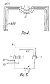
- Figure 4 illustrates a feature of all three structures not apparent from the views taken in Figures 1, 2 and 3; and
- Figure 5 illustrates a modification. In all figures, like references are used for like parts.
- Referring to Figure 1 the cathode emitting material 1 of the cathode is provided within a
spherical depression 2 within aU-shaped strip 3 of a high resistance alloy, in this case nickel tungsten. The U-shapedstrip 3 is located within and supported by two blocks of copper referenced 4 and 5 respectively. - Beneath, as viewed, the U-shaped
strip 2 is another U-shapedstrip 6 of a low resistance material, in this case molybdenum. Whilststrip 6 is spaced from the underside ofstrip 3 the two strips closely conform to one another in their configurations. In this example, both strips are of similar widths (i.e. of similar dimensions in a direction tranverse to the directions of current flow). - U-shaped
strip 6 is mounted in, and supported at one end, by the copper block 4 and at its other end by anindependent copper block 7. - The
surface 8 ofstrip 6 facing thestrip 3 is polished, on all three sides, so as to reflectbackto strip 3 any heat that radiates in the direction ofstrip 6 fromstrip 3. - In operation heater current is passed from
copper block 5 tocopper block 7 viastrips strip 3 forms a substrate for the cathode material of course, withstrip 6 forming the return path. Thus, currents flowing instrips - Referring to Figure 2 the cathode arrangement illustrated therein is essentially similar to that illustrated in Figure 1 (and like references are used for like parts) save for the shapes of the
copper blocks - Referring to Figure 3 in this case a cathode arrangement is shown in which the
strips depression 2 in member 3' and the surfaces of member 6' which face member 3' are polished. Whilst not shown, one side of generally cylindrical member 3' together with the corresponding side of generally cylindrical member 6' are mounted together in a block 4 which generally corresponds to the block 4 as illustrated in Figure 2 whilst the other sides of generally cylindrical members 3' and 6' are mounted respectively inblocks blocks - Referring to Figure 4, this illustrates in schematic fashion a feature of all three structures described with reference to Figures 1 to 3, i.e. that the second layers (
strip 6 in the case of Figures 1 and 3 and member 6' in the case of Figure 3) exhibit a cylindrical depression 2' which corresponds to thecylindrical depression 2 within which the cathode emitting material is provided. - Referring to Figure 5 this illustrates a modification which, although described as applied to the structure of Figure 1, may be applied to any of the arrangements described hereinbefore. Represented are the
strips copper blocks blocks - Connected electrically in shunt with
strip 3 is animpedance 11. In thiscase impedance 11 is outside of the tube envelope and adjustable so as adjustably to reduce the current flowing instrip 3 compared to the current flowing instrip 6. This takes into account the fact that the strength of a magnetic field decreases with increasing distance from the current carrying conductor which creates it and by providing for the field produced by the current inconductor 6 to be greater than that produced by the current inconductor 3, a degree of compensation is achieved for the distance necessarily separating the two conductors.Impedance 11 may be adjusted to optimise the neutralisation effect achieved.
Claims (12)
Priority Applications (1)
| Application Number | Priority Date | Filing Date | Title |
|---|---|---|---|
| AT84306572T ATE32397T1 (en) | 1983-10-07 | 1984-09-27 | TRAVELING FIELD TUBES. |
Applications Claiming Priority (2)
| Application Number | Priority Date | Filing Date | Title |
|---|---|---|---|
| GB8326854 | 1983-10-07 | ||
| GB08326854A GB2147732B (en) | 1983-10-07 | 1983-10-07 | Improvements in or relating to travelling wave tubes |
Publications (2)
| Publication Number | Publication Date |
|---|---|
| EP0138462A1 EP0138462A1 (en) | 1985-04-24 |
| EP0138462B1 true EP0138462B1 (en) | 1988-02-03 |
Family
ID=10549817
Family Applications (1)
| Application Number | Title | Priority Date | Filing Date |
|---|---|---|---|
| EP84306572A Expired EP0138462B1 (en) | 1983-10-07 | 1984-09-27 | Improvements in or relating to travelling wave tubes |
Country Status (6)
| Country | Link |
|---|---|
| US (1) | US4658181A (en) |
| EP (1) | EP0138462B1 (en) |
| AT (1) | ATE32397T1 (en) |
| CA (1) | CA1237467A (en) |
| DE (1) | DE3469242D1 (en) |
| GB (1) | GB2147732B (en) |
Families Citing this family (5)
| Publication number | Priority date | Publication date | Assignee | Title |
|---|---|---|---|---|
| US5329129A (en) * | 1991-03-13 | 1994-07-12 | Mitsubishi Denki Kabushiki Kaisha | Electron shower apparatus including filament current control |
| US5841219A (en) * | 1993-09-22 | 1998-11-24 | University Of Utah Research Foundation | Microminiature thermionic vacuum tube |
| KR100382062B1 (en) * | 1996-05-22 | 2003-09-19 | 삼성에스디아이 주식회사 | Direct Cathode Structure |
| US5955828A (en) * | 1996-10-16 | 1999-09-21 | University Of Utah Research Foundation | Thermionic optical emission device |
| DE112006002464T5 (en) * | 2005-09-14 | 2008-07-24 | Littelfuse, Inc., Des Plaines | Gas-filled surge arrester, activating connection, ignition strips and manufacturing process therefor |
Family Cites Families (15)
| Publication number | Priority date | Publication date | Assignee | Title |
|---|---|---|---|---|
| GB151710A (en) * | ||||
| GB335573A (en) * | 1929-06-24 | 1930-09-24 | Westinghouse Lamp Co | Improvements in thermionic cathodes of vacuum electric tube devices |
| FR707651A (en) * | 1929-12-17 | 1931-07-10 | Arcturus Radio Tube Co | Improvements to electronic tubes |
| BE467619A (en) * | 1939-09-08 | |||
| BE522260A (en) * | 1952-08-22 | |||
| GB833432A (en) * | 1955-06-25 | 1960-04-27 | Emi Ltd | Improvements in or relating to indirectly heated cathodes for electron discharge devices and to heater elements therefor |
| JPS464029Y1 (en) * | 1968-05-28 | 1971-02-12 | ||
| US3783330A (en) * | 1971-04-02 | 1974-01-01 | Mitsubishi Electric Corp | Direct heated cathode |
| JPS536560A (en) * | 1976-07-07 | 1978-01-21 | Hitachi Ltd | Manufacture of cathode for direct heating type cathode ray tube |
| JPS5596531A (en) * | 1979-01-19 | 1980-07-22 | Hitachi Ltd | Directly heated cathode for electron tube |
| JPS55144631A (en) * | 1979-04-28 | 1980-11-11 | Hitachi Ltd | Directly-heated cathode for electronic tube |
| US4388551A (en) * | 1980-11-24 | 1983-06-14 | Zenith Radio Corporation | Quick-heating cathode structure |
| US4459322A (en) * | 1981-12-28 | 1984-07-10 | North American Philips Consumer Electronics Corp. | Method for producing cathode structure for cathode ray tubes utilizing urea-containing slurry |
| US4471267A (en) * | 1982-06-14 | 1984-09-11 | Hughes Aircraft Company | Grid structure for certain plural mode electron guns |
| US4553064A (en) * | 1983-08-30 | 1985-11-12 | Hughes Aircraft Company | Dual-mode electron gun with improved shadow grid arrangement |
-
1983
- 1983-10-07 GB GB08326854A patent/GB2147732B/en not_active Expired
-
1984
- 1984-09-27 DE DE8484306572T patent/DE3469242D1/en not_active Expired
- 1984-09-27 EP EP84306572A patent/EP0138462B1/en not_active Expired
- 1984-09-27 AT AT84306572T patent/ATE32397T1/en active
- 1984-10-05 CA CA000464878A patent/CA1237467A/en not_active Expired
- 1984-10-09 US US06/658,790 patent/US4658181A/en not_active Expired - Fee Related
Also Published As
| Publication number | Publication date |
|---|---|
| US4658181A (en) | 1987-04-14 |
| DE3469242D1 (en) | 1988-03-10 |
| CA1237467A (en) | 1988-05-31 |
| ATE32397T1 (en) | 1988-02-15 |
| GB8326854D0 (en) | 1983-11-09 |
| GB2147732A (en) | 1985-05-15 |
| GB2147732B (en) | 1987-11-04 |
| EP0138462A1 (en) | 1985-04-24 |
Similar Documents
| Publication | Publication Date | Title |
|---|---|---|
| US6872882B2 (en) | Areal electric conductor comprising a constriction | |
| CA1219644A (en) | Shielded heating element having intrinsic temperature control | |
| WO2013077994A1 (en) | Apparatus and methods for improving reliability of rf grounding | |
| US6115453A (en) | Direct-Heated flats emitter for emitting an electron beam | |
| US4658181A (en) | Travelling wave tubes | |
| US5343021A (en) | Heater mounted on a substrate having a hole penetrating through the substrate | |
| GB2183904A (en) | Cathode focusing arrangement | |
| US5015908A (en) | Fast warm-up cathode for high power vacuum tubes | |
| US2364732A (en) | Ultra high frequency generator | |
| US2075855A (en) | Magnetron | |
| US4176293A (en) | Thermionic cathode heater having reduced magnetic field | |
| US3450927A (en) | Thermionic cathode with heat shield having a heating current by-pass | |
| GB2296371A (en) | Cathode arrangements utilizing diamond as an insulator | |
| US4631744A (en) | X-ray tube | |
| US3549852A (en) | Integral microwave radiating and generating unit for heating | |
| US3090883A (en) | Electric high pressure discharge lamps | |
| US5007074A (en) | X-ray tube anode focusing by low voltage bias | |
| US2717947A (en) | Non-inductive electrical resistor and means for mounting the same | |
| CN112798650A (en) | A device and method for testing cathode electron bombardment resistance | |
| EP0326273A2 (en) | Directly heated cathodes | |
| KR19990039198A (en) | Blocking Capacitor of Microwave Oscillating Tube for Microwave Oven | |
| GB2138629A (en) | High-frequency gas-discharge lamp system | |
| JPH0567442A (en) | X-ray tube | |
| JPH11339701A (en) | Electron beam tube | |
| Mortazavi et al. | A design upgrade of the RF cavity and its power window for high current operation of the NSLS X-ray storage ring |
Legal Events
| Date | Code | Title | Description |
|---|---|---|---|
| PUAI | Public reference made under article 153(3) epc to a published international application that has entered the european phase |
Free format text: ORIGINAL CODE: 0009012 |
|
| AK | Designated contracting states |
Designated state(s): AT BE CH DE FR IT LI LU NL SE |
|
| 17P | Request for examination filed |
Effective date: 19851017 |
|
| 17Q | First examination report despatched |
Effective date: 19860513 |
|
| GRAA | (expected) grant |
Free format text: ORIGINAL CODE: 0009210 |
|
| AK | Designated contracting states |
Kind code of ref document: B1 Designated state(s): AT BE CH DE FR IT LI LU NL SE |
|
| PG25 | Lapsed in a contracting state [announced via postgrant information from national office to epo] |
Ref country code: NL Effective date: 19880203 Ref country code: LI Effective date: 19880203 Ref country code: CH Effective date: 19880203 Ref country code: BE Effective date: 19880203 Ref country code: AT Effective date: 19880203 |
|
| REF | Corresponds to: |
Ref document number: 32397 Country of ref document: AT Date of ref document: 19880215 Kind code of ref document: T |
|
| ITF | It: translation for a ep patent filed | ||
| PG25 | Lapsed in a contracting state [announced via postgrant information from national office to epo] |
Ref country code: SE Effective date: 19880229 |
|
| REF | Corresponds to: |
Ref document number: 3469242 Country of ref document: DE Date of ref document: 19880310 |
|
| ET | Fr: translation filed | ||
| REG | Reference to a national code |
Ref country code: CH Ref legal event code: PL |
|
| NLV1 | Nl: lapsed or annulled due to failure to fulfill the requirements of art. 29p and 29m of the patents act | ||
| PG25 | Lapsed in a contracting state [announced via postgrant information from national office to epo] |
Ref country code: LU Free format text: LAPSE BECAUSE OF NON-PAYMENT OF DUE FEES Effective date: 19880930 |
|
| PLBE | No opposition filed within time limit |
Free format text: ORIGINAL CODE: 0009261 |
|
| STAA | Information on the status of an ep patent application or granted ep patent |
Free format text: STATUS: NO OPPOSITION FILED WITHIN TIME LIMIT |
|
| 26N | No opposition filed | ||
| PGFP | Annual fee paid to national office [announced via postgrant information from national office to epo] |
Ref country code: FR Payment date: 19890908 Year of fee payment: 6 |
|
| ITTA | It: last paid annual fee | ||
| PGFP | Annual fee paid to national office [announced via postgrant information from national office to epo] |
Ref country code: DE Payment date: 19891110 Year of fee payment: 6 |
|
| PG25 | Lapsed in a contracting state [announced via postgrant information from national office to epo] |
Ref country code: FR Effective date: 19910530 |
|
| PG25 | Lapsed in a contracting state [announced via postgrant information from national office to epo] |
Ref country code: DE Effective date: 19910601 |
|
| REG | Reference to a national code |
Ref country code: FR Ref legal event code: ST |