EP0138408A2 - An electromagnet and a method for manufacturing it - Google Patents
An electromagnet and a method for manufacturing it Download PDFInfo
- Publication number
- EP0138408A2 EP0138408A2 EP84306400A EP84306400A EP0138408A2 EP 0138408 A2 EP0138408 A2 EP 0138408A2 EP 84306400 A EP84306400 A EP 84306400A EP 84306400 A EP84306400 A EP 84306400A EP 0138408 A2 EP0138408 A2 EP 0138408A2
- Authority
- EP
- European Patent Office
- Prior art keywords
- yoke
- coil member
- core
- pieces
- coil
- Prior art date
- Legal status (The legal status is an assumption and is not a legal conclusion. Google has not performed a legal analysis and makes no representation as to the accuracy of the status listed.)
- Granted
Links
- 238000000034 method Methods 0.000 title claims description 22
- 238000004519 manufacturing process Methods 0.000 title claims description 9
- 239000000945 filler Substances 0.000 claims abstract description 26
- 230000004907 flux Effects 0.000 claims abstract description 17
- 239000000463 material Substances 0.000 claims description 36
- 230000002093 peripheral effect Effects 0.000 claims description 25
- 239000007788 liquid Substances 0.000 claims description 6
- 239000000696 magnetic material Substances 0.000 claims description 5
- 230000000694 effects Effects 0.000 claims description 4
- 239000011230 binding agent Substances 0.000 claims 2
- 238000007493 shaping process Methods 0.000 claims 2
- 230000015572 biosynthetic process Effects 0.000 claims 1
- 238000005755 formation reaction Methods 0.000 claims 1
- 238000010276 construction Methods 0.000 abstract description 12
- 239000002184 metal Substances 0.000 abstract description 2
- 229910052751 metal Inorganic materials 0.000 abstract description 2
- 230000009467 reduction Effects 0.000 abstract description 2
- 239000006185 dispersion Substances 0.000 abstract 1
- 239000003921 oil Substances 0.000 description 10
- 238000003466 welding Methods 0.000 description 8
- 229910000976 Electrical steel Inorganic materials 0.000 description 6
- 238000005192 partition Methods 0.000 description 6
- 229910000831 Steel Inorganic materials 0.000 description 5
- 230000000903 blocking effect Effects 0.000 description 5
- 238000005498 polishing Methods 0.000 description 5
- 239000010959 steel Substances 0.000 description 5
- 238000004891 communication Methods 0.000 description 4
- 238000006073 displacement reaction Methods 0.000 description 4
- 238000002347 injection Methods 0.000 description 4
- 239000007924 injection Substances 0.000 description 4
- 238000000465 moulding Methods 0.000 description 4
- 230000008569 process Effects 0.000 description 4
- 229920003002 synthetic resin Polymers 0.000 description 4
- 239000000057 synthetic resin Substances 0.000 description 4
- 230000004323 axial length Effects 0.000 description 3
- 230000003247 decreasing effect Effects 0.000 description 3
- 150000003376 silicon Chemical class 0.000 description 3
- RYGMFSIKBFXOCR-UHFFFAOYSA-N Copper Chemical compound [Cu] RYGMFSIKBFXOCR-UHFFFAOYSA-N 0.000 description 2
- XEEYBQQBJWHFJM-UHFFFAOYSA-N Iron Chemical compound [Fe] XEEYBQQBJWHFJM-UHFFFAOYSA-N 0.000 description 2
- 239000007767 bonding agent Substances 0.000 description 2
- 238000006243 chemical reaction Methods 0.000 description 2
- 238000005520 cutting process Methods 0.000 description 2
- WABPQHHGFIMREM-UHFFFAOYSA-N lead(0) Chemical compound [Pb] WABPQHHGFIMREM-UHFFFAOYSA-N 0.000 description 2
- 230000007935 neutral effect Effects 0.000 description 2
- 238000007711 solidification Methods 0.000 description 2
- 230000008023 solidification Effects 0.000 description 2
- 239000000853 adhesive Substances 0.000 description 1
- 230000001070 adhesive effect Effects 0.000 description 1
- 239000004020 conductor Substances 0.000 description 1
- 229910052802 copper Inorganic materials 0.000 description 1
- 239000010949 copper Substances 0.000 description 1
- 238000004512 die casting Methods 0.000 description 1
- 238000010292 electrical insulation Methods 0.000 description 1
- 239000012777 electrically insulating material Substances 0.000 description 1
- 229910052742 iron Inorganic materials 0.000 description 1
- 238000003754 machining Methods 0.000 description 1
- 230000007246 mechanism Effects 0.000 description 1
- 238000003825 pressing Methods 0.000 description 1
- 230000001846 repelling effect Effects 0.000 description 1
- 229920005989 resin Polymers 0.000 description 1
- 239000011347 resin Substances 0.000 description 1
- 102200082907 rs33918131 Human genes 0.000 description 1
- 102200082816 rs34868397 Human genes 0.000 description 1
- 239000007787 solid Substances 0.000 description 1
- 238000004381 surface treatment Methods 0.000 description 1
Images


Classifications
-
- H—ELECTRICITY
- H01—ELECTRIC ELEMENTS
- H01F—MAGNETS; INDUCTANCES; TRANSFORMERS; SELECTION OF MATERIALS FOR THEIR MAGNETIC PROPERTIES
- H01F41/00—Apparatus or processes specially adapted for manufacturing or assembling magnets, inductances or transformers; Apparatus or processes specially adapted for manufacturing materials characterised by their magnetic properties
- H01F41/005—Impregnating or encapsulating
-
- H—ELECTRICITY
- H01—ELECTRIC ELEMENTS
- H01F—MAGNETS; INDUCTANCES; TRANSFORMERS; SELECTION OF MATERIALS FOR THEIR MAGNETIC PROPERTIES
- H01F7/00—Magnets
- H01F7/06—Electromagnets; Actuators including electromagnets
- H01F7/08—Electromagnets; Actuators including electromagnets with armatures
- H01F7/081—Magnetic constructions
-
- H—ELECTRICITY
- H01—ELECTRIC ELEMENTS
- H01F—MAGNETS; INDUCTANCES; TRANSFORMERS; SELECTION OF MATERIALS FOR THEIR MAGNETIC PROPERTIES
- H01F7/00—Magnets
- H01F7/06—Electromagnets; Actuators including electromagnets
- H01F7/08—Electromagnets; Actuators including electromagnets with armatures
- H01F7/16—Rectilinearly-movable armatures
- H01F2007/1676—Means for avoiding or reducing eddy currents in the magnetic circuit, e.g. radial slots
Definitions
- This invention relates to an electromagent to operate a magnet valve apparatus and other mechanisms and more particularly to an electromagnet in which a circular cylindrical coil, a stator core and an armature core mounted about the axis of the coil and a yoke to lead the magnetic flux generated by feeding the coil with an alternate current to the stator core and the armature core are included and the armature core is pulled by the stator core under the electromagnetic force due to the magnetic flux.
- the yoke is made of laminated silicon steel sheets for the purpose of preventing the generation of eddy current.
- the yoke is usually made in the form of a rectangular cylinder consisting of such a number of laminated silicon'steel strips as is sufficient to obtain a cross-sectional area to pass satisfactorily the magnetic flux generated by the coil.
- an air gap of a considerable thickness must be left between the circular cylindrical coil and the yoke, there is an undesirable and general tendency that the outermost-dimension of the yoke is increased by an amount corresponding to the air gap and the electromagnet becomes relatively large-sized for the available electromagnetic performance as an electromagnet.
- an object of the present invention is to provide an electromagnet in which eddy current is generated only to a very reduced degree due to a devised construction of many laminated yoke pieces.
- Another object of the present invention is to provide an electromagnet construction which can be made small-sized despite the adopted laminated construction.
- each one of the many yoke pieces can be brought close to or even in contact with the outer side surface of the coil.
- the outermost size as an electromagnet can be limited to the minimum value.
- Still another object of the present invention is to provide an electromagnet in which the leakage magnetic flux of the coil is reduced and a relatively large electromagnetic force for the electric power put into the coil can be exerted on the armature core.
- Still another object of the present invention is to provide a method of manufacturing an electromagnet of the above described construction with ease.
- a magnet valve apparatus comprises a valve device 1, an electromagnet 2 for actuating the valve device 1 and a terminal box 3 to which the ends of the power supply wires for the electromagnet is connected.
- a body 4 is provided interiorly with a space 5 for advance and retreat of a spool 11 and with an oil passage 6.
- the body is also provided with a port 7 for communication with a hydraulic pressure supply (for example, a pump), ports 8 for communication with a pressure-oil tank, and ports 9 and 10 for communication with a driven device, for example, a hydralulic cylinder and these ports are in communication as well with the aforesaid space 5 for advance and retreat of the spool 11 or with the oil passage 6.
- a hydraulic pressure supply for example, a pump
- ports 8 for communication with a pressure-oil tank
- ports 9 and 10 for communication with a driven device, for example, a hydralulic cylinder and these ports are in communication as well with the aforesaid space 5 for advance and retreat of the spool 11 or with the oil passage 6.
- the well known spool 11 is mounted for right and left travel as viewed in Fig. 1.
- a spring seat 12 is capped and a spool restoring spring 13 is compressively inserted between the spring seat 12 and each of threaded connectors of an electromagnet to be
- This electromagnet consists of an actuator 16 to operate mechanically the aforementioned valve device 1 and of a magnetizer 17 adapted to impart magnetic flux to the actuator 16.
- the actuator 16 has a stator core 20 which, at one end thereof, has an integral threaded connector 21 adapted threadedly in the body 4 of the valve device 1.
- the stator core 20 has also a flange portion 22 by which a ceiling 0-ring 23 is pressed down.
- the stator core 20 has further a through hole 24 where a push rod 25 is inserted for the right and left displacement as viewed in Fig. 1.
- a tube member 26 is capped on the other end portion of the stator core 20 and both the ends portions are hermetically welded to seal off the space inside the tube.
- the tube member 26 is made of a nonmagnetic material, defining a space for advance and retreat of the armature core 31.
- To the other end portion of the tube member 26 is hermetically welded a blocking member 27.
- the blocking member 27 is provided with a through hole 28 in which a push pin 29 for manual actuation is inserted for movement to the left of Fig. 1 and return to the shown position.
- the hermetic seal between the through hole 28 and the push pin 29 is maintained by an 0-ring 30.
- an armature core 31 is disposed for the right and left travel in Fig. 1.
- an oil passage groove 32 is cut over the full axial length of the armature core 31 so that oil may flow through the groove 32 between the left and the right ends of the armature core 31 as seen in Fig. 1.
- the actuator 16 goes by the name of a tube assembly.
- an account is given of the magnetizer 17.
- This magnetizer 17 is situated outside the actuator 16 and is prevented by a stop fitting 18 from departing the valve device 1.
- the magnetizer 17 is provided with a housing 35, which is made of synthetic resins in one case and is prepared as a die casting in another.
- the coil assembly 36 which comprises a cylindrical coil member 38 and a yoke 44 formed so as to enclose the former.
- the coil member 38 consists of a cylindrical coil bobbin 39 with a flange at either end thereof and a coil wire 40 covoluted on the bobbin 39. From one of the flanges of the bobbin 39 is extending a tongue piece 41 whose tip is provided with a plug holder 42.
- a lead wire 40a of the aforesaid coil wire 40 is connected to a plug 43 held by the plug holder 42.
- the coil bobbin 39 is made of a material of sufficient electrical insulation and the coil wire is a wire of little electrical resistance, for example, a copper wire.
- the yoke 44 consists of plural (two in the present embodiment) yoke elements 45.
- Each yoke element 4 '5 comprises an auxiliary outer frame 46 and a plurality of similar yoke pieces 47 arranged radially towards the axis of the coil member 38.
- the outer frame 46 is preferably made of a magnetic material for the outer frame to be utilized as a part of a magnetic circuit but need not be so.
- the yoke pieces 47 are necessarily made of a magnetic material.
- Each yoke piece 47 formed of an intermediate member 48 to be positioned at the cylindrical surface of the coil member 38 and end members 49 extending integrally from both ends of the intermediate member 48 as shown in Fig. 6.
- the intermediate member 48 is substantially of the same length as the coil member 38 (slightly longer by a clearance for assembling to be described later).
- the width of the intermediate member of every yoke piece is selected to be sufficient to pass satisfactorily the magnetic flux generated by the coil member 38.
- the end member 49 has a length equal to the sum of the thickness of the coil member 38 and the width of the intermediate member 48.
- the width of the end member (the length thereof along the axis of the coil member 38) is selected to be sufficient to pass the magnetic flux of the coil member 38.
- the intermediate members 48 of all the yoke pieces 47 form a substantially cylindrical yoke portion enclosing the coil member 38.
- the cylindrical yoke portion has longitudinal cuts but the cuts of such width as that of the present embodiment interfere in no way with the function to conduct magnetic flux.
- the end members 49 of many yoke pieces 47 all together form two flange-shaped yoke portions, one connecting magnetically the cylindrical surface of the space for advance and retreat of the armature core 31 to one end of the aforementioned cylindrical yoke portion, and the other connecting similarly the cylindrical surface of the stator core to the other end of the cylindrical yoke portion.
- This terminal box comprises a main box 52 and a lid 53 put on it, and both are made of an electrically insulating material such as synthetic resins.
- the main box 52 consists of a base member 54 and partition wall members 55 and 56, and the base member 54 together with the partition wall member 55 is fixed on the body 4 of the valve device 1 with fastening screws 57. Between the base member 54 and the partition wall member 55 is prepared a disposition space 58 where a control circuit 59 is disposed.
- This circuit 59 includes a plurality of circuit components 61, a socket 62, pilot lump 63 and so on all mounted on a printed-circuit board 60.
- To the socket 62 the plug 45 is connected detachably as shown clearly in Fig. 1.
- the partition wall member 56 is provided with terminals 64 and as well with an integral wire inlet 65 through which power supply wires are taken in to be connected to the terminals 64.
- the lid 53 is secured on the main box 52 with mounting screws 66.
- the other electromagnet similar to the aforementioned electromagnet 2 is mounted at the left side of the vlave device 1 as seen in Fig. 1 (only a part of the stator core of the other electromagnet being shown), and a plug of the other electromagnet is connected to a socket 62 provided to the left hand side of the control circuit 59.
- the electric power is supplied to the terminals 64 through the wires taken in from outside in the magnet valve apparatus of the aforementioned construction, the electric power is sent to the coil wire 40 through the control circuit 59 and further through the plug 43.
- the pilot lamp 63 is lighted in a well known manner.
- the eddy current loss in the yoke 44 can be decreased and the energy of the electric current can be used effectively for the operation of the armature core 31 even if the current is alternating. Namely, when a certain amount of magnetic flux passes through the yoke as the result of the power feed to the coil wire 40, it is difficult for an eddy current of considerable strength to flow in the yoke 44, which consists of many yoke pieces 47 arranged radially, and the eddy current loss in the yoke is small. Thus, electric energy can be used effectively as described above.
- the heat generated by the coil wire 40 when a current is turned on in the coil wire 40 to operate the electromagnet, the heat generated by the coil wire 40, if any, can be given off effectively to outer regions of the apparatus. That is, in the yoke 44 enclosing the peripheral surface of the coil member 38, a number of yoke pieces 47 are radially arranged. Consequently, the heat generated by the coil wire 40 is first transmitted from the outer peripheral surface of the coil member 38 to the inner peripheral edges of the yoke pieces 47 and is directly conducted outwards along the radially disposed yoke pieces 47 to be conveyed to the outer peripheral edges of the yoke pieces 47. Accordingly, the heat generated by the coil can be released from whole the broad outer peripheral surface of the yoke 44.
- each yoke piece 47 can be brought further to and released at the outer peripheral surface of the housing 35 by more direct heat conduction due to the outerframe 46, the filler member 37 and the housing'35.
- the housing 35 and the coil assembly are manufactured separately.
- the coil assembly 36 is manufactured in the following manner. Namely, the coil wire 40 is fist covolted on the coil bobbin 39 and the lead wire 40a for the coil wire 40 is connected to the plug 43, the coil member 38 as shown in Fig. 4 being formed.
- the plural yoke elements 45 are made in a separate process other than that for the coil member 38.
- a necessary number of outer frames 46 as shown in Fig. 5 are prepared and at the same time a number of yoke pieces 47 as shown in Fig. 6 are also prepared.
- an assembling jig which consists of an enclosing member 71 as shown in Figs. 8 and 9 and of a center column 72 adapted in it dismountably along its axis.
- the diameter of the center column 72 is made equal to that of the aforementioned actuator 16.
- the outer frame 46 and a plurality of yoke pieces 47 having been adapted therein are taken out so that the yoke pieces may not be in bits.
- the yoke elements 45 having been taken out, are put on the coil 38 prepared beforehand in the form as shown in Fig. 4 and the form as shown in Fig. 3 is constructed.
- the aforementioned coil assembly 36 is inserted into the housing 35.
- a positioning jig 74 is set in the coil assembly 36.
- This positioning jig 74 consists of a setting portion adaptable to the outer periphery of the opening side of the housing 35 and of a rod member 76 adapted to be inserted in the coil assembly 36 and positions the coil assembly 36 against the housing 35.
- the rod member 76 is formed to be as thick as the aforementioned actuator 16.
- a suitable type of liquid filler material is poured into the housing 35 through an injection port 77 formed in the jig 74. This filler material is made to stream in among the coil member 38, respective yoke pieces 47 and the outer frame 46 in the coil assembly 36 as well as between.the housing 35 and the coil assembly 36. Having been poured, the filler material is solidified.
- the liquid filler material is prevented from streaming out, since the housing 35 is shut up a forehand with a bottom plate 35a .as shown in Fig. 11.
- the jig 74 as well as the bottom plate 35a is removed. By the step to this point the magnetizer 17 is completed.
- the rod member 76 in the positioning jig 74 is made of a magnetizable material and an electric current is turned on in the coil member 38 of the coil assembly 36 through plugs 43, the following effects can be obtained. That is, as the result of the aforementioned energization of the coil member 38, the rod member 76 is magnetized to become an electromagnet. Consequently, the internal peripheral edges 49a of the end members 49 in many yoke pieces 47 are pulled by the rod member 76 as shown in Fig. 12. In this manner, the internal peripheral edges 49a of the end members 49 in many yoke pieces 47 are in alignment in good order around the outer peripheral surface of the rod member 76.
- the external peripheral edges 49b of the end members 49 are repelling one another to be arranged side by side at regular intervals as shown in Fig. 12, since all of the external peripheral edges 49b are magnetized to be of the same polarity (for example, N pole). Therefore, if the filler material is poured among the yoke pieces 47 in such an alignment and is solidified there, many yoke pieces 47 can be fixed in good order at substantially regular intervals. Furthermore, since the internal peripheral edges 49a in the coil assembly 36 formed in the aforementioned manner are arranged in good order as described above, the internal peripheral edges 49a in the assembled electromagnet 2 come to positions very close to the stator core 20 or the armature core 31 of the actuator 16.
- the reluctance of the aforementioned magnetic circuit is decreased and a powerful actuating force can be generated in the armature core 31. Furthermore, the heat generated by the coil member 38 on energization thereof can be utilized to quicken the solidification of the filler material.
- the actuator 16 is manufactured separately from the magnetizer 17. Namely, the tube member 26 is put on the stator core 20, both are fixed to each other by welding and the armature core 31 is insertedly mounted in the tube member 26. Further, the push pin 29 is inserted in the through hole 28 of the blocking member 27, which is then fixed to the tube member 26 by welding. The actuator 16 is thus completed. Next, an account is given of the assembling process of the magnet valve apparatus. First, the actuator 16 is connected to the valve body 4 by screwing the threaded connector 21 into the threaded hole of the valve body 4. Then, the magnetizer 17 is put on the outer peripheral surface of the actuator 16.
- the magnetizer 17 is fixed relative to the valve device 1, and the magnet valve apparatus is completed.
- FIGs. 13 and 14 show a different example of the assembling jig for the yoke elements 46 (unlike that shown in Figs. 8 and 9).
- an enclosing member 71e is formed integral with a center column 72e. If a member in these figures is considered to be the same as or alike to the corresponding one in previous figures, it is given a numeral same as in the previous figures but with an alphabet e and repeated description has been omitted. (In any of the following figures, an alphabet f, g, ----- or so on is successively affixed to a numeral according to the same idea and the repeated description is again omitted.)
- Fig. 15 shows a different example of the method for injecting the filler material.
- a mould consists of two members 78 and 79 and the latter is provided with a rod member 76f.
- a housing 35f containing a coil assembly therein is adapted between the elements 79 and 78.
- the filler material is poured between the housing 35f and the coil assembly 36f through an injection port 77f and the filler material is solidified.
- the elements 78 and 79 are separated from each other.
- a magnetizer 17f is completed.
- Fig. 16 shows a still different example of the moulding method of a magnetizer 17g.
- the moulding according to this Fig. 16 is performed with the mould as shown in Fig. 15.
- the moulding is done without using the housing. Namely, a coil member 38g and a yoke 44g are positioned around a center column 76g of an element 79g and, with these kept there, elements 78g and 79g are combined.
- the filler material is injected through an injection port 77g to be solidified.
- the injected filler material on solidification thereof, becomes a member which functions as a housing. It is preferable as well in this example to energize the coil member 38g through plugs 43g as in the previous case.
- Figs. 17 and 18 show a different example of the jig used for the assembling of yoke elements 45h.
- This jig consists of an outer frame 81, an inner frame 82 divisible into two sections and a core 83.
- the assembling of the yoke element 45h with use of such a jig is performed as follows. First, a number of yoke pieces 47h are arranged and fixed around the core as shown in Fig. 17, and the pieces 47h together with the core 83 are inserted into the inner frame 82 which has been set in the outer frame 81. Then, a bonding agent, for example liquid resins or adhesives, is poured through an injection port 84 formed between the inner frame 82 and the core 83.
- a bonding agent for example liquid resins or adhesives
- the outer frame 81 is first taken off, then the inner frame 82 is divided into two sections and lastly the finished yoke element 45h is detached from the core 83. Since all the many yoke pieces 47h in the yoke element 45h finished in this manner are unified rigidly, the works in the next step, i.e. setting the yoke element around the coil member and inserting them into the housing, can be carried out easily. If the core 83 of the present example is made of a permanent magnet, the work to arrange and fix the many yoke pieces around the core 83 and to insert them into the inner frame 82 is made easy.
- the many yoke pieces 47h can be joined (to keep) the plural yoke pieces 47h around the core 83 under the magnetic force thereof and the many yoke pieces can be prevented from dispersing. Moreover, with use of such a magnetized core, the many yoke pieces can be arranged in good order as in the case described in reference to Fig. 12.
- FIG. 19 shows a still different example of the assembling jig. This example of the assembling jig differs from that shown in Figs. 17 and 18 in the partition position of an inner frame 82i.
- Fig. 20 shows a different embodiment of the present invention.
- a yoke 44j is designed to consists of four yoke elements 45j.
- the number of the yoke elements is not limited to 2 of the previous embodiment or 4 of the present embodiment but may be 3 or an arbitrary number more than 3.
- a different example of the form of the yoke pieces is shown in Figs. 21 and 22.
- a yoke piece 47k shown in these figures is so formed that its thickness is decreasing towards the internal peripheral edge, i.e. increasing towards the external peripheral edge.
- a finished yoke element 44k as shown in Fig. 28 a plurality of the yoke elements 47k made in this form can be arranged closely without any air gaps. Consequently, a magnetic circuit of a large cross section can be provided and hence the reluctance of it is lowered.
- the radial dimension of the magnetic circuit can be reduced to obtain a magnetic circuit cross section of a certain area and hence it is possible to promote the miniaturization of an electromagnet.
- a yoke piece 47l is formed with space securing projections 86.
- This projection can be made by protruding a small part of a yoke piece 47t simultaneously when it is died from a metal sheet material (magnetic sheet material).
- the yoke pieces, each having such a projection 86, can be arranged systematically at regular intervals.
- an engage projection 87 is formed on the top of a space securing projection 86m, whereas the rear side of the space securing projection 86m is shaped to present an engage recess 88.
- a yoke element 46m is assembled from these yoke pieces 47m, they can be unified just by arranging them in such a manner that the engage projection 87 of one of the yoke pieces 47m may engage with the engage recess 88 of another of the yoke pieces 47m. Accordingly, the yoke element 46m can be assembled without using the aforementioned outer frame as shown in Fig. 29.
- an actuator 98 includes a hollow container 92, which consists of a connector 93 for connection to the body of the v ⁇ l ve apparatus and of a receiver 94 for receipt of an armature core to be described later.
- the connector 93 is generally made of a magnetic material such as iron but may be made of a nonmagnetic metalic material.
- the receiver 94 consists of a cylindrical member 97 adapted to guide the advancing or retreating armature core and of an end member 98 integral with the cylindrical member 97. These members 97 and 98 are made of magnetic materials but may be made of nonmagnetic materials.
- an intermediate cylinder 99 is fixed to one end of the cylindrical member 97 by welding all over the peripheries of both ends.
- This intermediate cylinder 99 is situated inside the coil member and that outside the space for the advance and retreat of the armature core.
- this intermediate cylinder 99 is made of a nonmagnetic material in order to prevent that magnetic flux from passing through the structure of the intermediate cylinder 99 which should pass through the armature core and stator core.
- the other end of the cylinder 99 is fixed to a cylindrical portion 96 by welding all over their peripheries.
- the hollow container 92 is hermetically sealed.
- a stator 101 is fixedly provided close to the connector 93 and an armature core 102 is arranged for advance and retreat to the left and the right in Fig. 30.
- the stator core 101 consists of a central connection member 103 and a core main portion 104 disposed therearound.
- the connection member 103 consists of two elements 105 and 106 joined together.
- the connection member 103 is made of a high strength material such as S10C or S45C.
- Each of the elements 105 and 106 has, at its periphery, an annular joint portion 107, the cross section of which has a form suitable to constitute a dovetail groove.
- the element 105 is provided, in its central portion, with a through hole 108 in which the aforementioned push rod 25 is inserted.
- the core main portion 104 is constructed by assembling a plurality of such core elements 109 and 110 respectively as shown in Figs. 37 and 38. These many core elements 109 and 110 are arranged alternately as clearly shown in Fig. 32 and each of them is radially disposed around the central connection member 103.
- the core element 109 is made, for example, of a silicon steel sheet and the core element 110 of a magnetic steel sheet so that it may be difficult for eddy current to flow in the core main portion 104.
- the core piece 110 is made thicker towards the outer peripheral side, i.e. thinner towards the inner peripheral side. Consequently, when the core pieces 109 and 110 are laminated one upon another, they can be arranged in the form of an annulus around the connection member 103.
- Both the core pieces 109 and 110 may be made either of silicon steel sheets or magnetic steel sheets on which a surface treatment of arbitrary type is preferably applied to increase the superficial electric resistivity.
- the core pieces of both the above types are made of a single kind of material as in the above case, they need not be different in shapes from each other as shown in Figs. 37 and 38 but those core pieces of one type are suffice which have such a thickness as is suitable for the radially close arrangement of a plurality of them.
- the inner peripheral portion of each of the core pieces 109 and 110 is so formed as to present a joint member 111 having a shape conformable to the joint member 107 of the connection member 103.
- the above inner peripheral portion of the core pieces 109 and 110 is provided also with a recess 112.
- a number of the recesses 112 of all the core pieces 109 and 110 are disposed in succession to define an annular groove 113 as shown in Fig. 31.
- the core pieces 109 and 110 are further provided with a gain 114 for putting a shading coil therein.
- These gains 114 as well define an annular groove 115 as shown in Fig. 32.
- a shading coil 116 which is made of a good electrically conducting material such as copper and formed by an arbitrary method such as machining or out. or stanping
- armature core 102 is described referring to Figs. 40 to 42.
- This armature core 102 is constructed equivalently to the aforementioned stator core 101. That is, a connection member 117 consists of two elements 118 and 119 each of which has a joint portion 120.
- a core main portion 121 around the connection member 117 is formed of a plurality of those core pieces 122, each being made of a silicon steel sheet and those core pieces, each being made of a magnetic steel sheet, which are assembled radially about the axis of the connection member 117.
- each of the core pieces 122 and 123 has a joint portion 124, which is coupled with the joint portion 120 of the connection member 117.
- the core main portion 121 of the armature core 102 is provided, on its side surface, with an oil passage slot 125 which is cut lengthwise in the longitudinal direction of the armature core, i.e. in the direction of advance or retreat of the armature core.
- the slot 125 is formed by sandwiching several core pieces 122 1 and 123' of smaller radial size between the core pieces 122 and 123.
- An oil passage slot 126 is formed on that end surface of the core main portion 121 which is opposite to the stator core 101. This slot 126 is prepared by reducing the axial length of the core piece 122 1 , i.e. by reducing locally the axial length of the armature core 102 at the slot 126 as clearly shwon in Fig. 42.
- an oil passage slot 127 which communicates with the aforementioned oil passage slot 126.
- the distance L between the inner ends of a pair of opposting slots 127 is made smaller than the diameter of the push rod 25. Accordingly, even when the armature core 102 has been pulled by the stator core 101, a part of the slot 127 can communicate with the through hole 108 where the working oil flows.
- connection member 103 or 117 is used in the central region of the respective core 101 or 102 and so its cross-sectional area is much smaller compared with that of the core 101 or 102.
- the radius of the connection member is 1/3 of that of the core, the cross-sectional area of the connection member is reduced to 1/9, and if the radius 1/5, the cross-sectional area 1/25. If the cross-sectional area of the connection member is so much smaller, the generated eddy current is proportionately smaller. For this reason, the eddy current loss in the cores 101 and 102 is small.
- the push rod 25 advances and retreats repeatedly in the through hole 108 bored through the central portion of the stator core 101.
- any of the core pieces 109 and 110 does not touch the advancing or retreating push rod 25, since the through hole 108 is formed in the connection member 103.
- the operation of the apparatus over a long period does not result in relative displacements among the many core pieces 109 and 110.
- stator core 101 of the actuator 90 is manufactured as follows.
- One element 105 of the connection member as shown in Fig. 36, one element 106 of the connection member as shown in Fig. 36 and a number of core pieces 109 as shown in Fig. 37 and core pieces 110 as shown in Fig. 38 are prepared.
- the element 105 is fixed on the jig 128, prepared in advance, by an arbitrary method as shown in Fig. 9(A). For example, it is fixed by inserting a positioning rod 129 of the jig 128 into the through hole 108.
- the element 106 is securely fixed to the element 105 by caulking a part indicated by the numeral 130 and the reliable unification between the elements 105 and 106 and between these elements and core pieces 109 and 110 is obtained by welding a part indicated by the numeral 131.
- the outer surface of the core main portion 104 is processed by polishing (for example by centerless polishing) to be finished to a diameter suitable for tightly fitting in the cylindrical portion 96 of the hollow container 92 and inside the intermediate cylinder 99.
- both the end surfaces of the stator core 101 (the left and the right end surfaces in Fig. 33) are respectively finished to smooth planes by cutting.
- the shading coil 116 is fitted in the groove 115.
- This fitting procedure consists of inserting the coil 116 into the groove 115 and deforming a part indicated by a numeral 132 of Fig. 32 to the form as shown in Fig. 34 to make the coil 116 abut the side surface of the groove 115 and be fixed therein. In this manner, the stator core 101 is completed.
- the assembling of the armature core is performed similarly as in the case of the aforementioned stator core 101. That is, after the core main portion 121 has been combined with the connection member 117, the elements 118 and 119 are fixed to each other by caulking a part indicated by a numeral 133 and then the reliable unification between the elements 118 and 119 and between them and the pieces 122, 123, 122' and 123' is obtained by welding such parts, as indicated by numerals 134 and 135, respectively.
- the outer surface of core main portion 121 is processed by polishing and the armature core 102 is completed.
- connection member 93 and the receiver 94 of the hollow container 92 are formed independently of the above manufacturing work.
- the cylindrical member 97 and the intermediate cylinder 99 are welded together in advance and their internal surfaces are porcessed by polishing so that they may not interfere with the advance and retreat movement of.the armature core 102.
- the stator core 101, the armature core 102, push pins and so on are filled together in the hollow container 62 and thereby the actuator 90 is completed.
- the first step of this procedure is to fit the stator core 101 into the cylindrical member 96 of the connector 93. Meanwhile the push pins are inserted into the through holes of the receiver 94 and besides the armature core 102 is contained inside the receiver 94. Then, one end portion of the intermediate cylinder 99 of the receiver 94 is made to cover the stator core 101. Next, one end edges of the cylindrical portion 96 and the intermediate cylinder 99 of the receiver 94 are met to each other and welded together all over the periphery.
- the groove 113 of the stator core 101 is situated just inside the contacting edges of the cylindrical portion 96 and the intermediate cylinder 99. Accordingly, when the contacting edges are welded and hence heated, the heat due to welding scarecely diverges from there (the contacting edges are hard to be cooled) and as result of that, the contacting ends can be welded with ease and in addition with good work efficiency. In consequence of the above welding work, a raised stripe 136 is formed which rises from the contacting edges towards the bottom of the groove 113 as shown in Fig. 33.
- This raised stripe 136 is formed all over the circumference of the groove 113 and thereby that situation is realized where the displacement of the stator core 101 relative to the hollow container 92 is prevented.
Landscapes
- Engineering & Computer Science (AREA)
- Power Engineering (AREA)
- Physics & Mathematics (AREA)
- Electromagnetism (AREA)
- Manufacturing & Machinery (AREA)
- Electromagnets (AREA)
- Magnetically Actuated Valves (AREA)
Abstract
Description
- This invention relates to an electromagent to operate a magnet valve apparatus and other mechanisms and more particularly to an electromagnet in which a circular cylindrical coil, a stator core and an armature core mounted about the axis of the coil and a yoke to lead the magnetic flux generated by feeding the coil with an alternate current to the stator core and the armature core are included and the armature core is pulled by the stator core under the electromagnetic force due to the magnetic flux.
- In an electromagnet of the above described type, the yoke is made of laminated silicon steel sheets for the purpose of preventing the generation of eddy current. For the sake of easy manufacturing, the yoke is usually made in the form of a rectangular cylinder consisting of such a number of laminated silicon'steel strips as is sufficient to obtain a cross-sectional area to pass satisfactorily the magnetic flux generated by the coil. However, since an air gap of a considerable thickness must be left between the circular cylindrical coil and the yoke, there is an undesirable and general tendency that the outermost-dimension of the yoke is increased by an amount corresponding to the air gap and the electromagnet becomes relatively large-sized for the available electromagnetic performance as an electromagnet. Moreover, since the laminated silicon steel sheets are not radially arranged around the coil, there is also a disadvantageous tendency that the magnetic flux leaks out of the yoke and hence the electromagnetic force exerted on the armature core is relatively small for the electric power put into the coil.
- Now an object of the present invention is to provide an electromagnet in which eddy current is generated only to a very reduced degree due to a devised construction of many laminated yoke pieces.
- Another object of the present invention is to provide an electromagnet construction which can be made small-sized despite the adopted laminated construction.
- That is, if;a number of yoke pieces constituting the yoke are arranged radially around the coil, each one of the many yoke pieces can be brought close to or even in contact with the outer side surface of the coil. In consequence of this, the outermost size as an electromagnet can be limited to the minimum value.
- Still another object of the present invention is to provide an electromagnet in which the leakage magnetic flux of the coil is reduced and a relatively large electromagnetic force for the electric power put into the coil can be exerted on the armature core.
- Namely,in the above yoke construction with a number of radially arranged yole pieces, most area of the outer side surface can be closely surrounded by the many core pieces and so almost all the magnetic flux generated by the coil can be brought to the stator core and the armature core through the yoke. Accordingly, a sufficiently large electromagnetic force can be applied on the armature core.
- Still another object of the present invention is to provide a method of manufacturing an electromagnet of the above described construction with ease.
- Other objects and advantages of the invention will become apparent during the following discussion of the accompanying drawings.
-
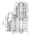
- Fig. 1 is a longitudinal section of a magnet valve apparatus;
- Fig. 2 is a section taken along the line II-II in Fig. 1;
- Fig. 3 is a perspective view of a coil assembly;
- Fig. 4 is an exploded perspective view showing the relationship between a coil member and yoke elements;
- Fig. 5 is a perspective view of an outer frame;
- Fig. 6 is a perspective view of a yoke piece;
- Fig. 7 is an enlarged section taken along the line VII - VII in Fig. 1;
- Fig. 8 is a plane view illustrating the setting up situation of yoke pieces with use of an assembling jig;
- Fig. 9 is a section taken along the line IX - IX in Fig. 8;
- Fig. 10 is a view showing the situation of the coil assembly before being filled up with a filler material;
- Fig. 11 is a longitudinal section of the coil assembly filled up with synthetic resins;
- Fig. 12 is an enlarged fragmental section taken along the line XII- XII in Fig. 11;
- Fig. 13 is a plane view showing a different example of the assembling jig;
- Fig. 14 is a section taken along the line XIV- XIV in Fig. 13;
- Figs. 15 and 16 are longitudinal sections showing different examples of moulds;
- Fig. 17 is a plane view showing a still different jig for assembling the yoke pieces;
- Fig. 18 is a section taken along the line XVIII - XVIII in Fig. 17;
- Fig. 19 is a plane view showing a still different example of the assembling jig for yoke elements;
- Fig. 20 is a plane view showing yoke elements produced by dividing the yoke into a different number of parts;
- Fig. 21 is a perspective view showing a different example of the yoke piece;
- Fig. 22 is an enlarged fragmental view of the yoke piece of Fig. 21;
- Fig. 23 is a view similar to Fig. 7 with the yoke piece therein replaced by that of Fig. 21;
- Fig. 24 is a perspective view showing a still different example of the yoke piece;
- Fig. 25 is an enlarged fragmental section of Fig. 24;
- Fig. 26 is a view similar to Fig. 7 with the yoke piece therein replaced by that of Fig. 24;
- Fig. 27 is a perspective view showing a still different example of the yoke piece;
- Fig. 28 is an enlarged fragmental view of Fig. 27;
- Fig. 29 is a view similar to Fig. 7 with the yoke piece therein replaced by that of Fig. 27;
- Fig. 30 is a longitudinal section showing a different example of the actuator;
- Fig. 31 is an enlarged side elevation of the stator core of Fig. 30;
- Fig. 32 is an enlarged front elevation of the stator core of Fig. 30;
- Fig. 33 is a section taken along the line XXXIII - XXXIII in Fig. 32;
- Fig. 34 is a section taken along the line XXXIV - XXXIV in Fig. 32 and showing-a construction to fix a shading coil in a core main portion;
- Figs. 35 and 36 are perspective views of connection member elements;
- Figs. 37 and 38 are perspective views of core pieces;
- Fig. 39 is a view showing an assembling process of the stator core;
- Fig. 40 is an enlarged side elevation of an armature core of Fig. 30;
- Fig. 41 is an enlarged front elevation of said armature core; and
- Fig. 42 is a section taken along the line XXXXII - XXXXII in Fig. 41.
- In Figs. 1 to 12, a magnet valve apparatus comprises a
valve device 1, anelectromagnet 2 for actuating thevalve device 1 and a terminal box 3 to which the ends of the power supply wires for the electromagnet is connected. For a start, an account is given of thevalve device 1. Abody 4 is provided interiorly with aspace 5 for advance and retreat of aspool 11 and with anoil passage 6. The body is also provided with aport 7 for communication with a hydraulic pressure supply (for example, a pump),ports 8 for communication with a pressure-oil tank, andports aforesaid space 5 for advance and retreat of thespool 11 or with theoil passage 6. In thespace 5, the well knownspool 11 is mounted for right and left travel as viewed in Fig. 1. On either end of thespool 11, aspring seat 12 is capped and aspool restoring spring 13 is compressively inserted between thespring seat 12 and each of threaded connectors of an electromagnet to be described later on. Thesespool restoring springs 13 are mounted for keeping thespool 11 in a neutral position as shown in Fig. 1 and are both compressive. - In the next place, an account is given of the
electromagnet 2. This electromagnet consists of anactuator 16 to operate mechanically theaforementioned valve device 1 and of amagnetizer 17 adapted to impart magnetic flux to theactuator 16. Theactuator 16 has astator core 20 which, at one end thereof, has an integral threadedconnector 21 adapted threadedly in thebody 4 of thevalve device 1. Thestator core 20 has also aflange portion 22 by which a ceiling 0-ring 23 is pressed down. Thestator core 20 has further a throughhole 24 where apush rod 25 is inserted for the right and left displacement as viewed in Fig. 1. One end portion of atube member 26 is capped on the other end portion of thestator core 20 and both the ends portions are hermetically welded to seal off the space inside the tube. Thetube member 26 is made of a nonmagnetic material, defining a space for advance and retreat of thearmature core 31. To the other end portion of thetube member 26 is hermetically welded a blockingmember 27. The blockingmember 27 is provided with a throughhole 28 in which apush pin 29 for manual actuation is inserted for movement to the left of Fig. 1 and return to the shown position. The hermetic seal between the throughhole 28 and thepush pin 29 is maintained by an 0-ring 30. In the space defined by thetube member 26 anarmature core 31 is disposed for the right and left travel in Fig. 1. On a part of the cylindrical surface of thisarmature core 31 anoil passage groove 32 is cut over the full axial length of thearmature core 31 so that oil may flow through thegroove 32 between the left and the right ends of thearmature core 31 as seen in Fig. 1. Theactuator 16 goes by the name of a tube assembly. Next an account is given of themagnetizer 17. Thismagnetizer 17 is situated outside theactuator 16 and is prevented by a stop fitting 18 from departing thevalve device 1. Themagnetizer 17 is provided with ahousing 35, which is made of synthetic resins in one case and is prepared as a die casting in another. Inside the housing 35 acoil assembly 36 is fitted and the space between thecoil assembly 36 and thehousing 35 is filled up with afiller member 37. As the material of thefiller member 37, those synthetic resins are used which are highly electrically insulating and of sufficient heat conduction. Now an account is given of thecoil assembly 36, which comprises acylindrical coil member 38 and ayoke 44 formed so as to enclose the former. Thecoil member 38 consists of acylindrical coil bobbin 39 with a flange at either end thereof and acoil wire 40 covoluted on thebobbin 39. From one of the flanges of thebobbin 39 is extending atongue piece 41 whose tip is provided with aplug holder 42. Alead wire 40a of theaforesaid coil wire 40 is connected to aplug 43 held by theplug holder 42. As a matter of course, thecoil bobbin 39 is made of a material of sufficient electrical insulation and the coil wire is a wire of little electrical resistance, for example, a copper wire. Theyoke 44 consists of plural (two in the present embodiment)yoke elements 45. Eachyoke element 4'5 comprises an auxiliaryouter frame 46 and a plurality ofsimilar yoke pieces 47 arranged radially towards the axis of thecoil member 38. Theouter frame 46 is preferably made of a magnetic material for the outer frame to be utilized as a part of a magnetic circuit but need not be so. Theyoke pieces 47 are necessarily made of a magnetic material. Eachyoke piece 47 formed of anintermediate member 48 to be positioned at the cylindrical surface of thecoil member 38 andend members 49 extending integrally from both ends of theintermediate member 48 as shown in Fig. 6. Theintermediate member 48 is substantially of the same length as the coil member 38 (slightly longer by a clearance for assembling to be described later). - The width of the intermediate member of every yoke piece is selected to be sufficient to pass satisfactorily the magnetic flux generated by the
coil member 38. Theend member 49 has a length equal to the sum of the thickness of thecoil member 38 and the width of theintermediate member 48. The width of the end member (the length thereof along the axis of the coil member 38) is selected to be sufficient to pass the magnetic flux of thecoil member 38. Theintermediate members 48 of all theyoke pieces 47 form a substantially cylindrical yoke portion enclosing thecoil member 38. (In effect, the cylindrical yoke portion has longitudinal cuts but the cuts of such width as that of the present embodiment interfere in no way with the function to conduct magnetic flux.) Theend members 49 ofmany yoke pieces 47 all together form two flange-shaped yoke portions, one connecting magnetically the cylindrical surface of the space for advance and retreat of thearmature core 31 to one end of the aforementioned cylindrical yoke portion, and the other connecting similarly the cylindrical surface of the stator core to the other end of the cylindrical yoke portion. - Further, an account is given of the terminal box 3. This terminal box comprises a
main box 52 and alid 53 put on it, and both are made of an electrically insulating material such as synthetic resins. Themain box 52 consists of abase member 54 andpartition wall members base member 54 together with thepartition wall member 55 is fixed on thebody 4 of thevalve device 1 with fastening screws 57. Between thebase member 54 and thepartition wall member 55 is prepared adisposition space 58 where acontrol circuit 59 is disposed. Thiscircuit 59 includes a plurality ofcircuit components 61, asocket 62,pilot lump 63 and so on all mounted on a printed-circuit board 60. To thesocket 62 theplug 45 is connected detachably as shown clearly in Fig. 1. Thepartition wall member 56 is provided withterminals 64 and as well with anintegral wire inlet 65 through which power supply wires are taken in to be connected to theterminals 64. Thelid 53 is secured on themain box 52 with mountingscrews 66. - Although not shown, the other electromagnet similar to the
aforementioned electromagnet 2 is mounted at the left side of thevlave device 1 as seen in Fig. 1 (only a part of the stator core of the other electromagnet being shown), and a plug of the other electromagnet is connected to asocket 62 provided to the left hand side of thecontrol circuit 59. - When electric power is supplied to the
terminals 64 through the wires taken in from outside in the magnet valve apparatus of the aforementioned construction, the electric power is sent to thecoil wire 40 through thecontrol circuit 59 and further through theplug 43. In this instance, thepilot lamp 63 is lighted in a well known manner. When the electric power is supplied as described above to establish a current in thecoil wire 40, a certain amount of magnetic flux passes through a magnetic circuit consisting of the cylindrical yoke portion of theyoke 44, one of the flange-shaped yoke portion,armature core 31, thestator core 20 and the other flange-shaped yoke portion of theyoke 44. Consequently, thearmature core 31 is pulled towards and moves to thestator core 20. This movement of the armature core is transmitted to thespool 11 by way of thepush rod 25 and thespool 11 is displaced to the left hand side as seen in Fig. 1. In consequence of this, theport 7 communicates with theport 9 and theport 10 with theport 8. - Now, on interruption of the above current, the generation of magnetic flux by the
coil 38 stops and so thearmature core 31 ceases to be pulled by thestator core 20. Then, thespool 11 returns to the neutral position as shown in Fig. 1 under the bias of thespool restoring spring 13 provided at the left of thespool 11. Also, thearmature core 31 is returned to the position as shown in Fig. 1 by the push rod actuated by thespool 11. - When an electric current is turned on in the
coil wire 40 to actuate thearmature core 31 in the aforementioned manner, the eddy current loss in theyoke 44 can be decreased and the energy of the electric current can be used effectively for the operation of thearmature core 31 even if the current is alternating. Namely, when a certain amount of magnetic flux passes through the yoke as the result of the power feed to thecoil wire 40, it is difficult for an eddy current of considerable strength to flow in theyoke 44, which consists ofmany yoke pieces 47 arranged radially, and the eddy current loss in the yoke is small. Thus, electric energy can be used effectively as described above. - Furthermore, when a current is turned on in the
coil wire 40 to operate the electromagnet, the heat generated by thecoil wire 40, if any, can be given off effectively to outer regions of the apparatus. That is, in theyoke 44 enclosing the peripheral surface of thecoil member 38, a number ofyoke pieces 47 are radially arranged. Consequently, the heat generated by thecoil wire 40 is first transmitted from the outer peripheral surface of thecoil member 38 to the inner peripheral edges of theyoke pieces 47 and is directly conducted outwards along the radially disposedyoke pieces 47 to be conveyed to the outer peripheral edges of theyoke pieces 47. Accordingly, the heat generated by the coil can be released from whole the broad outer peripheral surface of theyoke 44. In this manner, the heat in thecoil member 38 can be released effectively. The heat conducted to the outer peripheral edge of eachyoke piece 47 can be brought further to and released at the outer peripheral surface of thehousing 35 by more direct heat conduction due to theouterframe 46, thefiller member 37 and the housing'35. - In the next place, the manufacturing process of the
aforesaid magnetizer 17 is described. Firstly, thehousing 35 and the coil assembly are manufactured separately. Thecoil assembly 36 is manufactured in the following manner. Namely, thecoil wire 40 is fist covolted on thecoil bobbin 39 and thelead wire 40a for thecoil wire 40 is connected to theplug 43, thecoil member 38 as shown in Fig. 4 being formed. On the other hand, theplural yoke elements 45 are made in a separate process other than that for thecoil member 38. For the manufacture of the yoke elements, a necessary number ofouter frames 46 as shown in Fig. 5 are prepared and at the same time a number ofyoke pieces 47 as shown in Fig. 6 are also prepared. Furthermore, an assembling jig is prepared which consists of an enclosingmember 71 as shown in Figs. 8 and 9 and of acenter column 72 adapted in it dismountably along its axis. The diameter of thecenter column 72 is made equal to that of theaforementioned actuator 16. When such a jig has been prepared, theouter frame 46 is first adapted between the enclosingmember 71 and thecenter column 72. Then, a number ofyoke pieces 47 are inserted between theouter frame 46 andcenter column 72 from the upside towards the downside of Fig. 9. After a prescribed number ofyoke pieces 47 have been inserted, the enclosingmember 71 is divided into two along thepartition line 73 of Fig. 8, and theouter frame 46 and a plurality ofyoke pieces 47 having been adapted therein are taken out so that the yoke pieces may not be in bits. Then, theyoke elements 45, having been taken out, are put on thecoil 38 prepared beforehand in the form as shown in Fig. 4 and the form as shown in Fig. 3 is constructed. By the step thus far the assembling of thecoil assembly 36 is completed. In the next place, theaforementioned coil assembly 36 is inserted into thehousing 35. Then, apositioning jig 74 is set in thecoil assembly 36. Thispositioning jig 74 consists of a setting portion adaptable to the outer periphery of the opening side of thehousing 35 and of arod member 76 adapted to be inserted in thecoil assembly 36 and positions thecoil assembly 36 against thehousing 35. Therod member 76 is formed to be as thick as theaforementioned actuator 16. Next, a suitable type of liquid filler material is poured into thehousing 35 through aninjection port 77 formed in thejig 74. This filler material is made to stream in among thecoil member 38,respective yoke pieces 47 and theouter frame 46 in thecoil assembly 36 as well as between.thehousing 35 and thecoil assembly 36. Having been poured, the filler material is solidified. In this solidifying process, the liquid filler material is prevented from streaming out, since thehousing 35 is shut up a forehand with a bottom plate 35a .as shown in Fig. 11. After the filler material has been solidified, thejig 74 as well as the bottom plate 35a is removed. By the step to this point themagnetizer 17 is completed. - If, in pouring the filler material, the
rod member 76 in thepositioning jig 74 is made of a magnetizable material and an electric current is turned on in thecoil member 38 of thecoil assembly 36 throughplugs 43, the following effects can be obtained. That is, as the result of the aforementioned energization of thecoil member 38, therod member 76 is magnetized to become an electromagnet. Consequently, the internal peripheral edges 49a of theend members 49 inmany yoke pieces 47 are pulled by therod member 76 as shown in Fig. 12. In this manner, the internal peripheral edges 49a of theend members 49 inmany yoke pieces 47 are in alignment in good order around the outer peripheral surface of therod member 76. Moreover, the external peripheral edges 49b of theend members 49 are repelling one another to be arranged side by side at regular intervals as shown in Fig. 12, since all of the external peripheral edges 49b are magnetized to be of the same polarity (for example, N pole). Therefore, if the filler material is poured among theyoke pieces 47 in such an alignment and is solidified there,many yoke pieces 47 can be fixed in good order at substantially regular intervals. Furthermore, since the internal peripheral edges 49a in thecoil assembly 36 formed in the aforementioned manner are arranged in good order as described above, the internal peripheral edges 49a in the assembledelectromagnet 2 come to positions very close to thestator core 20 or thearmature core 31 of theactuator 16. Subsequently, the reluctance of the aforementioned magnetic circuit is decreased and a powerful actuating force can be generated in thearmature core 31. Furthermore, the heat generated by thecoil member 38 on energization thereof can be utilized to quicken the solidification of the filler material. - On the other hand, the
actuator 16 is manufactured separately from themagnetizer 17. Namely, thetube member 26 is put on thestator core 20, both are fixed to each other by welding and thearmature core 31 is insertedly mounted in thetube member 26. Further, thepush pin 29 is inserted in the throughhole 28 of the blockingmember 27, which is then fixed to thetube member 26 by welding. Theactuator 16 is thus completed. Next, an account is given of the assembling process of the magnet valve apparatus. First, theactuator 16 is connected to thevalve body 4 by screwing the threadedconnector 21 into the threaded hole of thevalve body 4. Then, themagnetizer 17 is put on the outer peripheral surface of theactuator 16. Astopper member 18, for example a C-shaped ring, is put in aperipheral groove 27a formed on the blockingmember 27, transversely to the axis of the blockingmember 27. Thus, also themagnetizer 17 is fixed relative to thevalve device 1, and the magnet valve apparatus is completed. - Now, Figs. 13 and 14 show a different example of the assembling jig for the yoke elements 46 (unlike that shown in Figs. 8 and 9). In the assembling jig shown in Figs. 13 and 14, an enclosing
member 71e is formed integral with acenter column 72e. If a member in these figures is considered to be the same as or alike to the corresponding one in previous figures, it is given a numeral same as in the previous figures but with an alphabet e and repeated description has been omitted. (In any of the following figures, an alphabet f, g, ----- or so on is successively affixed to a numeral according to the same idea and the repeated description is again omitted.) - Next, Fig. 15 shows a different example of the method for injecting the filler material. In this figure a mould consists of two
members rod member 76f. When the jig of this construction is used, ahousing 35f containing a coil assembly therein is adapted between theelements housing 35f and thecoil assembly 36f through aninjection port 77f and the filler material is solidified. In this case, it is preferable to energize thecoil member 38f throughplugs 43 as in the previous case. After the filler material has been solidified, theelements housing 35f with the aforementioned bottom plate. - In the next place, Fig. 16 shows a still different example of the moulding method of a magnetizer 17g. The moulding according to this Fig. 16 is performed with the mould as shown in Fig. 15. In the case of this example, the moulding is done without using the housing. Namely, a
coil member 38g and a yoke 44g are positioned around acenter column 76g of anelement 79g and, with these kept there,elements coil member 38g through plugs 43g as in the previous case. - Next, Figs. 17 and 18 show a different example of the jig used for the assembling of
yoke elements 45h. This jig consists of anouter frame 81, aninner frame 82 divisible into two sections and acore 83. The assembling of theyoke element 45h with use of such a jig is performed as follows. First, a number ofyoke pieces 47h are arranged and fixed around the core as shown in Fig. 17, and thepieces 47h together with the core 83 are inserted into theinner frame 82 which has been set in theouter frame 81. Then, a bonding agent, for example liquid resins or adhesives, is poured through aninjection port 84 formed between theinner frame 82 and thecore 83. After the bonding agent has settled, theouter frame 81 is first taken off, then theinner frame 82 is divided into two sections and lastly thefinished yoke element 45h is detached from thecore 83. Since all themany yoke pieces 47h in theyoke element 45h finished in this manner are unified rigidly, the works in the next step, i.e. setting the yoke element around the coil member and inserting them into the housing, can be carried out easily. If thecore 83 of the present example is made of a permanent magnet, the work to arrange and fix the many yoke pieces around thecore 83 and to insert them into theinner frame 82 is made easy. Namely, it becomes possible to join (to keep) theplural yoke pieces 47h around thecore 83 under the magnetic force thereof and the many yoke pieces can be prevented from dispersing. Moreover, with use of such a magnetized core, the many yoke pieces can be arranged in good order as in the case described in reference to Fig. 12. - In the next place, Fig. 19 shows a still different example of the assembling jig. This example of the assembling jig differs from that shown in Figs. 17 and 18 in the partition position of an
inner frame 82i. - Next, Fig. 20 shows a different embodiment of the present invention. In this embodiment of Fig. 20, a
yoke 44j is designed to consists of fouryoke elements 45j. Generally speaking, the number of the yoke elements is not limited to 2 of the previous embodiment or 4 of the present embodiment but may be 3 or an arbitrary number more than 3. - In the next place, a different example of the form of the yoke pieces is shown in Figs. 21 and 22. A
yoke piece 47k shown in these figures is so formed that its thickness is decreasing towards the internal peripheral edge, i.e. increasing towards the external peripheral edge. In afinished yoke element 44k as shown in Fig. 28, a plurality of theyoke elements 47k made in this form can be arranged closely without any air gaps. Consequently, a magnetic circuit of a large cross section can be provided and hence the reluctance of it is lowered. Conversely speaking, the radial dimension of the magnetic circuit can be reduced to obtain a magnetic circuit cross section of a certain area and hence it is possible to promote the miniaturization of an electromagnet. In the present example, it is preferable that a silicon steel plate or an ordinary magnetizable steel plate, on which a suitable surface processing is performed for reduction of eddy current, is used as the material of theyoke piece 47k. - Next, in Figs. 24 and 25 is shown an example of the yoke element of still different forms. In these figures, a yoke piece 47ℓ is formed with
space securing projections 86. This projection can be made by protruding a small part of a yoke piece 47t simultaneously when it is died from a metal sheet material (magnetic sheet material). The yoke pieces, each having such aprojection 86, can be arranged systematically at regular intervals. - In Figs. 27 and 28 showing a still different example of the yoke piece, an engage
projection 87 is formed on the top of aspace securing projection 86m, whereas the rear side of thespace securing projection 86m is shaped to present an engagerecess 88. When a yoke element 46m is assembled from theseyoke pieces 47m, they can be unified just by arranging them in such a manner that the engageprojection 87 of one of theyoke pieces 47m may engage with the engagerecess 88 of another of theyoke pieces 47m. Accordingly, the yoke element 46m can be assembled without using the aforementioned outer frame as shown in Fig. 29. - Now, referring to Fig. 30, where a different example of the actuator is shown, an
actuator 98 includes ahollow container 92, which consists of aconnector 93 for connection to the body of the vålve apparatus and of areceiver 94 for receipt of an armature core to be described later. Theconnector 93 is generally made of a magnetic material such as iron but may be made of a nonmagnetic metalic material. Thereceiver 94 consists of acylindrical member 97 adapted to guide the advancing or retreating armature core and of anend member 98 integral with thecylindrical member 97. Thesemembers intermediate cylinder 99 is fixed to one end of thecylindrical member 97 by welding all over the peripheries of both ends. Thisintermediate cylinder 99 is situated inside the coil member and that outside the space for the advance and retreat of the armature core. Subsequently, thisintermediate cylinder 99 is made of a nonmagnetic material in order to prevent that magnetic flux from passing through the structure of theintermediate cylinder 99 which should pass through the armature core and stator core. The other end of thecylinder 99 is fixed to acylindrical portion 96 by welding all over their peripheries. Thus, thehollow container 92 is hermetically sealed. In thehollow container 92, astator 101 is fixedly provided close to theconnector 93 and anarmature core 102 is arranged for advance and retreat to the left and the right in Fig. 30. - Now, a detail account is given of the
stator core 101 referring to Figs. 31 to 38. Thestator core 101 consists of acentral connection member 103 and a coremain portion 104 disposed therearound. Theconnection member 103 consists of twoelements connection member 103 is made of a high strength material such as S10C or S45C. Each of theelements joint portion 107, the cross section of which has a form suitable to constitute a dovetail groove. Theelement 105 is provided, in its central portion, with a throughhole 108 in which theaforementioned push rod 25 is inserted. The coremain portion 104 is constructed by assembling a plurality of suchcore elements core elements central connection member 103. Thecore element 109 is made, for example, of a silicon steel sheet and thecore element 110 of a magnetic steel sheet so that it may be difficult for eddy current to flow in the coremain portion 104. Thecore piece 110 is made thicker towards the outer peripheral side, i.e. thinner towards the inner peripheral side. Consequently, when thecore pieces connection member 103. Both thecore pieces core pieces joint member 111 having a shape conformable to thejoint member 107 of theconnection member 103. The above inner peripheral portion of thecore pieces recess 112. A number of therecesses 112 of all thecore pieces annular groove 113 as shown in Fig. 31. Thecore pieces gain 114 for putting a shading coil therein. Thesegains 114 as well define anannular groove 115 as shown in Fig. 32. In thegroove 115 is embeded ashading coil 116, which is made of a good electrically conducting material such as copper and formed by an arbitrary method such as machining or out. or stanping - Now, the
armature core 102 is described referring to Figs. 40 to 42. Thisarmature core 102 is constructed equivalently to theaforementioned stator core 101. That is, aconnection member 117 consists of twoelements joint portion 120. On the other hand, a coremain portion 121 around theconnection member 117 is formed of a plurality of thosecore pieces 122, each being made of a silicon steel sheet and those core pieces, each being made of a magnetic steel sheet, which are assembled radially about the axis of theconnection member 117. Furthermore, each of thecore pieces joint portion 124, which is coupled with thejoint portion 120 of theconnection member 117. The coremain portion 121 of thearmature core 102 is provided, on its side surface, with anoil passage slot 125 which is cut lengthwise in the longitudinal direction of the armature core, i.e. in the direction of advance or retreat of the armature core. Theslot 125 is formed by sandwichingseveral core pieces 1221 and 123' of smaller radial size between thecore pieces oil passage slot 126 is formed on that end surface of the coremain portion 121 which is opposite to thestator core 101. Thisslot 126 is prepared by reducing the axial length of thecore piece 1221, i.e. by reducing locally the axial length of thearmature core 102 at theslot 126 as clearly shwon in Fig. 42. Furthermore, on theelement 118 of theconnection member 117 in thearmature core 102 is formed anoil passage slot 127 which communicates with the aforementionedoil passage slot 126. The distance L between the inner ends of a pair ofopposting slots 127 is made smaller than the diameter of thepush rod 25. Accordingly, even when thearmature core 102 has been pulled by thestator core 101, a part of theslot 127 can communicate with the throughhole 108 where the working oil flows. - When an electric current is turned on in the coil to actuate the
armature core 102 in the above mentioned construction, the eddy current loss in thestator core 101 and thearmature core 102 due to the electric current, even though an alternate current, can be reduced and the energy of the electric current is used effectively for actuation of thearmature core 102. The reason is as follows. The respective coremain portions stator core 101 and thearmature core 102 are both of laminated construction, in which it is difficult for the eddy current to flow. On the other hand, since either theconnection member connection member respective core radius 1/5, thecross-sectional area 1/25. If the cross-sectional area of the connection member is so much smaller, the generated eddy current is proportionately smaller. For this reason, the eddy current loss in thecores - Moreover, in the above mentioned operation, when the load bearing surface of the
armature core 102, i.e. the surface thereof to abut on thepush rod 25, strikes against thepush rod 25, the reaction force of an impact is exerted on theconnection member 117 by thepush rod 25 in the axial direction (the left and right direction in Fig. 30). The reaction force is applied through thejoint portion 120 and thejoint portion 124 jointed thereto equally on all thepieces many pieces - Furthermore, in the above operation of the armature core, the
push rod 25 advances and retreats repeatedly in the throughhole 108 bored through the central portion of thestator core 101. However, any of thecore pieces push rod 25, since the throughhole 108 is formed in theconnection member 103. Thus, the operation of the apparatus over a long period does not result in relative displacements among the manycore pieces - In the next place, the manufacturing process of the
actuator 90 is described. First thestator core 101 of theactuator 90 is manufactured as follows. Oneelement 105 of the connection member as shown in Fig. 36, oneelement 106 of the connection member as shown in Fig. 36 and a number ofcore pieces 109 as shown in Fig. 37 andcore pieces 110 as shown in Fig. 38 are prepared. Theelement 105 is fixed on thejig 128, prepared in advance, by an arbitrary method as shown in Fig. 9(A). For example, it is fixed by inserting apositioning rod 129 of thejig 128 into the throughhole 108. Then,many pieces element 105 in succession one or several at a time so that the order of arrangment as shown in Fig. 32 may be established. In this case, thejoint member 111 of each core piece is brought into engagement with thejoint member 107 of theelement 105. In the next step, after the prescribed number of the core pieces have been arranged, theelement 106 is thrusted against theelement 105 by a suitable pressing in method so that thejoint member 107 may engage thejoint member 111. After the foregoing procedure, each core piece is prevented from slipping away out of theconnection member 103 by the engagement of thejoint member 111 of each core piece with thejoint member 107 of theconnection member 103. Theelement 106 is securely fixed to theelement 105 by caulking a part indicated by the numeral 130 and the reliable unification between theelements core pieces main portion 104 is processed by polishing (for example by centerless polishing) to be finished to a diameter suitable for tightly fitting in thecylindrical portion 96 of thehollow container 92 and inside theintermediate cylinder 99. Moreover, both the end surfaces of the stator core 101 (the left and the right end surfaces in Fig. 33) are respectively finished to smooth planes by cutting. After or before the polishing and the cutting processes, theshading coil 116 is fitted in thegroove 115. This fitting procedure consists of inserting thecoil 116 into thegroove 115 and deforming a part indicated by anumeral 132 of Fig. 32 to the form as shown in Fig. 34 to make thecoil 116 abut the side surface of thegroove 115 and be fixed therein. In this manner, thestator core 101 is completed. - The assembling of the armature core is performed similarly as in the case of the
aforementioned stator core 101. That is, after the coremain portion 121 has been combined with theconnection member 117, theelements elements pieces numerals main portion 121 is processed by polishing and thearmature core 102 is completed. - On the other hand, the
connection member 93 and thereceiver 94 of thehollow container 92 are formed independently of the above manufacturing work. In forming thereceiver 94, thecylindrical member 97 and theintermediate cylinder 99 are welded together in advance and their internal surfaces are porcessed by polishing so that they may not interfere with the advance and retreat movement of.thearmature core 102. - As a next procedure, the
stator core 101, thearmature core 102, push pins and so on are filled together in thehollow container 62 and thereby theactuator 90 is completed. The first step of this procedure is to fit thestator core 101 into thecylindrical member 96 of theconnector 93. Meanwhile the push pins are inserted into the through holes of thereceiver 94 and besides thearmature core 102 is contained inside thereceiver 94. Then, one end portion of theintermediate cylinder 99 of thereceiver 94 is made to cover thestator core 101. Next, one end edges of thecylindrical portion 96 and theintermediate cylinder 99 of thereceiver 94 are met to each other and welded together all over the periphery. In this case, thegroove 113 of thestator core 101 is situated just inside the contacting edges of thecylindrical portion 96 and theintermediate cylinder 99. Accordingly, when the contacting edges are welded and hence heated, the heat due to welding scarecely diverges from there (the contacting edges are hard to be cooled) and as result of that, the contacting ends can be welded with ease and in addition with good work efficiency. In consequence of the above welding work, a raisedstripe 136 is formed which rises from the contacting edges towards the bottom of thegroove 113 as shown in Fig. 33. This raisedstripe 136, as a matter of cource, is formed all over the circumference of thegroove 113 and thereby that situation is realized where the displacement of thestator core 101 relative to thehollow container 92 is prevented. By the work as proceeds in the foregoing manner, thecylindrical portion 96 and theintermediate cylinder 99 are connected mutually to complete the hermetically sealedhollow container 92 to which, at the same time, is secured thearmature core 101 to complete theactuator 90. - As many apparently widely different embodiments of the present invention may be made without departing from the spirit and scope thereof, it is to be understood that the invention is not limited to the specific embodiments thereof except as defined in the appended claims.
Claims (11)
Applications Claiming Priority (2)
| Application Number | Priority Date | Filing Date | Title |
|---|---|---|---|
| JP196795/83 | 1983-10-19 | ||
| JP19679583A JPS6088410A (en) | 1983-10-19 | 1983-10-19 | Coil assembly of electromagnet and manufacture thereof |
Publications (3)
| Publication Number | Publication Date |
|---|---|
| EP0138408A2 true EP0138408A2 (en) | 1985-04-24 |
| EP0138408A3 EP0138408A3 (en) | 1985-07-31 |
| EP0138408B1 EP0138408B1 (en) | 1988-05-11 |
Family
ID=16363771
Family Applications (1)
| Application Number | Title | Priority Date | Filing Date |
|---|---|---|---|
| EP19840306400 Expired EP0138408B1 (en) | 1983-10-19 | 1984-09-19 | An electromagnet and a method for manufacturing it |
Country Status (3)
| Country | Link |
|---|---|
| EP (1) | EP0138408B1 (en) |
| JP (1) | JPS6088410A (en) |
| DE (1) | DE3471194D1 (en) |
Cited By (6)
| Publication number | Priority date | Publication date | Assignee | Title |
|---|---|---|---|---|
| FR2593432A2 (en) * | 1986-01-30 | 1987-07-31 | Jacobiac Claude | Process for imperviously encapsulating the stator of an electric motor and electric motor obtained using this method |
| DE4201448A1 (en) * | 1992-01-21 | 1993-07-22 | Danfoss As | SUBMERSIBLE MAGNET ARRANGEMENT |
| DE4201449A1 (en) * | 1992-01-21 | 1993-07-22 | Danfoss As | SOLENOID VALVE TOP |
| WO2000074087A1 (en) * | 1999-05-29 | 2000-12-07 | Daimlerchrysler Ag | Actuator for electromagnetic valve control |
| WO2003038844A1 (en) * | 2001-10-22 | 2003-05-08 | Robert Bosch Gmbh | Size-reduced magnet coil carrier |
| US20120038439A9 (en) * | 2009-08-27 | 2012-02-16 | Vacuumschmelze Gmbh & Co., Kg | Laminate Stack Comprising Individual Soft Magnetic Sheets, Electromagnetic Actuator, Process for Their Manufacture and Use of a Soft Magnetic Laminate Stack |
Families Citing this family (2)
| Publication number | Priority date | Publication date | Assignee | Title |
|---|---|---|---|---|
| KR101965266B1 (en) * | 2017-08-02 | 2019-04-03 | 한국알박(주) | Manufacturing method of electromagnet assembly |
| KR102457741B1 (en) * | 2018-12-28 | 2022-10-24 | 한국알박(주) | Electromagnet assembly using in vacuum atmosphere and manufacturing method therof |
Citations (5)
| Publication number | Priority date | Publication date | Assignee | Title |
|---|---|---|---|---|
| GB1344951A (en) * | 1971-01-13 | 1974-01-23 | Philips Electronic Associated | Method of manufacturing inductive components |
| US4004343A (en) * | 1974-04-18 | 1977-01-25 | Expert Industrial Controls Limited | Method of making core tubes for solenoids |
| US4087773A (en) * | 1976-11-15 | 1978-05-02 | Detroit Coil Company | Encapsulated solenoid |
| GB2040585A (en) * | 1978-12-29 | 1980-08-28 | Expert Ind Controls Ltd | Yoke structure for solenoid device |
| DE3209355A1 (en) * | 1982-03-15 | 1983-09-22 | Helmut Dipl.-Ing. 1000 Berlin Schöttle | Plunger armature magnet |
-
1983
- 1983-10-19 JP JP19679583A patent/JPS6088410A/en active Granted
-
1984
- 1984-09-19 EP EP19840306400 patent/EP0138408B1/en not_active Expired
- 1984-09-19 DE DE8484306400T patent/DE3471194D1/en not_active Expired
Patent Citations (5)
| Publication number | Priority date | Publication date | Assignee | Title |
|---|---|---|---|---|
| GB1344951A (en) * | 1971-01-13 | 1974-01-23 | Philips Electronic Associated | Method of manufacturing inductive components |
| US4004343A (en) * | 1974-04-18 | 1977-01-25 | Expert Industrial Controls Limited | Method of making core tubes for solenoids |
| US4087773A (en) * | 1976-11-15 | 1978-05-02 | Detroit Coil Company | Encapsulated solenoid |
| GB2040585A (en) * | 1978-12-29 | 1980-08-28 | Expert Ind Controls Ltd | Yoke structure for solenoid device |
| DE3209355A1 (en) * | 1982-03-15 | 1983-09-22 | Helmut Dipl.-Ing. 1000 Berlin Schöttle | Plunger armature magnet |
Cited By (9)
| Publication number | Priority date | Publication date | Assignee | Title |
|---|---|---|---|---|
| FR2593432A2 (en) * | 1986-01-30 | 1987-07-31 | Jacobiac Claude | Process for imperviously encapsulating the stator of an electric motor and electric motor obtained using this method |
| DE4201448A1 (en) * | 1992-01-21 | 1993-07-22 | Danfoss As | SUBMERSIBLE MAGNET ARRANGEMENT |
| DE4201449A1 (en) * | 1992-01-21 | 1993-07-22 | Danfoss As | SOLENOID VALVE TOP |
| FR2691283A1 (en) * | 1992-01-21 | 1993-11-19 | Danfoss As | Magnetic arrangement with plunger armature. |
| WO2000074087A1 (en) * | 1999-05-29 | 2000-12-07 | Daimlerchrysler Ag | Actuator for electromagnetic valve control |
| WO2003038844A1 (en) * | 2001-10-22 | 2003-05-08 | Robert Bosch Gmbh | Size-reduced magnet coil carrier |
| US6816050B2 (en) | 2001-10-22 | 2004-11-09 | Robert Bosch Gmbh | Size-reduced magnet coil carrier |
| US20120038439A9 (en) * | 2009-08-27 | 2012-02-16 | Vacuumschmelze Gmbh & Co., Kg | Laminate Stack Comprising Individual Soft Magnetic Sheets, Electromagnetic Actuator, Process for Their Manufacture and Use of a Soft Magnetic Laminate Stack |
| US8669837B2 (en) * | 2009-08-27 | 2014-03-11 | Vacuumschmelze Gmbh & Co. Kg | Laminate stack comprising individual soft magnetic sheets, electromagnetic actuator, process for their manufacture and use of a soft magnetic laminate stack |
Also Published As
| Publication number | Publication date |
|---|---|
| EP0138408A3 (en) | 1985-07-31 |
| DE3471194D1 (en) | 1988-06-16 |
| JPS6088410A (en) | 1985-05-18 |
| JPH0314209B2 (en) | 1991-02-26 |
| EP0138408B1 (en) | 1988-05-11 |
Similar Documents
| Publication | Publication Date | Title |
|---|---|---|
| US4087773A (en) | Encapsulated solenoid | |
| EP2528074B1 (en) | Ignition coil for internal combustion engine | |
| JP4403556B2 (en) | solenoid valve | |
| JPS61136071A (en) | Solenoid operated valve | |
| EP2766649B1 (en) | Solenoid valve with a metallic tube bobbin | |
| WO1991011605A3 (en) | Electromagnetically operated valve | |
| EP0138408B1 (en) | An electromagnet and a method for manufacturing it | |
| JP2001143924A (en) | Electromagnet | |
| US4677327A (en) | Electromagnetic actuator with concentric coil resin fill | |
| JP3219611B2 (en) | Three-way solenoid valve and method of assembling the same | |
| JPH05263958A (en) | Electromagnetic valve top part | |
| US5280873A (en) | Plunger armature magnetic arrangement | |
| US4236131A (en) | Electromagnet with plunger-type armature and a method for the production thereof | |
| KR102344692B1 (en) | Solenoid | |
| JP3017702B2 (en) | solenoid | |
| JP3782850B2 (en) | Solenoid coil assembly | |
| US3605054A (en) | Encapsulated alternating current solenoid | |
| JP2001141098A (en) | Solenoid valve | |
| JP2006226263A (en) | Electromagnetic driving device and fuel injection valve using this device | |
| US20200328018A1 (en) | Electromagnetic actuator and method for manufacturing same | |
| CN114110238B (en) | Stator assembly of water inlet electromagnetic valve and water inlet electromagnetic valve | |
| JPH09119544A (en) | Electromagnet device | |
| JP3811835B2 (en) | solenoid | |
| CN220566585U (en) | Pilot structure and external pilot electromagnetic valve | |
| CN115143204B (en) | Electromagnetic coupling device |
Legal Events
| Date | Code | Title | Description |
|---|---|---|---|
| PUAI | Public reference made under article 153(3) epc to a published international application that has entered the european phase |
Free format text: ORIGINAL CODE: 0009012 |
|
| AK | Designated contracting states |
Designated state(s): CH DE FR GB IT LI |
|
| PUAL | Search report despatched |
Free format text: ORIGINAL CODE: 0009013 |
|
| AK | Designated contracting states |
Designated state(s): CH DE FR GB IT LI |
|
| 17P | Request for examination filed |
Effective date: 19851009 |
|
| 17Q | First examination report despatched |
Effective date: 19861204 |
|
| ITF | It: translation for a ep patent filed | ||
| GRAA | (expected) grant |
Free format text: ORIGINAL CODE: 0009210 |
|
| AK | Designated contracting states |
Kind code of ref document: B1 Designated state(s): CH DE FR GB IT LI |
|
| REF | Corresponds to: |
Ref document number: 3471194 Country of ref document: DE Date of ref document: 19880616 |
|
| ET | Fr: translation filed | ||
| PLBE | No opposition filed within time limit |
Free format text: ORIGINAL CODE: 0009261 |
|
| STAA | Information on the status of an ep patent application or granted ep patent |
Free format text: STATUS: NO OPPOSITION FILED WITHIN TIME LIMIT |
|
| 26N | No opposition filed | ||
| ITTA | It: last paid annual fee | ||
| PGFP | Annual fee paid to national office [announced via postgrant information from national office to epo] |
Ref country code: FR Payment date: 19940727 Year of fee payment: 11 |
|
| PGFP | Annual fee paid to national office [announced via postgrant information from national office to epo] |
Ref country code: CH Payment date: 19940811 Year of fee payment: 11 |
|
| PGFP | Annual fee paid to national office [announced via postgrant information from national office to epo] |
Ref country code: GB Payment date: 19940905 Year of fee payment: 11 |
|
| PGFP | Annual fee paid to national office [announced via postgrant information from national office to epo] |
Ref country code: DE Payment date: 19940927 Year of fee payment: 11 |
|
| PG25 | Lapsed in a contracting state [announced via postgrant information from national office to epo] |
Ref country code: GB Effective date: 19950919 |
|
| PG25 | Lapsed in a contracting state [announced via postgrant information from national office to epo] |
Ref country code: LI Effective date: 19950930 Ref country code: CH Effective date: 19950930 |
|
| GBPC | Gb: european patent ceased through non-payment of renewal fee |
Effective date: 19950919 |
|
| REG | Reference to a national code |
Ref country code: CH Ref legal event code: PL |
|
| PG25 | Lapsed in a contracting state [announced via postgrant information from national office to epo] |
Ref country code: FR Effective date: 19960531 |
|
| PG25 | Lapsed in a contracting state [announced via postgrant information from national office to epo] |
Ref country code: DE Effective date: 19960601 |
|
| REG | Reference to a national code |
Ref country code: FR Ref legal event code: ST |