EP0137625B1 - Transport of prefabricated offshore structures - Google Patents
Transport of prefabricated offshore structures Download PDFInfo
- Publication number
- EP0137625B1 EP0137625B1 EP84305436A EP84305436A EP0137625B1 EP 0137625 B1 EP0137625 B1 EP 0137625B1 EP 84305436 A EP84305436 A EP 84305436A EP 84305436 A EP84305436 A EP 84305436A EP 0137625 B1 EP0137625 B1 EP 0137625B1
- Authority
- EP
- European Patent Office
- Prior art keywords
- barge
- vessel
- deck
- offshore structure
- prefabricated
- Prior art date
- Legal status (The legal status is an assumption and is not a legal conclusion. Google has not performed a legal analysis and makes no representation as to the accuracy of the status listed.)
- Expired
Links
- XLYOFNOQVPJJNP-UHFFFAOYSA-N water Substances O XLYOFNOQVPJJNP-UHFFFAOYSA-N 0.000 claims description 29
- 238000004519 manufacturing process Methods 0.000 claims description 22
- 238000000034 method Methods 0.000 claims description 9
- 238000009434 installation Methods 0.000 claims description 8
- 238000010276 construction Methods 0.000 description 3
- 230000001133 acceleration Effects 0.000 description 2
- 230000001934 delay Effects 0.000 description 2
- 238000005553 drilling Methods 0.000 description 2
- 239000004215 Carbon black (E152) Substances 0.000 description 1
- 230000002349 favourable effect Effects 0.000 description 1
- 238000005188 flotation Methods 0.000 description 1
- 230000005484 gravity Effects 0.000 description 1
- 229930195733 hydrocarbon Natural products 0.000 description 1
- 150000002430 hydrocarbons Chemical class 0.000 description 1
- 238000011084 recovery Methods 0.000 description 1
- 238000004513 sizing Methods 0.000 description 1
- 239000003643 water by type Substances 0.000 description 1
Images



Classifications
-
- B—PERFORMING OPERATIONS; TRANSPORTING
- B63—SHIPS OR OTHER WATERBORNE VESSELS; RELATED EQUIPMENT
- B63B—SHIPS OR OTHER WATERBORNE VESSELS; EQUIPMENT FOR SHIPPING
- B63B21/00—Tying-up; Shifting, towing, or pushing equipment; Anchoring
-
- B—PERFORMING OPERATIONS; TRANSPORTING
- B63—SHIPS OR OTHER WATERBORNE VESSELS; RELATED EQUIPMENT
- B63B—SHIPS OR OTHER WATERBORNE VESSELS; EQUIPMENT FOR SHIPPING
- B63B35/00—Vessels or similar floating structures specially adapted for specific purposes and not otherwise provided for
- B63B35/003—Vessels or similar floating structures specially adapted for specific purposes and not otherwise provided for for transporting very large loads, e.g. offshore structure modules
Definitions
- This invention relates to the transport of prefabricated offshore structures, for example drill jackets.
- a drill jacket is an elongated offshore structure made up of a plurality of tubular members with cross bracing.
- the structure is installed by lowering it to rest on the sea bottom.
- the jacket is secured in this position and functions to support a deck unit and hydrocarbon production equipment above the water line.
- the deck unit which usually comprises a flat deck area with a plurality of legs extending downwardly therefrom, provides support for oil drilling and recovery equipment. These components make up an offshore facility.
- Offshore facility components may often be built more economically at fully integrated fabrication yards. However, due to existing favorable conditions at such fabrication yards and the quantity thereof being limited by the cost of building them, such fabrication yards may be located at extreme distances from the final offshore facility locations. The technical and safety risks of long tows, however, make it difficult for these remote yards to compete with fabrication yards located near the final offshore facility sites. Shallow draft barges for loading offshore structures in the typically shallow waters, because of the size and bulk of such structures, may be unstable in open sea thus requiring periods of calm weather for towing safety and, therefore, long delays may be experienced while waiting for these calm conditions. On long tows such as over an ocean, there is also no assurance, as previously noted, that good weather and calm seas will prevail throughout the transport. Rough seas may in addition cause severe fatigue or other damage to the offshore components during a tow by barge.
- the fatigue stresses during such transport are increased with higher accelerations during the roll of the transport structure.
- Barges typically have a low period of roll with resulting high accelerations during the roll as compared to a self-propelled sea-going vessel.
- the total fatigue stresses on an offshore structure during a transport of specified length is related to the duration of transport.
- the speed of a barge being towed is typically slow as compared to the speed of a self-propelled sea-going vessel resulting typically in more than twice as many fatigue cycles when an offshore structure is towed by barge.
- French Patent Application Publication No.. FR-A-2 508 410 discloses a marine transport system corresponding to the pre-characterizing part of claim 2, comprising a sea-going self-propelled vessel having a well deck and a raised deck with means in the vessel for submerging the well deck to a selected depth without submerging the raised deck; and a floating object having a draft which is less than said selected depth and a length which is less than a length of the well deck, the floating object being disposed on the well deck.
- a method of loading a prefabricated offshore structure for transport from a fabrication yard adjacent shallow water to a final site for installation comprising:
- the invention also provides a marine transport system comprising:
- the invention can be so embodied, as described hereinbelow, as a system and method that can provide one or more of the following advantageous features.
- a system for transporting large bulky prefabricated offshore structures such as, for example, drill jacket 10 utilizing a sea-going self-propelled vessel such as the ship generally designated 12.
- the ship 12 includes a power plant for propulsion as well as ballasting equipment for submerging a mid or well deck 14 to a level which is below the draft of a shallow draft barge 16.
- Ship 12 includes raised forward and aft decks 18 and 20 respectively.
- decks 18 and 20 are provided with a height to remain above the water line and are suitably sized, in accordance with principles of common knowledge to those of ordinary skill in the art to which this invention pertains, to maintain stability and flotation of the vessel while mid deck 14 is submerged to a depth for barge 16 with jacket 10 to be floated over the top of the deck 14.
- a fixed suitable connection means may be provided for securing the barge 16 to vessel 12 such as the at least four point tie-down system illustrated at 24.
- a drill jacket is used as an example herein, this invention is meant to include procedures and apparatus for transporting various other prefabricated offshore structures such as decks or modules.
- a fabrication yard 40 is illustrated adjacent shallow water 42 which is sufficiently deep for shallow draft barge 16, but has insufficient depth for positioning ship 12 for loading of a drill jacket 10 directly onto the ship.
- the drill jacket 10 is discharged from the fabrication yard 40 onto barge 16 which in turn is towed into deep water (that is; water which is sufficiently deep for a sea-going self-propelled vessel such as ship 12 shown in Fig. 4) for loading onto ship 12 as will hereinafter be described.
- drill jacket 10 is shown being skidded onto shallow draft barge 16 by means such as portable load-out rails or guides 28.
- Jacket 10 is provided with a plurality of skids 30 which slide along rails 28 and, at the interface between bulkhead 32 and barge 16, onto rails or tracks 34 on the top surface of the barge 16.
- Fig. 3 shows the loading of an offshore drilling platform deck unit 36 onto a barge 16.
- rails 28 and tracks 34 are utilized on which skids slide to support the downwardly extending legs 38 of deck unit 36.
- ballast tanks schematically indicated at 47 to submerge its mid deck 14.
- Figs. 6, 7, and 8 show the relative positions of the barge 16 and ship 12 as the two structures are combined to form a single ocean going unit 44.
- barge 16 is shown floating over the deck 14 which has been submerged to a selected depth sufficient for floating of the barge thereover.
- the vessel 12 is then deballasted to raise the deck 14 above the water line and raise barge 16 with its drill jacket load 10.
- the vessel 12 should preferably be sufficiently large and stable to support the barge and oversized load during typical rough seas and weather conditions, and such sizing can be determined utilizing principles of common knowledge to those of ordinary skill in the art to which this invention pertains.
- the height of the offshore structure above the water level is less than the overall height of the barge. This is illustrative of the height of the offshore structure during a typical tow by barge.
- the offshore structure loaded barge is loaded onto the ship as shown in Fig. 8
- the height of the offshore structure above the water is increased so that its height is greater than the overall barge height so that the offshore structure may be disposed higher than and thus out of the way of the waves during rougher seas to thus minimize risk of damage to the offshore structure.
- Figs. 9 and 10 show the orientation of barge 16 on the vessel 12.
- tie-down connections between the barge 16 and vessel 12 are disconnected, vessel 12 is reballasted to float barge 16 which can then be easily towed away from vessel 12 and to the desired location for launching jacket 10.
- Fig. 11 shows the barge 16 specially outfitted with a pivot support 54 for launching the jacket 10.
- jacket 10 is slid rearwardly on barge 16 so that its center of gravity moves onto support 54.
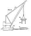
- a deck unit 36 can be off-loaded from barge 16 using a crane 56 mounted on a derrick or construction barge 58 which is anchored at the offshore site: see Figs. 12 and 13. With jacket 10 already in place, crane 56 is utilized to lift deck 36 from barge 16 and lower it onto the top of jacket 10.
- the maximum height of the vessel and barge system is equal to the height illustrated at 15 of the top surface 22 of the barge 16 when the barge is disposed on the well deck 14.
- all deck houses and other structures on forward and aft decks 18 and 20 have a height no higher than the supporting surfaces 22 on top of barge 16 which support lower segments of jacket 10.
- the elongated jacket 10 can extend beyond the length of barge 16 and over the forward and aft decks 18 and 20 and may extend beyond the forward and aft ends of the vessel.
- deck supports 26 may also be provided on forward and aft decks 18 and 20 respectively for supporting the overhanging portions of jacket 10 to further reduce stresses experienced by the jacket during rough sea conditions.
- a vessel and barge system embodying the present invention may comprise, for example, a sea going vessel 12 of about 320 m (1050 feet) in length with a mid-deck 14 of about 213 m (700 feet) in length.
- Mid deck 14 may be approximately 53 to 69 m (175 to 225 feet) wide.
- Such a size may be provided by a converted tanker having a dry weight tonnage of 230,000.
- a 198 m (650 foot) barge 16 having a width of 52 m (170 feet) may be provided to carry a jacket 10 of 40,640 tonnes (40,000 tons).
- Such a combined structure may deliver the jacket at a cruising speed of about 7.2 m/s (14 knots) or more.
- the shallow draft barge 16 may operate in as little as 7.6 m (25 feet) of water for loading of a drill jacket at a fabrication yard near shallow water.
- an offshore structure may be prefabricated at a fabrication yard near shallow water and then provided with quick, safe, and reliable transportation over an ocean.
Landscapes
- Engineering & Computer Science (AREA)
- Chemical & Material Sciences (AREA)
- Combustion & Propulsion (AREA)
- Mechanical Engineering (AREA)
- Ocean & Marine Engineering (AREA)
- Transportation (AREA)
- Earth Drilling (AREA)
- Ship Loading And Unloading (AREA)
- Reinforced Plastic Materials (AREA)
- Revetment (AREA)
- Curing Cements, Concrete, And Artificial Stone (AREA)
Description
- This invention relates to the transport of prefabricated offshore structures, for example drill jackets.
- A drill jacket is an elongated offshore structure made up of a plurality of tubular members with cross bracing. The structure is installed by lowering it to rest on the sea bottom. The jacket is secured in this position and functions to support a deck unit and hydrocarbon production equipment above the water line. The deck unit, which usually comprises a flat deck area with a plurality of legs extending downwardly therefrom, provides support for oil drilling and recovery equipment. These components make up an offshore facility.
- The manufacture of prefabricated components of such an offshore facility has in the past required that the fabrication yards or sites be built relatively close to a final desired location for the facility. Most of these yards are located near shallow water areas. When components are fabricated in such yards, the components may be loaded onto barges having shallow drafts. The barges are then towed to the final location for installation of the facility. Such a procedure, in accordance with the pre-characterizing part of
claim 1, may be reliably accomplished safely if the seas are calm and if the duration of such a tow is no more than a day or two, since weather forecasts for such short durations are usually fairly reliable. However, even though a tow may be of short duration, long delays may be experienced while waiting for calm seas. When these tows do arrive at the installation site, the barges may be moored in shallow water alongside the construction equipment at the site, which equipment may include, for example cranes mounted on flat barges. - Offshore facility components may often be built more economically at fully integrated fabrication yards. However, due to existing favorable conditions at such fabrication yards and the quantity thereof being limited by the cost of building them, such fabrication yards may be located at extreme distances from the final offshore facility locations. The technical and safety risks of long tows, however, make it difficult for these remote yards to compete with fabrication yards located near the final offshore facility sites. Shallow draft barges for loading offshore structures in the typically shallow waters, because of the size and bulk of such structures, may be unstable in open sea thus requiring periods of calm weather for towing safety and, therefore, long delays may be experienced while waiting for these calm conditions. On long tows such as over an ocean, there is also no assurance, as previously noted, that good weather and calm seas will prevail throughout the transport. Rough seas may in addition cause severe fatigue or other damage to the offshore components during a tow by barge.
- The fatigue stresses during such transport are increased with higher accelerations during the roll of the transport structure. Barges typically have a low period of roll with resulting high accelerations during the roll as compared to a self-propelled sea-going vessel. Furthermore, the total fatigue stresses on an offshore structure during a transport of specified length is related to the duration of transport. The speed of a barge being towed is typically slow as compared to the speed of a self-propelled sea-going vessel resulting typically in more than twice as many fatigue cycles when an offshore structure is towed by barge. Thus, in calm seas as well as rough seas, the number of and severity of fatigue stresses on an offshore structure being towed by barge may be much greater, resulting in increased risk of damage over what would be the case if the offshore structure were being carried by a sea-going vessel over the same distance.
- Since a barge deck is typically low in the water, an offshore structure is subjected undesirably to the stressful pounding of waves thereagainst. This of course becomes more of a problem as the length of tow is increased and as the seas become rougher. It is thus desirable to raise an offshore structure so that it is disposed higher than and thus out of the way of the waves during a typical storm as well as during other weather conditions.
- Since the fabrication yards are usually located near shallow water, ships for carrying such structures may typically be incapable of getting close enough .for loading of the structures directly thereon. In addition, such prefabricated offshore structures may be longer and/or wider than the ships on which it is desirable to load them.
- French Patent Application Publication No.. FR-A-2 508 410 discloses a marine transport system corresponding to the pre-characterizing part of claim 2, comprising a sea-going self-propelled vessel having a well deck and a raised deck with means in the vessel for submerging the well deck to a selected depth without submerging the raised deck; and a floating object having a draft which is less than said selected depth and a length which is less than a length of the well deck, the floating object being disposed on the well deck.
- According to the invention there is provided a method of loading a prefabricated offshore structure for transport from a fabrication yard adjacent shallow water to a final site for installation, the method comprising:
- floating a barge to a position adjacent the fabrication yard;
- transferring the offshore structure from the fabrication yard onto the barge; and
- floating the barge to a deep water area;
- sailing a self-propelled transport vessel to the deep water area adjacent the barge, the vessel having a mid deck and at least one deck raised above the mid deck;
- maintaining the raised deck above water level while ballasting the vessel to submerge the mid deck to a depth which is equal at least to the draft of the barge with the offshore structure disposed thereon;
- floating the barge over the submerged mid deck;
- deballasting the vessel to raise the mid deck above water level to support the barge-and the offshore structure; and
- securing the barge to the vessel and securing the offshore structure on the barge whereby the offshore structure may be transported over an ocean to a final site for installation;
- the vessel and barge being sized such that the maximum height of the vessel and barge system is equal to the height of the top surface of the barge when the barge is disposed on the mid deck whereby the prefabricated offshore structure may extend over the entire length of the vessel.
- The invention also provides a marine transport system comprising:
- a sea-going self-propelled vessel having a well deck and a raised deck with means in the vessel for submerging the well deck to a selected depth without submerging the raised deck;
- a floating object having a draft which is less than said selected depth and a length which is less than a length of the well deck, the floating object being disposed on the well deck; and
- the system being characterised in that:
- the floating object is a barge having a top surface for supporting a prefabricated offshore structure;
- means is provided on the barge for skidding a prefabricated offshore structure onto the barge;
- means is provided for securing the barge to the vessel and for securing a prefabricated offshore structure on the barge for ocean transport of the offshore structure; and
- the maximum height of the vessel and barge system is equal to the height of the top surface of the barge when disposed on the well deck whereby a loaded prefabricated offshore structure may extend over the entire length of the vessel.
- The invention can be so embodied, as described hereinbelow, as a system and method that can provide one or more of the following advantageous features.
- (i) They can provide long distance ocean transport of prefabricated offshore structures which is both fast and safe, thus ensuring that the components arrive undamaged and on time.
- (ii) They can provide quick, safe, and reliable transportation over an ocean of prefabricated offshore structures from a fabrication yard near shallow water.
- (iii) They can minimize the number of and severity of fatigue stresses on an offshore structure during ocean transport thereof so as to minimize the risk of damage to the offshore structure.
- (iv) They can raise an offshore structure for ocean transport so that it is disposed higher than and thus out of the way of the waves during a typical storm to thus minimize risk of damage to the offshore structure.
- (v) They can enable transportation of a prefabricated offshore structure which is longer than the length of a ship used in the transportation.
- (vi) They can provide more efficient transport of bulky prefabricated offshore structures.
- (vii) They can render it practical and commercially advantageous to utilize any suitably outfitted fabrication yard or site to manufacture large bulky offshore structures for installation at desired offshore sites anywhere in the world.
- The invention will now be further described, by way of illustrative and non-limiting example, with reference to the accompanying drawings, in which:
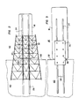
- Fig. 1 is a perspective view of a system embodying the invention with a prefabricated offshore structure loaded thereon for transport;
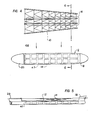
- Fig. 2 is a top plan view illustrating the loading of a jacket from a fabrication yard onto a shallow draft barge;
- Fig. 3 is a view similar to Fig. 2 illustrating the loading of a deck unit;
- Fig. 4 is a top plan view showing the orientation of a barge loaded with a prefabricated offshore structure to a transport vessel before the barge is floated onto a mid deck of the vessel;
- Fig. 5 is a side elevational view of the transport vessel with its mid deck submerged;
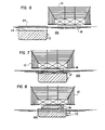
- Fig. 6 is an enlarged sectional view taken along line 6-6 of Fig. 4;
- Fig. 7 is a sectional view similar to Fig. 6 with the barge shown positioned over the vessel mid deck;
- Fig. 8 is a view similar to Fig. 7 after the transport has been floated to support the barge loaded with the prefabricated offshore structure;
- Fig. 9 is a top plan view of the vessel with barge and prefabricated offshore structure assembled for ocean transport;
- Fig. 10 is a side elevational view of the embodiment shown in Fig. 9;
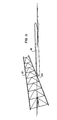
- Fig. 11 is a side elevational view showing an intermediate position during the launching of a jacket from a specially designed shallow draft barge;
- Fig. 12 is a side elevational view of equipment used in off-loading a shallow draft barge used in accordance with the invention; and
- Fig. 13 is a top plan view showing the relative size and orientation of a shallow draft barge used in accordance with the invention and a construction barge for off-loading the shallow draft barge.
- Referring to Fig. 1, there is shown a system for transporting large bulky prefabricated offshore structures such as, for example,
drill jacket 10 utilizing a sea-going self-propelled vessel such as the ship generally designated 12. Theship 12 includes a power plant for propulsion as well as ballasting equipment for submerging a mid orwell deck 14 to a level which is below the draft of ashallow draft barge 16.Ship 12 includes raised forward andaft decks decks mid deck 14 is submerged to a depth forbarge 16 withjacket 10 to be floated over the top of thedeck 14. A fixed suitable connection means may be provided for securing thebarge 16 tovessel 12 such as the at least four point tie-down system illustrated at 24. Although a drill jacket is used as an example herein, this invention is meant to include procedures and apparatus for transporting various other prefabricated offshore structures such as decks or modules. - In both Figs. 2 and 3, a
fabrication yard 40 is illustrated adjacentshallow water 42 which is sufficiently deep forshallow draft barge 16, but has insufficient depth forpositioning ship 12 for loading of adrill jacket 10 directly onto the ship. In order to loaddrill jacket 10 onto a sea-going vessel for safe and fast ocean transport to an installation site, thedrill jacket 10 is discharged from thefabrication yard 40 ontobarge 16 which in turn is towed into deep water (that is; water which is sufficiently deep for a sea-going self-propelled vessel such asship 12 shown in Fig. 4) for loading ontoship 12 as will hereinafter be described. - In Fig. 2,
drill jacket 10 is shown being skidded ontoshallow draft barge 16 by means such as portable load-out rails or guides 28.Jacket 10 is provided with a plurality ofskids 30 which slide alongrails 28 and, at the interface betweenbulkhead 32 andbarge 16, onto rails or tracks 34 on the top surface of thebarge 16. Fig. 3 shows the loading of an offshore drillingplatform deck unit 36 onto abarge 16. Here again, rails 28 and tracks 34 are utilized on which skids slide to support the downwardly extendinglegs 38 ofdeck unit 36. - After it is loaded,
barge 16 is floated andvessel 12 is sailed into the positions shown in Fig. 4 in deep water with respect to each other and, as shown in Fig. 5,vessel 12 is ballasted by means such as ballast tanks schematically indicated at 47 to submerge itsmid deck 14. - Figs. 6, 7, and 8 show the relative positions of the
barge 16 andship 12 as the two structures are combined to form a singleocean going unit 44. In Fig. 7,barge 16 is shown floating over thedeck 14 which has been submerged to a selected depth sufficient for floating of the barge thereover. As shown in Fig. 8, thevessel 12 is then deballasted to raise thedeck 14 above the water line and raisebarge 16 with itsdrill jacket load 10. Thevessel 12 should preferably be sufficiently large and stable to support the barge and oversized load during typical rough seas and weather conditions, and such sizing can be determined utilizing principles of common knowledge to those of ordinary skill in the art to which this invention pertains. - When loaded on the barge as shown in Fig. 6, the height of the offshore structure above the water level is less than the overall height of the barge. This is illustrative of the height of the offshore structure during a typical tow by barge. When the offshore structure loaded barge is loaded onto the ship as shown in Fig. 8, the height of the offshore structure above the water is increased so that its height is greater than the overall barge height so that the offshore structure may be disposed higher than and thus out of the way of the waves during rougher seas to thus minimize risk of damage to the offshore structure.
- Figs. 9 and 10 show the orientation of
barge 16 on thevessel 12. For launching thejacket 10, tie-down connections between thebarge 16 andvessel 12 are disconnected,vessel 12 is reballasted to floatbarge 16 which can then be easily towed away fromvessel 12 and to the desired location for launchingjacket 10. - Fig. 11 shows the
barge 16 specially outfitted with apivot support 54 for launching thejacket 10. To accomplish this,jacket 10 is slid rearwardly onbarge 16 so that its center of gravity moves ontosupport 54. With suitable ballasting ofbarge 16 while maintaining its stability in accordance with principles of common knowledge to those of ordinary skill in the art to which this invention pertains,jacket 10 is rotated into the water through the pivoting ofsupport 54 thereby launching the jacket into the sea at the desired location. Adeck unit 36 can be off-loaded frombarge 16 using acrane 56 mounted on a derrick orconstruction barge 58 which is anchored at the offshore site: see Figs. 12 and 13. Withjacket 10 already in place,crane 56 is utilized to liftdeck 36 frombarge 16 and lower it onto the top ofjacket 10. - Referring back to Fig. 1, in order to transport a prefabricated offshore structure which, as is sometimes the case, has a length greater than the length of the transporter vessel, the maximum height of the vessel and barge system is equal to the height illustrated at 15 of the
top surface 22 of thebarge 16 when the barge is disposed on thewell deck 14. In other words, all deck houses and other structures on forward andaft decks surfaces 22 on top ofbarge 16 which support lower segments ofjacket 10. In this way, theelongated jacket 10 can extend beyond the length ofbarge 16 and over the forward andaft decks down system 24, deck supports 26 may also be provided on forward andaft decks jacket 10 to further reduce stresses experienced by the jacket during rough sea conditions. - A vessel and barge system embodying the present invention may comprise, for example, a
sea going vessel 12 of about 320 m (1050 feet) in length with a mid-deck 14 of about 213 m (700 feet) in length.Mid deck 14 may be approximately 53 to 69 m (175 to 225 feet) wide. Such a size may be provided by a converted tanker having a dry weight tonnage of 230,000. A 198 m (650 foot)barge 16 having a width of 52 m (170 feet) may be provided to carry ajacket 10 of 40,640 tonnes (40,000 tons). Such a combined structure may deliver the jacket at a cruising speed of about 7.2 m/s (14 knots) or more. While such a vessel may require a water depth for loading and unloading operations of 35 m (115 feet) or more, theshallow draft barge 16 may operate in as little as 7.6 m (25 feet) of water for loading of a drill jacket at a fabrication yard near shallow water. Thus, an offshore structure may be prefabricated at a fabrication yard near shallow water and then provided with quick, safe, and reliable transportation over an ocean.
and the method being characterised by:
Claims (7)
and the method being characterised by:
the system being characterised in that:
Applications Claiming Priority (2)
| Application Number | Priority Date | Filing Date | Title |
|---|---|---|---|
| US52207083A | 1983-08-10 | 1983-08-10 | |
| US522070 | 1983-08-10 |
Publications (2)
| Publication Number | Publication Date |
|---|---|
| EP0137625A1 EP0137625A1 (en) | 1985-04-17 |
| EP0137625B1 true EP0137625B1 (en) | 1987-09-30 |
Family
ID=24079341
Family Applications (1)
| Application Number | Title | Priority Date | Filing Date |
|---|---|---|---|
| EP84305436A Expired EP0137625B1 (en) | 1983-08-10 | 1984-08-09 | Transport of prefabricated offshore structures |
Country Status (7)
| Country | Link |
|---|---|
| EP (1) | EP0137625B1 (en) |
| JP (1) | JPS6175090A (en) |
| KR (1) | KR850001878A (en) |
| BR (1) | BR8404004A (en) |
| DE (1) | DE3466507D1 (en) |
| ES (2) | ES535016A0 (en) |
| IN (1) | IN160785B (en) |
Families Citing this family (5)
| Publication number | Priority date | Publication date | Assignee | Title |
|---|---|---|---|---|
| WO2003086852A1 (en) * | 2002-04-10 | 2003-10-23 | Itrec B.V. | Submersible watercraft |
| CN102242544A (en) * | 2010-05-14 | 2011-11-16 | 中国海洋石油总公司 | Movable pushing device for sliding launch of large jacket |
| CN109372275B (en) * | 2018-12-17 | 2023-11-03 | 北京城建集团有限责任公司 | High-altitude light-weight attached lattice type suspension arm device and construction method thereof |
| CN115123463B (en) * | 2022-07-05 | 2023-11-14 | 上海外高桥造船有限公司 | Temporary sea binding structure of large ship superstructure and sea binding method thereof |
| CN116812085A (en) * | 2023-03-23 | 2023-09-29 | 海洋石油工程股份有限公司 | Method for tugging and loading jacket |
Family Cites Families (7)
| Publication number | Priority date | Publication date | Assignee | Title |
|---|---|---|---|---|
| FR1400750A (en) * | 1964-06-09 | 1965-05-28 | Mitsui Shipbuilding Eng | Process for the loading and unloading of a transport cargo vessel of containers or the like and cargo for the application of the preceding process or the like |
| US3508514A (en) * | 1966-04-04 | 1970-04-28 | Vienna Arthur W | Cargo ships |
| US3399792A (en) * | 1967-04-10 | 1968-09-03 | George W. Chester | Loading barges onto ships using drydocks |
| JPS52124684A (en) * | 1976-04-13 | 1977-10-19 | Nippon Kokan Kk <Nkk> | Assembling type cargo ship |
| US4086777A (en) * | 1976-12-13 | 1978-05-02 | Standard Oil Company (Indiana) | Apparatus for launching battered leg jackets for offshore platforms |
| JPS56122411A (en) * | 1980-03-04 | 1981-09-25 | Nippon Steel Corp | Side launching method of structure |
| NL8103108A (en) * | 1981-06-26 | 1983-01-17 | Wijsmuller Bv | TRANSPORT SHIP. |
-
1984
- 1984-07-11 IN IN568/DEL/84A patent/IN160785B/en unknown
- 1984-08-09 EP EP84305436A patent/EP0137625B1/en not_active Expired
- 1984-08-09 DE DE8484305436T patent/DE3466507D1/en not_active Expired
- 1984-08-09 KR KR1019840004761A patent/KR850001878A/en not_active Ceased
- 1984-08-09 JP JP59165764A patent/JPS6175090A/en active Pending
- 1984-08-09 BR BR8404004A patent/BR8404004A/en unknown
- 1984-08-09 ES ES535016A patent/ES535016A0/en active Granted
-
1985
- 1985-07-10 ES ES545028A patent/ES8607853A1/en not_active Expired
Non-Patent Citations (1)
| Title |
|---|
| Shipbuilding + Marine Engineering International page 141, April 1984 * |
Also Published As
| Publication number | Publication date |
|---|---|
| ES8601784A1 (en) | 1985-11-16 |
| ES8607853A1 (en) | 1986-06-01 |
| DE3466507D1 (en) | 1987-11-05 |
| ES545028A0 (en) | 1986-06-01 |
| ES535016A0 (en) | 1985-11-16 |
| IN160785B (en) | 1987-08-01 |
| BR8404004A (en) | 1985-07-16 |
| KR850001878A (en) | 1985-04-10 |
| JPS6175090A (en) | 1986-04-17 |
| EP0137625A1 (en) | 1985-04-17 |
Similar Documents
| Publication | Publication Date | Title |
|---|---|---|
| CA2000645C (en) | Offshore launching system | |
| JP7126627B2 (en) | Method and apparatus for securing and transferring cargo between ships and offshore facilities | |
| KR20120067357A (en) | Offshore equipment deploying and retrieving vessel | |
| US4825791A (en) | Ocean transport of pre-fabricated offshore structures | |
| EP0050382B1 (en) | Work platform for ships | |
| EP1259420A1 (en) | Submersible heavy lift catamaran | |
| US4085695A (en) | Logistical support of offshore drilling facilities | |
| US4075860A (en) | Mobile ship loading and unloading facility | |
| EP3810500B1 (en) | Method and vessel for deploying heavy objects | |
| US4556341A (en) | Work platform | |
| CN117425594A (en) | Floating manufacturing device and method of constructing floating structure | |
| WO2001090487A1 (en) | Method to transport and install a deck | |
| WO2003066426A1 (en) | Ballastable lifting vessel and method for lifting, transporting, positioning and installation of a marine structure, particularly one or several windmills | |
| CN208559704U (en) | A kind of pontoon bridge ro-ro transport system of open seashore | |
| AU719838B2 (en) | Transportation system and installation method | |
| EP0137625A1 (en) | Transport of prefabricated offshore structures | |
| CN107187554B (en) | Double-body semi-submersible barge for dry towing transportation of semi-submersible drilling platform and operation method | |
| US4380406A (en) | Jackup platform trailer | |
| EP0135393A2 (en) | Sea-going self-propelled vessels for transport of prefabricated offshore structures | |
| US3339511A (en) | Marine platforms and sea stations | |
| CN211642531U (en) | Semi-submersible type mounting and transporting platform for bridge section | |
| EP1492699B1 (en) | Submersible watercraft | |
| Edelson et al. | Floatover deck installation on spars | |
| EP0101171A1 (en) | Barge carrying vessel | |
| JPS6018483A (en) | How to convert two tankers into floating docks |
Legal Events
| Date | Code | Title | Description |
|---|---|---|---|
| PUAI | Public reference made under article 153(3) epc to a published international application that has entered the european phase |
Free format text: ORIGINAL CODE: 0009012 |
|
| AK | Designated contracting states |
Designated state(s): BE DE FR GB IT NL SE |
|
| 17P | Request for examination filed |
Effective date: 19850924 |
|
| 17Q | First examination report despatched |
Effective date: 19860606 |
|
| ITF | It: translation for a ep patent filed | ||
| GRAA | (expected) grant |
Free format text: ORIGINAL CODE: 0009210 |
|
| AK | Designated contracting states |
Kind code of ref document: B1 Designated state(s): BE DE FR GB IT NL SE |
|
| REF | Corresponds to: |
Ref document number: 3466507 Country of ref document: DE Date of ref document: 19871105 |
|
| ET | Fr: translation filed | ||
| PLBE | No opposition filed within time limit |
Free format text: ORIGINAL CODE: 0009261 |
|
| STAA | Information on the status of an ep patent application or granted ep patent |
Free format text: STATUS: NO OPPOSITION FILED WITHIN TIME LIMIT |
|
| 26N | No opposition filed | ||
| PG25 | Lapsed in a contracting state [announced via postgrant information from national office to epo] |
Ref country code: GB Effective date: 19890809 |
|
| PG25 | Lapsed in a contracting state [announced via postgrant information from national office to epo] |
Ref country code: SE Effective date: 19890810 |
|
| PG25 | Lapsed in a contracting state [announced via postgrant information from national office to epo] |
Ref country code: BE Effective date: 19890831 |
|
| BERE | Be: lapsed |
Owner name: MCDERMOTT INTERNATIONAL INC. Effective date: 19890831 |
|
| PG25 | Lapsed in a contracting state [announced via postgrant information from national office to epo] |
Ref country code: NL Effective date: 19900301 |
|
| GBPC | Gb: european patent ceased through non-payment of renewal fee | ||
| NLV4 | Nl: lapsed or anulled due to non-payment of the annual fee | ||
| PG25 | Lapsed in a contracting state [announced via postgrant information from national office to epo] |
Ref country code: FR Effective date: 19900427 |
|
| PG25 | Lapsed in a contracting state [announced via postgrant information from national office to epo] |
Ref country code: DE Effective date: 19900501 |
|
| REG | Reference to a national code |
Ref country code: FR Ref legal event code: ST |
|
| EUG | Se: european patent has lapsed |
Ref document number: 84305436.2 Effective date: 19900418 |