EP0137293A2 - Zentrifugenrotor mit Rückhaltevorrichtung - Google Patents
Zentrifugenrotor mit Rückhaltevorrichtung Download PDFInfo
- Publication number
- EP0137293A2 EP0137293A2 EP84110424A EP84110424A EP0137293A2 EP 0137293 A2 EP0137293 A2 EP 0137293A2 EP 84110424 A EP84110424 A EP 84110424A EP 84110424 A EP84110424 A EP 84110424A EP 0137293 A2 EP0137293 A2 EP 0137293A2
- Authority
- EP
- European Patent Office
- Prior art keywords
- rotor
- slots
- retaining member
- slot
- tube carrier
- Prior art date
- Legal status (The legal status is an assumption and is not a legal conclusion. Google has not performed a legal analysis and makes no representation as to the accuracy of the status listed.)
- Withdrawn
Links
Images


Classifications
-
- B—PERFORMING OPERATIONS; TRANSPORTING
- B04—CENTRIFUGAL APPARATUS OR MACHINES FOR CARRYING-OUT PHYSICAL OR CHEMICAL PROCESSES
- B04B—CENTRIFUGES
- B04B5/00—Other centrifuges
- B04B5/04—Radial chamber apparatus for separating predominantly liquid mixtures, e.g. butyrometers
- B04B5/0407—Radial chamber apparatus for separating predominantly liquid mixtures, e.g. butyrometers for liquids contained in receptacles
- B04B5/0414—Radial chamber apparatus for separating predominantly liquid mixtures, e.g. butyrometers for liquids contained in receptacles comprising test tubes
Definitions
- This invention relates to centrifuge apparatus and, in particular, to a centrifuge rotor having a retaining arrangement thereon which prevents the escape of a tube carrier from the rotor.
- Centrifuge apparatus are known which are adapted especially for the centrifugation of samples of material carried in test tubes or in small capped, plastic vials known as micro test tubes or microtubes. Exemplary of such apparatus are those described.in United States Patents 4,375,272 (Sutton), 4,341,342 (Hara), 4,306,676 (Edwards et al.) and 3,059,239 (Williams).
- the last-mentioned Williams patent discloses a generally cylindrical rotor body having angularly adjacent arms which cooperate to define peripheral grooves. The grooves extend generally parallel to the rotor's axis of rotation. Confronting faces on the arms are provided with slots which enable each of the peripheral grooves to receive and support a tube carrier.
- each tube carrier is an elongated rectangular member having an array of appertures arranged therein.
- the appertures are sized to receive and to hold a corresponding plurality of,microtubes.
- This invention relates to a rotor for a centrifuge adapted to spin samples of material in tubes, such as, for example, the tubes known as micro test tubes or microtubes.
- the tubes are carried in a tube carrier receivable within the rotor.
- the invention relates to a rotor having a retaining member arranged so as to prohibit movement of the tube carrier in a direction parallel to the axis of the rotor.
- the rotor is provided with a plurality of radially extending arms disposed about the periphery of the rotor body. Angularly adjacent ones of the arms cooperate to define a plurality of grooves, the vertical axis of each of which extends generally parallel to the axis of rotation of the rotor.
- Each arm extends in a generally radial direction and is provided with lateral faces. Each face of such arms has a slot which communicates with the groove to which it is adjacent.
- the axis of each slot is substantially parallel to the rotor's axis of rotation. Further, each slot has a predetermined dimension Measured in a substantially radial direction of the rotor.
- each slot is suitably closed, as by a plate attached under the bottom surface of the rotor. Angularly confronting ones of the slots cooperate with each other to receive and to edgewise support the tube carrier.
- Each tube carrier has a generally elongated flange having a predetermined thickness dimension measurable in a substantially radial direction of the rotor.
- a retaining member in the form of an overhanging lip is provided on the radially outer edge of the rotor body in the vicinity of at least one but preferably both of the slots communicating with each peripheral groove.
- Each retaining lip overlies the upper portion, or mouth, of the slot with which it is associated by a predetermined distance measured radially with respect to the rotor.
- the radial dimension of each slot is greater than the sum of the radial distance by which the retaining member overlies its associated slot and the radial thickness dimension of the portion of the tube carrier receivable within the slot.
- the tube carrier is thus movable within the slots in response to centrifugal force from a first, radially inner, to a second, radially outer, position in which a portion of the tube carrier lies beneath the retaining lip whereby movement of the tube carrier in the slots in a direction parallel to the axis of rotation of the rotor is prohibited by the retaining lips.
- centrifuge rotor indicated by reference character 10 with which a retaining arrangement generally indicated by reference character 12 may be used.
- the rotor 10 is adapted to spin a sample of a material contained within tubes, particularly those tubes known as micro test tubes or microtubes. It should be noted that the teachings of this invention may be applied to the centrifugation of material carried in vessels other than microtubes.
- the rotor 10 includes a generally cylindrical body portion 14 forged, cast or otherwise suitably manufactured from any suitable material.
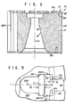
- the rotor 10 is provided with a conical recess 16 ( Figure 2) by which the rotor 10 may be engaged with and driven by a suitable rotor drive arrangement (not shown) in accordance with established principles in the art.
- the body portion 14 of the rotor 10 is provided with a plurality of generally radially outwardly extending arms indicated by reference characters 18A through 18J. Any predetermined number of arms 18 may project radially outwardly from the rotor body 14 consistent with various design considerations. Angularly adjacent ones of the arms 18 cooperate to form a plurality of peripheral grooves 22 disposed about the circumference of the rotor body 12 corresponding in number to the number of the arms 18.
- the axis 24 of each of the grooves 22 is substantially parallel to the axis of rotation CL of the rotor 10.
- the grooves 22 are each provided with a head space 26 ( Figures 1 and 3) which projects radially inwardly into the body 14 of the rotor 10 for purposes described hereinafter. Although shown as semicircular in the Figures it is to be understood that the head space 26 may take any convenient form.
- Each lateral face of each of the arms 18 is provided with a slot 28 which communicates with the adjacent groove 22.
- the slots 28A-1 and 28A-2 ( Figure 1) respectively provided on opposite faces of the arm 18A communicate with the grooves 22A and 22B, respectively.
- the axis of each slot 28 extends substantially parallel to the axis of rotation CL of the rotor 10.
- Each slot 28 has a substantially radially extending base portion 30 ( Figure 3) bounded by radially inner and radially outer wall portions 32 and 34, respectively.
- Each of the slots 28 has a prodetermined width dimension D s measured predetermined radial direction D S mensured in a substantially radial direction with respect to the rotor 10 between the inner and outer walls 32 and 34.
- each groove 22 is partially or fully closed, as by an annular plate 40 or the like suitably secured, as by screws, to the bottom of the rotor body 14.
- the plate 40 is omitted from Figure 1 for purposes of clarity.
- the retaining arrangement 12 in the preferred embodiment takes the form of a retaining lip 42 projecting upwardly from the radially outermost peripheral portions of the arms 18 of the rotor body 14.
- a portion 42L of the retaining lip 42 extends radially inwardly from the periphery of the rotor body 14.
- the portion 42L of each of the retaining lips 42 overlies the upper end, or mouth, of each of the slots 28 machined into the arms 18.
- the portions 42L of the retaining lips 42 overlie the outer radial portion of the slot 28 with which it is associated by a predetermined radial distance D L ( Figure 3).
- each of the retaining lips 42 overlies the radially outer portion of each slot 28 are preferably equal. They may, of course, vary so long as the structural relationship between the slots 28 and the overhang distance of the lips 42 to be described herein is met.
- the undersurface of each of the lips 42 is formed such that a portion thereof lies substantially parallel to the upper surface 14U of the rotor body 14. Alternatively, the undersurface of the lip 42 may be undercut in any manner so long as a portion of the lip effectively overlays a portion of the slot 28.
- the base 30 of each of the slots 28 does not extend in an exactly radial direction of the rotor 10.
- radial distance D s denotes the distance measured in a radial direction with respect to the rotor 10 that lies between the radially inner circumferential wall 32 of the slot 28 and the radially outer circumferential wall 34 thereof.
- each tube carrier C is an elongated member having a predetermined thickness dimension D C (measurable in a substantially radial direction of the rotor) associated therewith.
- the tube carrier C has provided therein a predetermined number of apertures A each adapted to receive and to support individual ones of the tubes T.
- Loaded carriers C are insertable into angularly confronting pairs of the slots 28 formed on angularly confronting lateral faces of the arms 18 which cooperate to define a groove 22.
- the slots 28A-1 and 28J-2 are adapted to receive a tube carrier C in the groove 22A.
- the carriers C are inserted in a direction substantially parallel to the axis CL of the rotor.
- the circumferential clearance distance 48 between the lateral edges of angularly adjacent lips 42 is sufficient to accept the projecting portions of the tubes T carried in the carrier C as the carrier is inserted into the rotor 10.
- the lower end of the tube carrier C is supported against the bottom plate 40 while the opposite lateral edges of the tube carrier C are edgewise confined by each of the respective slots 28 which communicate with the grooves which receives the carrier.
- the heads of the tubes T projecting from the tube carrier C are accommodated in the headspaces 26 formed in the rotor.
- the tube carrier C may have alternate configurations adapted to support tuhes received therein over greater or lesser portions of their length than is afforded by the carrier heretofore discussed. However, such carriers will, in all events, have flanged portions which are insertable into the cooperating confronting slots 28. It should be understood, therefore, that the dimension D C hereinabove used to denote the thickness of the carrier C shown in Figure 3 will, in the appropriate case, also apply to the thickness dimension (measurable in a substantially radial direction of the rotor) of those portions of the carrier C which are inserted into and received and supported by the slots 28.
- the radial dimension D S of each slot 28 is greater than the sum of (1) the radial distance D L that the lip 46 associated with the slot 28 overlies that slot plus (2) the radial thickness dimension D c of the tube carrier C which is edgewise supported in that slot 28.
- the slots 28 are arranged such that a tube carrier C receivable therein is movable within the cooperating slots in response to a centrifugal force from a first, radially inner, position ( Figure 4) to a second, radially outer, position ( Figure 5).
- a centrifugal force When subjected to a centrifugal force the radial outer surface of the tube carrier C moves in the direction of arrow 50 into abutting contact with the radially outer wall 34 of the slots 28 in which the carrier is edgewise supported. In such a position, the carrier C lies beneath the retaining lip 42L portion overhanging the mouth of each slot.
- the undersurface of the lip portion 42L of the retaining member 42 is thus presented as an abutment or barrier to prohibit motion of the tube carrier C in the slots in a direction.parallel to the axis CL of the rotor. Thus, the tube carrier C is effectively prohibited from exiting the slot.
Landscapes
- Centrifugal Separators (AREA)
Applications Claiming Priority (2)
| Application Number | Priority Date | Filing Date | Title |
|---|---|---|---|
| US06/530,653 US4571238A (en) | 1983-09-09 | 1983-09-09 | Centrifuge rotor having a retaining arrangement thereon |
| US530653 | 1983-09-09 |
Publications (2)
| Publication Number | Publication Date |
|---|---|
| EP0137293A2 true EP0137293A2 (de) | 1985-04-17 |
| EP0137293A3 EP0137293A3 (de) | 1985-12-04 |
Family
ID=24114447
Family Applications (1)
| Application Number | Title | Priority Date | Filing Date |
|---|---|---|---|
| EP84110424A Withdrawn EP0137293A3 (de) | 1983-09-09 | 1984-09-01 | Zentrifugenrotor mit Rückhaltevorrichtung |
Country Status (6)
| Country | Link |
|---|---|
| US (1) | US4571238A (de) |
| EP (1) | EP0137293A3 (de) |
| JP (1) | JPS6071056A (de) |
| CA (1) | CA1234789A (de) |
| DK (1) | DK429684A (de) |
| GR (1) | GR80307B (de) |
Cited By (1)
| Publication number | Priority date | Publication date | Assignee | Title |
|---|---|---|---|---|
| GB2617842A (en) * | 2022-04-20 | 2023-10-25 | Entia Ltd | Apparatus for centrifuging |
Families Citing this family (1)
| Publication number | Priority date | Publication date | Assignee | Title |
|---|---|---|---|---|
| US6770244B2 (en) * | 2001-05-03 | 2004-08-03 | Hitachi Chemical Diagnostic, Inc. | Dianostic sample tube including anti-rotation apparatus |
Family Cites Families (6)
| Publication number | Priority date | Publication date | Assignee | Title |
|---|---|---|---|---|
| NL252802A (de) * | 1959-11-20 | |||
| US3891140A (en) * | 1974-02-27 | 1975-06-24 | Becton Dickinson Co | Centrifuge |
| US4341342A (en) * | 1980-12-04 | 1982-07-27 | Kabushiki Kaisha Kubota Seisakusho | Centrifuge |
| US4391597A (en) * | 1981-06-29 | 1983-07-05 | Beckman Instruments, Inc. | Hanger for centrifuge buckets |
| US4375272A (en) * | 1981-07-01 | 1983-03-01 | Beckman Instruments, Inc. | Fixed angle tube carrier |
| DE3141261A1 (de) * | 1981-10-17 | 1983-05-05 | Stuart 07110 Nutley N.J. Beckman | "magnetisch angetriebene zentrifuge" |
-
1983
- 1983-09-09 US US06/530,653 patent/US4571238A/en not_active Expired - Lifetime
-
1984
- 1984-09-01 EP EP84110424A patent/EP0137293A3/de not_active Withdrawn
- 1984-09-06 CA CA000462605A patent/CA1234789A/en not_active Expired
- 1984-09-06 GR GR80307A patent/GR80307B/el unknown
- 1984-09-07 JP JP59186624A patent/JPS6071056A/ja active Pending
- 1984-09-07 DK DK429684A patent/DK429684A/da not_active Application Discontinuation
Cited By (1)
| Publication number | Priority date | Publication date | Assignee | Title |
|---|---|---|---|---|
| GB2617842A (en) * | 2022-04-20 | 2023-10-25 | Entia Ltd | Apparatus for centrifuging |
Also Published As
| Publication number | Publication date |
|---|---|
| GR80307B (en) | 1985-01-08 |
| JPS6071056A (ja) | 1985-04-22 |
| EP0137293A3 (de) | 1985-12-04 |
| CA1234789A (en) | 1988-04-05 |
| DK429684D0 (da) | 1984-09-07 |
| US4571238A (en) | 1986-02-18 |
| DK429684A (da) | 1985-03-10 |
Similar Documents
| Publication | Publication Date | Title |
|---|---|---|
| US10434522B2 (en) | Fixed angle centrifuge rotor having torque transfer members and annular containment groove | |
| EP0208485B1 (de) | Zentrifugalseparator | |
| US4676673A (en) | Bearing disk construction for supporting a spinning rotor shaft of an open-end spinning machine | |
| US4832679A (en) | Rotor for centrifuge | |
| US4571238A (en) | Centrifuge rotor having a retaining arrangement thereon | |
| US4387992A (en) | Rotatable cuvette array | |
| EP0070085B1 (de) | Geschmierte Lager | |
| US2725190A (en) | Cream separator disk assembly | |
| US6213717B1 (en) | Balancing ring for a ceiling fan | |
| EP0626205A2 (de) | Schalenförmiger Zentrifugenrotor | |
| US4102490A (en) | Data ring for vertical tube rotor | |
| US5484381A (en) | Centrifuge rotor having liquid-capturing holes | |
| EP1384512B1 (de) | Rotor für einen Zentrifugalseparator und Adapter dafür | |
| EP0087913B1 (de) | Bandkassette | |
| US5728038A (en) | Centrifuge rotor having structural stress relief | |
| US20230294112A1 (en) | Rotor with improved spill control | |
| EP0832692A3 (de) | Zentrifugenrotor mit reduzierter Massenträgheit | |
| US5538492A (en) | Centrifuge bowl having a line of weakness therein | |
| EP1738360B1 (de) | Vorrichtung zum zentrieren eines informationsmediums auf einem teller | |
| US5295943A (en) | Adapter for holding a pair of centrifuge tubes | |
| EP0562010A1 (de) | Zentrifugenkolben mit geneigtem hals | |
| JPH04505125A (ja) | 遠心分離機 | |
| JPH0754846A (ja) | 高速回転軸装置 | |
| CN1115455A (zh) | 唱盘压紧装置 | |
| EP0199696A3 (de) | Laborzentrifuge |
Legal Events
| Date | Code | Title | Description |
|---|---|---|---|
| PUAI | Public reference made under article 153(3) epc to a published international application that has entered the european phase |
Free format text: ORIGINAL CODE: 0009012 |
|
| AK | Designated contracting states |
Designated state(s): BE DE FR GB IT LU NL |
|
| PUAL | Search report despatched |
Free format text: ORIGINAL CODE: 0009013 |
|
| AK | Designated contracting states |
Designated state(s): BE DE FR GB IT LU NL |
|
| 17P | Request for examination filed |
Effective date: 19851107 |
|
| 17Q | First examination report despatched |
Effective date: 19860829 |
|
| STAA | Information on the status of an ep patent application or granted ep patent |
Free format text: STATUS: THE APPLICATION IS DEEMED TO BE WITHDRAWN |
|
| 18D | Application deemed to be withdrawn |
Effective date: 19870108 |
|
| RIN1 | Information on inventor provided before grant (corrected) |
Inventor name: POTTER, RAYMOND GARY |