EP0137255A2 - Portable steam iron - Google Patents
Portable steam iron Download PDFInfo
- Publication number
- EP0137255A2 EP0137255A2 EP84110021A EP84110021A EP0137255A2 EP 0137255 A2 EP0137255 A2 EP 0137255A2 EP 84110021 A EP84110021 A EP 84110021A EP 84110021 A EP84110021 A EP 84110021A EP 0137255 A2 EP0137255 A2 EP 0137255A2
- Authority
- EP
- European Patent Office
- Prior art keywords
- iron
- housing
- passage
- heating
- steam
- Prior art date
- Legal status (The legal status is an assumption and is not a legal conclusion. Google has not performed a legal analysis and makes no representation as to the accuracy of the status listed.)
- Withdrawn
Links
Images
Classifications
-
- D—TEXTILES; PAPER
- D06—TREATMENT OF TEXTILES OR THE LIKE; LAUNDERING; FLEXIBLE MATERIALS NOT OTHERWISE PROVIDED FOR
- D06F—LAUNDERING, DRYING, IRONING, PRESSING OR FOLDING TEXTILE ARTICLES
- D06F75/00—Hand irons
- D06F75/34—Handles; Handle mountings
-
- D—TEXTILES; PAPER
- D06—TREATMENT OF TEXTILES OR THE LIKE; LAUNDERING; FLEXIBLE MATERIALS NOT OTHERWISE PROVIDED FOR
- D06F—LAUNDERING, DRYING, IRONING, PRESSING OR FOLDING TEXTILE ARTICLES
- D06F75/00—Hand irons
- D06F75/08—Hand irons internally heated by electricity
- D06F75/10—Hand irons internally heated by electricity with means for supplying steam to the article being ironed
- D06F75/14—Hand irons internally heated by electricity with means for supplying steam to the article being ironed the steam being produced from water in a reservoir carried by the iron
- D06F75/18—Hand irons internally heated by electricity with means for supplying steam to the article being ironed the steam being produced from water in a reservoir carried by the iron the water being fed slowly, e.g. drop by drop, from the reservoir to a steam generator
-
- D—TEXTILES; PAPER
- D06—TREATMENT OF TEXTILES OR THE LIKE; LAUNDERING; FLEXIBLE MATERIALS NOT OTHERWISE PROVIDED FOR
- D06F—LAUNDERING, DRYING, IRONING, PRESSING OR FOLDING TEXTILE ARTICLES
- D06F75/00—Hand irons
- D06F75/08—Hand irons internally heated by electricity
- D06F75/24—Arrangements of the heating means within the iron; Arrangements for distributing, conducting or storing the heat
Definitions
- the invention relates to steam irons, and more particularly, to the steam generating and ironing surfache heating means of a steam iron of the compact, portable, snap-together type.
- Portable irons are in use, where the separate handle locks on to the base during use, and where the handle wraps around the base to provide a flat, compact assembly for storage.
- a thin heating element such as a semiconductor having a positive resistance temperature coefficient or a positive temperature coefficient thermistor
- these heating elements in theory can generate heat in the ironing temperature range, such as between 200°C and 240°C, they have not worked satisfactorily in practice.
- These heating elements have only been able to provide heat to the bottom plate or ironing surface in the temperature range of between 140°C and 170°C. This poor performance has been due to the dissipation of the heat to other adjacent surfaces and to poor heating element contact with the bottom plate resulting in uneven and insufficient heating of this ironing surface.
- the problem to be solved by the present invention is to provide an improved portable iron, wherein the ironing surface of the iron is adequately heated, and wherein steam is generated for ironing.
- the housing of the iron of the present invention was redesigned to contain water.
- This redesign had the original purpose of redistributing the generated heat via the water, to bring the bottom plate of the iron up to the ironing temperature of approximately 200°C.
- this redesign also generated steam, which as is commonly known, is a desirable commodity for eliminating wrinkles, i. e. it assists the ironing process.
- the invention features a steam generating iron having a compact heating source.
- a serpentine-like fluid passage is provided within the hollow housing of the iron adjacent the heating element. This serpentine-like passage provides for a greater volume water heating area that efficiently absorbs heat from the heating element and quickly conveys the heat to the water for generating steam.
- the bottom ironing surface has a steam vent for the generated steam.
- a source of water is carried by the housing and is in fluid communication with the passage.
- a heating element is disposed within the housing and is operatively adjacent the serpentine-like passage for heating water in the housing for generating steam.
- the serpentine-like passage provides an extended heating surface whereby the heating element can efficiently generate enough steam to heat the bottom ironing surface to provide a sufficient ironing temperature.
- a portable steam iron having a compact heating element and an extended water heating area is provided, wherein a flat, thin heating element for the iron is used.
- the steam-iron of this invention has a main body 1 and a separable and attachable handle 2.
- the main iron body 1 is hollow.
- the main body 1 houses a heat generating means 30 which is mounted at the bottom surface 3 of the iron.
- Steam vent openings 27 are provided in the bottom surface 3 of the iron at the front tip of the iron and of the below described steam passage 22.
- a base part peripheral cover 4 extends around the base and a temperature insulator plate 5 covers over the top of the components of body 1.
- a steam generating region which includes a serpentine steam passage 22 formed at the upper side of the bottom surface 3 at the front edge of the body 1. That passage is defined on the bottom plate. There are upstanding partitions 29 on the bottom plate in the passage 22 to make it an elongate pathway. The bottom surface 3 of the iron has a steam vent 39 which coincides with the internal opening 27 through the bottom plate of the passage 22.
- the entrance side of the steam passage 22, which is at the rear of the passage and which receives dripping water is positioned along the front side of the below .described heat generating means 30, whereby that entrance side of the passageway 22 can be easily heated.
- the surface area of the passageway 22, to which water is exposed for heating it, is made larger by providing a large number of small protrusions 28 on the bottom plate of the passage.
- Heat generating means 30 is disposed in chamber 23 formed on the bottom surface 3 of the iron adjacent the rear side of the steam passage 22.
- the heat generating means 30. in the chamber 23 includes a plate 33 that is, for example, either in the form of a plate of a semiconductor having a positive resistance temperature coefficient or in the form of a positive temperature coefficient thermistor.
- a pair of electrode plates 32a and 32b respectively contact the opposite top and bottom surfaces of the center plate 33.
- Respective heat conductive plates 31 and 35 contact the outer , sides of the electrode plates 32a and 32b.
- the plate 33 and surrounding plates 32a and 32b are disposed in a supporting insulating frame 34, which includes notches for the projecting terminals on the plates 32.
- the thickness of the heat generating means 30 including the insulating plates 31 and 35 is made the same as the depth of the chamber 23. This is accomplished without any gap between the bottom surface 3 of the iron and the heat covering 21.
- the heat generating means 30 is enclosed within a heat conductive covering 21, which is integrated with-the steam passage 22.
- the lower surface of the heat conductive covering 21 contacts the upper side of the bottom surface 3 of the iron, whereby the latter is heated by that contact.
- the heat generating means 30 is attached to iron base 3, as shown in Fig. 7, by inserting tapered studs 3a and 3b into the openings 24a and 24b in respective flanges projecting from the ends of the covering 21.
- the openings extend to the covering 21 over the heat generating means 30.
- the studs are fixed to the plate by screws 38 and 38.
- Water is supplied in drip fashion to the serpentine steam passage 22 from a detachable cylindrical water container 14 which is nested in a depression 11 defined in the top of the housing cover 5.
- a feed orifice 15 from the water container 14 meters the water supply. Orifice 15 fits into the opening 16 which is provided on the upper surface of the housing cover 5.
- the orifice 15 is made to drip water in a fixed quantity into the steam passage 22 through this collar 41.
- the water enters the steam passage through the supply opening 40.
- the water is converted to steam at high thermal efficiency because the passage 22 has a long meandering route.
- Fig. 9 shows heat generating means 30, represented schematically by its plate 33, and a thermo-switch 6 connected in series.
- the thermo-switch 6 has a housing 58 which supports the ends of a pair of bendable terminal plates 53 and 54 in proximity. These plates make contact via their respective opposed contacts 53a and 54a.
- the housing also supports a bendable bimetallic strip 56.
- At the tip of the bimetallic strip 56 there is an insulating protrusion 57 which passes through a hole 45 in plate 54 to engage plate 53.
- the bendable terminal plate 53 is moved out of electrical contact with terminal plate 54 by the bimetallic strip 56 when the heat generating means 30 heats the strip 56 to a selected operating temperature.
- an insulating tip 52 of an adjustment screw 51 which is screw threadedly advanced through the housing 58.
- Screw 51 is connected to the temperature adjustment knob 6a shown in Figs. 1-3.
- the adjustment knob 6a is turned to a select temperature setting (as shown in Fig. 1), which causes screw 51 to force the tip 52 to bend the plate 54 to a selected extent, which selects the temperature at which the bimetallic strip 56 will cause the plates 53, 54 to come into electric contact.
- the temperature adjusting knob 6a serves the role of an ON and OFF switch for the electric source.
- the insulating tip 52 is advanced the furthest into the housing, and the terminal contacts 53a and 54a are separated. This opens the circuit containing electric source 42. The deflection of the cooled bimetal piece 56 will still not bend the terminal plate 53 enough to restore the circuit to a closed position when knob 6a is turned to OFF.
- the temperature adjustment knob 6a has four rotary setting positions for selecting OFF and ON at low temperature, medium temperature and high temperature.
- the rotation of the screw threaded shaft of the knob moves the insulating tip 52.
- both contact elements 53a and 54a are made to separate in advancing degrees according to the temperature setting.
- both terminal contacts 53a and 54a are not separated by the bimetal piece 56 until that piece has been severely bent by the temperature of the iron.
- a plurality of heater plates 33a, 33b and 33c, respectively, which generate different amounts of heat are selectively used for adjusting the heat generation, instead of using the aforementioned thermo-switch 6.
- These three plates are connected in parallel with the electric source 42.
- the side terminal elements 50c, 50b and 50a which corresponds to the respective heater plates 33c, 33b and 33a, connect to the electric source 42 through contact means 6b.
- the temperature adjusting knob 6a (not shown in Fig. 10) is rotated to the low temperature position, this moves the contact 6b so that electric contact is made with the heater plate 33c which generates a low volume of heat.
- the handle 2 also serves as a case for the main ironing body 1. It has an open side 2a for the insertion of the main ironing body 1. The open area 2b is filled by the iron body 1.
- the bottom 2c of the handle 2 is engaged with the groove 10, which is provided on the upper surface of the insulator plate 5. The engagement of this handle 2 to the plate 5 occurs through the front notch 19 at the tip of the handle 2 engaging at the tip of the lip of 10b of the groove 10, and through the U-shaped ridges 18 engaging the engagement lips 10a on both sides of the rear edge.
- the rear edge of the groove 10a is open. As the handle 2 is moved either inward or outward from the main iron body 1, its bottom part 2c cohtacts the upper surface of the groove 10. Thus, the engagement or disengagement between the handle 2 and the main ironing body 1 is accomplished.
- abutment 12 limits the rearward travel of the installed handle 2.
- Abutment 12 is biased by a spring (not shown) to protrude above the groove 10 and, at the time when it is desired to detach handle 2 from body 1, abutment 12 is pushed down against its spring by the operator's finger to ease handle removal.
- the front tip of the iron body 1 is inserted into the handle 2.
- Surface 8 on the side of the iron body is a guide for this insertion, and ridge 18 contains groove 18c as a stop for the engagement of the main ironing body 1.
- Handle 2 serves the additional purpose of locking the knob 6a in an "OFF" position when the iron is not in use.
- the temperature adjusting knob 6a has a part of its peripheral surface 7 undercut. The portion above the undercut overhangs body 5 when knob 6a is set at the rotary position of "OFF".
- the ridge portion 18a of handle 2 fits in the undercut of knob 6a when the ironing body 1 has been inserted. While the iron body 1 is in the handle 2, the ridge portion 18a makes it impossible to rotate the knob 6a, and particularly to rotate that knob to the "ON" position. When the iron body 1 is to receive the handle 2, it becomes impossible to insert the handle unless the adjusting knob 6a is in the "OFF” position. This is a power safety feature.
- a reel for cord 13 is defined by the undercut portion 9 at the back of iron base 3.
- the heat generating means 30 used in this invention is less complex than the conventional nichrome heating wire, and it enables design of a steam iron of thin construction. Furthermore, there is little danger of the development of conventionally experienced trouble, such as wire mutilation.
- the heat generating means 30 is accommodated in a chamber 23, heat from both the lower and the upper plate surfaces is utilized to heat the iron base 3. This is accomplished by the heat conductive covering 21 that helps heat water to steam in adjacent passage 22.
- the bottom of one of the irons according to the invention was heated to a temperature in the range of between 200 and 210 degrees Centigrade.
- the consumed power ranged between 70 and 150 Watts (70 Watts at the time when steam was not used, and 150 Watts at the time when steam was usied) at 120 volts.
- the aforementioned heat conductive covering 21 has the serpentine steam passage 22 adjacent to it.
- the area of contact with the bottom surface 3 of the iron becomes large, so that it becomes possible to effectively consume the heat generated by the heat generating means 30.
- the iron By generating steam, the iron not only utilizes almost all the available heat being generated, but also provides a better ironing device.
Landscapes
- Engineering & Computer Science (AREA)
- Textile Engineering (AREA)
- Irons (AREA)
- Thermistors And Varistors (AREA)
Abstract
This invention is a feature of a portable steam iron of the compact, portable, snaptogether type. A new heating system comprises a flat semiconductor heating element (30) in heating contact with an adjacent fluid passage (22). The passage (22) provides an extended heating surface wherein the fluid in the passage (22) is converted to steam. The passage (22) extends the heating space by having a serpentine path. The steam that is generated heats the lower base plate (3) to an ironing temperature.
Description
- The invention relates to steam irons, and more particularly, to the steam generating and ironing surfache heating means of a steam iron of the compact, portable, snap-together type.
- Portable irons are in use, where the separate handle locks on to the base during use, and where the handle wraps around the base to provide a flat, compact assembly for storage.
- To provide a more compact iron body, a thin heating element, such as a semiconductor having a positive resistance temperature coefficient or a positive temperature coefficient thermistor, has been used. While these heating elements in theory can generate heat in the ironing temperature range, such as between 200°C and 240°C, they have not worked satisfactorily in practice. These heating elements have only been able to provide heat to the bottom plate or ironing surface in the temperature range of between 140°C and 170°C. This poor performance has been due to the dissipation of the heat to other adjacent surfaces and to poor heating element contact with the bottom plate resulting in uneven and insufficient heating of this ironing surface.
- The above-mentioned problem was not solved by merely increasing the heat generating capacity of the heating element. Increasing this heat generating capacity has sometimes caused the iron to become overly hot, with the danger of possibly burning other parts of the iron.
- The problem to be solved by the present invention is to provide an improved portable iron, wherein the ironing surface of the iron is adequately heated, and wherein steam is generated for ironing.
- This problem is solved by the features of the characterizing clause of claim 1.
- Further developements and advantageous features are set out in the subclaims.
- The housing of the iron of the present invention was redesigned to contain water. This redesign had the original purpose of redistributing the generated heat via the water, to bring the bottom plate of the iron up to the ironing temperature of approximately 200°C. However, this redesign also generated steam, which as is commonly known, is a desirable commodity for eliminating wrinkles, i. e. it assists the ironing process.
- The invention features a steam generating iron having a compact heating source. In order to maximize steam generation, a serpentine-like fluid passage is provided within the hollow housing of the iron adjacent the heating element. This serpentine-like passage provides for a greater volume water heating area that efficiently absorbs heat from the heating element and quickly conveys the heat to the water for generating steam. The bottom ironing surface has a steam vent for the generated steam. A source of water is carried by the housing and is in fluid communication with the passage.
- A heating element is disposed within the housing and is operatively adjacent the serpentine-like passage for heating water in the housing for generating steam. The serpentine-like passage provides an extended heating surface whereby the heating element can efficiently generate enough steam to heat the bottom ironing surface to provide a sufficient ironing temperature.
- In accordance with the invention, a portable steam iron having a compact heating element and an extended water heating area is provided, wherein a flat, thin heating element for the iron is used.
- The foregoing and other features of the invention will be apparent from the following description considered in conjunction with the accompanying drawings, wherein:
- Fig. 1 is an exploded perspective view of a steam iron according to this invention;
- Fig. 2 is a plan view of the iron;
- Fig. 3 is a side view of the iron;
- Fig. 4 is a bottom view of the iron;
- Fig. 5 is a cross-sectional view taken along line 5-5 of Fig. 2;
- Fig. 6 is a fragmentary cross-sectional view taken along line 6-6 of Fig. 2;
- Fig. 7 is a side cross-sectional view of the bottom of the iron;
- Fig. 8 is an exploded perspective view of a heat generating element and fluid passage which is used in the iron;
- Fig. 9 is a schematic diagram showing circuitry in the iron; and
- Fig. 10 schematically shows the circuit in an alternate embodiment.
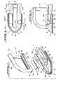
- Referring to Fig. 1, the steam-iron of this invention has a main body 1 and a separable and
attachable handle 2. The main iron body 1 is hollow. Referring to Figs. 7 and 8, the main body 1 houses a heat generating means 30 which is mounted at thebottom surface 3 of the iron.Steam vent openings 27 are provided in thebottom surface 3 of the iron at the front tip of the iron and of the below describedsteam passage 22. A base partperipheral cover 4 extends around the base and atemperature insulator plate 5 covers over the top of the components of body 1. - As shown in Figs. 7 and 8, there is a steam generating region which includes a
serpentine steam passage 22 formed at the upper side of thebottom surface 3 at the front edge of the body 1. That passage is defined on the bottom plate. There areupstanding partitions 29 on the bottom plate in thepassage 22 to make it an elongate pathway. Thebottom surface 3 of the iron has asteam vent 39 which coincides with theinternal opening 27 through the bottom plate of thepassage 22. In addition, the entrance side of thesteam passage 22, which is at the rear of the passage and which receives dripping water, is positioned along the front side of the below .described heat generating means 30, whereby that entrance side of thepassageway 22 can be easily heated. The surface area of thepassageway 22, to which water is exposed for heating it, is made larger by providing a large number ofsmall protrusions 28 on the bottom plate of the passage. - As shown in Fig. 6, over the top of the steam,
pas7 sage 22, there is a cover having a water supply opening 40. The cover prevents leakage of the steam. -
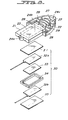
Heat generating means 30 is disposed inchamber 23 formed on thebottom surface 3 of the iron adjacent the rear side of thesteam passage 22. The heat generating means 30. in thechamber 23 includes aplate 33 that is, for example, either in the form of a plate of a semiconductor having a positive resistance temperature coefficient or in the form of a positive temperature coefficient thermistor. A pair ofelectrode plates center plate 33. Respective heatconductive plates electrode plates plate 33 and surroundingplates frame 34, which includes notches for the projecting terminals on the plates 32. - The thickness of the heat generating means 30 including the
insulating plates chamber 23. This is accomplished without any gap between thebottom surface 3 of the iron and the heat covering 21. - There is a peripheral gap between the peripheral portion of heat generating means 30 and its
chamber 23, into which a heat resistant insulator-fixing agent 25. such as silicon rubber, is injected. Theinsulating frame 34 and the insulator-fixing agent 25 prevent short-circuiting betweenelectrode plates - The heat generating means 30 is enclosed within a heat conductive covering 21, which is integrated with-the
steam passage 22. The lower surface of the heat conductive covering 21 contacts the upper side of thebottom surface 3 of the iron, whereby the latter is heated by that contact. - The heat generating means 30 is attached to
iron base 3, as shown in Fig. 7, by insertingtapered studs 3a and 3b into theopenings 24a and 24b in respective flanges projecting from the ends of thecovering 21. The openings extend to the covering 21 over the heat generating means 30. The studs are fixed to the plate byscrews - Water is supplied in drip fashion to the
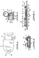
serpentine steam passage 22 from a detachablecylindrical water container 14 which is nested in a depression 11 defined in the top of thehousing cover 5. Afeed orifice 15 from thewater container 14 meters the water supply. Orifice 15 fits into theopening 16 which is provided on the upper surface of thehousing cover 5. In the opening 16, there is a grommet or sealingcollar 41, as shown in Fig. 6. Theorifice 15 is made to drip water in a fixed quantity into thesteam passage 22 through thiscollar 41. The water enters the steam passage through thesupply opening 40. The water is converted to steam at high thermal efficiency because thepassage 22 has a long meandering route. - Fig. 9 shows heat generating means 30, represented schematically by its
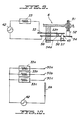
plate 33, and a thermo-switch 6 connected in series. The thermo-switch 6, has ahousing 58 which supports the ends of a pair of bendableterminal plates opposed contacts 53a and 54a. The housing also supports a bendablebimetallic strip 56. At the tip of thebimetallic strip 56, there is an insulatingprotrusion 57 which passes through ahole 45 inplate 54 to engageplate 53. Thebendable terminal plate 53 is moved out of electrical contact withterminal plate 54 by thebimetallic strip 56 when the heat generating means 30 heats thestrip 56 to a selected operating temperature. - At the end of the
terminal element plate 54 is an insulatingtip 52 of anadjustment screw 51 which is screw threadedly advanced through thehousing 58.Screw 51 is connected to thetemperature adjustment knob 6a shown in Figs. 1-3. Theadjustment knob 6a is turned to a select temperature setting (as shown in Fig. 1), which causesscrew 51 to force thetip 52 to bend theplate 54 to a selected extent, which selects the temperature at which thebimetallic strip 56 will cause theplates temperature adjusting knob 6a serves the role of an ON and OFF switch for the electric source. At the OFF setting, the insulatingtip 52 is advanced the furthest into the housing, and theterminal contacts 53a and 54a are separated. This opens the circuit containingelectric source 42. The deflection of the cooledbimetal piece 56 will still not bend theterminal plate 53 enough to restore the circuit to a closed position whenknob 6a is turned to OFF. - The
temperature adjustment knob 6a has four rotary setting positions for selecting OFF and ON at low temperature, medium temperature and high temperature. The rotation of the screw threaded shaft of the knob moves the insulatingtip 52. When thebimetal piece 56 bends at high temperature, bothcontact elements 53a and 54a are made to separate in advancing degrees according to the temperature setting. When thetemperature adjustment knob 6a has been rotated to the highest temperature position, bothterminal contacts 53a and 54a are not separated by thebimetal piece 56 until that piece has been severely bent by the temperature of the iron. - In the alternative embodiment shown in Fig. 10, a plurality of
heater plates 33a, 33b and 33c, respectively, which generate different amounts of heat are selectively used for adjusting the heat generation, instead of using the aforementioned thermo-switch 6. These three plates are connected in parallel with theelectric source 42. Theside terminal elements respective heater plates 33c, 33b and 33a, connect to theelectric source 42 through contact means 6b. When thetemperature adjusting knob 6a (not shown in Fig. 10) is rotated to the low temperature position, this moves thecontact 6b so that electric contact is made with theheater plate 33c which generates a low volume of heat. When the knob .is rotated to the medium temperature position, electric contact is also made bycontact 6b with heater plate 33b to generate a medium volume of heat. When the knob is rotated to the high temperature position, electric contact is additionally made bycontact 6b with the heater plate 33a to generate a high volume of heat. The arrangement can be adapted to enable various ones of the plates 33a, b, c to be electrified. - For example, to effect quick heating, electricity is passed to the heater element 33a to obtain a high volume of heat. When a high temperature is reached , the electric current flows to the
other heater elements 33b and 33c. After the initial stage of electric passage, or at the time when the temperature is low due to the use of steam, the electric current flows to theheater elements 33b and 33c. - The
handle 2 also serves as a case for the main ironing body 1. It has an open side 2a for the insertion of the main ironing body 1. Theopen area 2b is filled by the iron body 1. To assemble the iron, the bottom 2c of thehandle 2 is engaged with thegroove 10, which is provided on the upper surface of theinsulator plate 5. The engagement of thishandle 2 to theplate 5 occurs through thefront notch 19 at the tip of thehandle 2 engaging at the tip of the lip of 10b of thegroove 10, and through theU-shaped ridges 18 engaging the engagement lips 10a on both sides of the rear edge. - The rear edge of the groove 10a is open. As the
handle 2 is moved either inward or outward from the main iron body 1, itsbottom part 2c cohtacts the upper surface of thegroove 10. Thus, the engagement or disengagement between thehandle 2 and the main ironing body 1 is accomplished. - In addition,
abutment 12 limits the rearward travel of the installedhandle 2.Abutment 12 is biased by a spring (not shown) to protrude above thegroove 10 and, at the time when it is desired to detachhandle 2 from body 1,abutment 12 is pushed down against its spring by the operator's finger to ease handle removal. - At the time when the iron is not in use and the handle is separate from the iron, the front tip of the iron body 1 is inserted into the
handle 2.Surface 8 on the side of the iron body is a guide for this insertion, andridge 18 containsgroove 18c as a stop for the engagement of the main ironing body 1. -
Handle 2 serves the additional purpose of locking theknob 6a in an "OFF" position when the iron is not in use. Thetemperature adjusting knob 6a has a part of itsperipheral surface 7 undercut. The portion above the undercut overhangsbody 5 whenknob 6a is set at the rotary position of "OFF". The ridge portion 18a ofhandle 2 fits in the undercut ofknob 6a when the ironing body 1 has been inserted. While the iron body 1 is in thehandle 2, the ridge portion 18a makes it impossible to rotate theknob 6a, and particularly to rotate that knob to the "ON" position. When the iron body 1 is to receive thehandle 2, it becomes impossible to insert the handle unless the adjustingknob 6a is in the "OFF" position. This is a power safety feature. - A reel for
cord 13 is defined by the undercutportion 9 at the back ofiron base 3. - The heat generating means 30 used in this invention is less complex than the conventional nichrome heating wire, and it enables design of a steam iron of thin construction. Furthermore, there is little danger of the development of conventionally experienced trouble, such as wire mutilation.
- Since, the heat generating means 30 is accommodated in a
chamber 23, heat from both the lower and the upper plate surfaces is utilized to heat theiron base 3. This is accomplished by the heat conductive covering 21 that helps heat water to steam inadjacent passage 22. - In an actual test, the bottom of one of the irons according to the invention was heated to a temperature in the range of between 200 and 210 degrees Centigrade. The consumed power ranged between 70 and 150 Watts (70 Watts at the time when steam was not used, and 150 Watts at the time when steam was usied) at 120 volts.
- The aforementioned heat conductive covering 21 has the
serpentine steam passage 22 adjacent to it. As a result, the area of contact with thebottom surface 3 of the iron becomes large, so that it becomes possible to effectively consume the heat generated by the heat generating means 30. By generating steam, the iron not only utilizes almost all the available heat being generated, but also provides a better ironing device. - Although the present invention has been described in connection with preferred embodiments thereof, many variations and modifications will now become apparent to those skilled in the art. It is preferred, therefore, that the present invention be limited not by the specific disclosure herein, but only by the appended claims.
Claims (17)
1. A portable steam iron, comprising:
- a hollow housing (1), an ironing base (3) beneath the housing (1), a steam vent (39) in the base (3) for outlet of steam from the housing (1),
- a water inlet (16) to the housing (1) and a water supply (14) in communication with the inlet to the hollow of the housing for delivery of water to the housing (1), characterized by
- a generally serpentine passage (22), defined in and through the hollow of the housing (1) and placed and shaped for transmitting water from the vicinity of the inlet (16) toward the steam vent (39) and for transmitting steam to the steam vent (39); and
- heating means (30) in the hollow of the housing (1) and placed for heating water in the passage (22) for generating steam in the passage (22) from water in the passage (22), and the passage (22) having elements (29, 21) therein for defining a heating surface for water and also for heating the base to an iron temperature.
2. The iron of claim 1, characterized by a metering orifice (15) defined in the inlet (16) for metering a supply of water to the passage (22).
3. The iron of claim 1, characterized in that the heating means (30) is adjustable for establishing different levels of heating of the base (3) of the iron.
4. The iron of claim 3, characterized by a selector knob (6a) on the housing (1) and operatively connected to the heating means (30) for selecting a heat setting for the heating means.
5. The iron of claim 4, characterized by a handle (2) detachably attachable to the housing (1) for supporting the housing in use; the handle (2) also having a storage position around the periphery of the housing (1) and around the periphery of the base (3), the selector knob (6a) being shaped and positioned to interfere with the emplacement and removal of the handle (2) into the storage position; the knob having a cut away portion which provides clearance for the handle (2) to be moved past the knob (6a) to the storage position; the cut away portion being placed on the knob so that when the knob (6a) is rotated to the position for the heating means to be off, the cut away portion is placed to permit the handle (2) to be moved past the knob (6a) and through the cut away portion to the storage position.
6. The iron of claim 1, characterized by a handle (2) for the housing (1).
7. The iron of claim 6, characterized in that the handle (2) is detachably attachable to the housing (1).
8. The iron of claim 7, characterized in that the handle (2) also has a storage position around the periphery of the housing (1) and the periphery of the base (3).
9. The iron of claim 1, characterized in that the heating means(30) comprises a plate-like unit disposed to the rear of the passage (22) of the housing (1), and the steam vent (39) being toward the front of the housing (1) and away from the plate-like unit along the passage (22).
10. The iron of claim 9, characterized in that the heating means (30) comprises a plate-like heating plate means (33) for being electrically heated and connectable with a source of electricity for electrical heating of the heating means (30).
11. The iron of claim 10, characterized in that the heating means (30) comprises a top plate (31) above and a bottom plate (35) below the heating plate means (33) for protecting the heating plate means (33) and also for transmitting heat therefrom, including heat transmission to the base (3) and including heat transmission from the top plate (31) for providing heat to the passage (22) and to the water in the passage (22) for generating steam.
12. The iron of claim 11, characterized in that the heating plate means (33) includes an electrically activated plate and comprises a respective electric contact (32a) above and a respective electric contact (32b) below the electrically activated plate (33), the contacts (32a, 32b) being covered by the top and bottom plates (31, 35), respectively.
13. The iron of claim 10, characterized in that the heating plate means (33) comprises a positive temperature coefficient thermistor.
14. The iron of claim 10, characterized in that the heating plate means (33) comprises a semiconductor having a positive temperature resistance coefficient.
15. The iron of any of the preceding claims, characterized in that the water supply comprises a container (14) on top of the housing.
16. The iron of any of the preceding claims, characterized in that the passage (22) is defined by partitions (29) in the housing (1) and supported upstanding in the housing above the base (3).
17. The iron of claim 16, characterized by a plurality of protrusions (28) above the base (3) and in the passage (22) for assisting in the heating of water in the passage (22) for generating steam.
Applications Claiming Priority (2)
| Application Number | Priority Date | Filing Date | Title |
|---|---|---|---|
| JP137683/83 | 1983-09-05 | ||
| JP1983137683U JPS6044798U (en) | 1983-09-05 | 1983-09-05 | steam iron |
Publications (2)
| Publication Number | Publication Date |
|---|---|
| EP0137255A2 true EP0137255A2 (en) | 1985-04-17 |
| EP0137255A3 EP0137255A3 (en) | 1986-01-08 |
Family
ID=15204365
Family Applications (1)
| Application Number | Title | Priority Date | Filing Date |
|---|---|---|---|
| EP84110021A Withdrawn EP0137255A3 (en) | 1983-09-05 | 1984-08-22 | Portable steam iron |
Country Status (3)
| Country | Link |
|---|---|
| US (1) | US4716276A (en) |
| EP (1) | EP0137255A3 (en) |
| JP (1) | JPS6044798U (en) |
Cited By (2)
| Publication number | Priority date | Publication date | Assignee | Title |
|---|---|---|---|---|
| FR2696197A1 (en) * | 1992-09-29 | 1994-04-01 | Seb Sa | Iron with steam chamber equipped with a water distribution grid. |
| US10767305B2 (en) | 2016-05-02 | 2020-09-08 | Koninklijke Philips N.V. | Steam iron with thermal bridge arrangement |
Families Citing this family (10)
| Publication number | Priority date | Publication date | Assignee | Title |
|---|---|---|---|---|
| FR2641291B1 (en) * | 1989-01-04 | 1991-03-22 | Seb Sa | |
| US5115787A (en) * | 1991-09-24 | 1992-05-26 | Texas Instruments Incorporated | Spark ignition combustion engine of the fuel injection type and heating element therefor |
| FR2727439B1 (en) * | 1994-11-25 | 1996-12-27 | Seb Sa | MULTI-ZONE IRON |
| US5922231A (en) * | 1997-05-13 | 1999-07-13 | Dekko Heating Technologies, Inc. | Voltage surge resistant positive temperature coefficient heater |
| DE29816467U1 (en) * | 1998-09-14 | 1998-12-17 | Lin, Chun-liang, Lin Kou Hsiang, Taipeh | Small electric iron |
| CN1965123A (en) * | 2004-06-02 | 2007-05-16 | 皇家飞利浦电子股份有限公司 | Steam generator having at least one spiral-shaped steam channel and at least one flat resistive heating element |
| CN101196288A (en) * | 2006-12-08 | 2008-06-11 | 厦门灿坤实业股份有限公司 | Flat-iron and steam generating device thereof |
| US8893410B2 (en) * | 2010-03-12 | 2014-11-25 | Euro-Pro Operating Llc | Fabric care appliance |
| JP7236661B2 (en) * | 2019-02-27 | 2023-03-10 | パナソニックIpマネジメント株式会社 | steam jets and steam irons |
| WO2022150416A1 (en) * | 2021-01-05 | 2022-07-14 | Romain Pierre | Microwavable material smoothing apparatus |
Family Cites Families (23)
| Publication number | Priority date | Publication date | Assignee | Title |
|---|---|---|---|---|
| US686080A (en) * | 1901-05-16 | 1901-11-05 | Michael Joyce | Sad-iron. |
| US1969583A (en) * | 1933-03-01 | 1934-08-07 | Skolnik Max | Electric ironer and dampener |
| US2350452A (en) * | 1941-12-02 | 1944-06-06 | Westinghouse Electric & Mfg Co | Steam iron |
| US2620576A (en) * | 1946-11-08 | 1952-12-09 | Proctor Electric Co | Steam iron with controlled water flow |
| US2542858A (en) * | 1946-11-15 | 1951-02-20 | Boring Isaac Hartsell | Pressing iron |
| US2802289A (en) * | 1948-03-31 | 1957-08-13 | Gen Electric | Steam iron |
| US2652645A (en) * | 1949-11-05 | 1953-09-22 | Casco Products Corp | Steam flatiron |
| BE510241A (en) * | 1951-03-28 | |||
| FR1072774A (en) * | 1953-06-29 | 1954-09-15 | Iron | |
| US3061958A (en) * | 1959-05-18 | 1962-11-06 | Thurlow G Gregory | Electric steam irons |
| US3245160A (en) * | 1965-07-26 | 1966-04-12 | Knapp Monarch Co | Water reservoir for travel irons and control therefor |
| DD117091A1 (en) * | 1974-11-07 | 1975-12-20 | ||
| DE2608500C3 (en) * | 1976-03-02 | 1979-12-20 | Erich Rudolf Baumgartner | Iron |
| NL7603997A (en) * | 1976-04-15 | 1977-10-18 | Philips Nv | ELECTRICAL HEATING DEVICE CONTAINING A RESISTANCE BODY OF PTC MATERIAL. |
| DE2654781C2 (en) * | 1976-12-03 | 1978-07-27 | Rowenta-Werke Gmbh, 6050 Offenbach | Electric steam iron |
| DE2743880C3 (en) * | 1977-09-29 | 1981-05-14 | Siemens AG, 1000 Berlin und 8000 München | Heating device with an optimized heating element made from PTC thermistor material |
| DE2748792A1 (en) * | 1977-10-31 | 1979-05-03 | Braun Ag | IRON WITH A CONTROL DEVICE FOR THE ENERGY SUPPLY TO THE HEATING CONDUCTOR ARRANGEMENT |
| JPS57142096A (en) * | 1981-02-27 | 1982-09-02 | Citizen Watch Co Ltd | Operating controller for electronic device |
| JPS57143098A (en) * | 1981-02-27 | 1982-09-04 | Tetsuya Takigawa | Back filling method and material of covering segment in shield constructing method |
| JPS57143097A (en) * | 1981-02-27 | 1982-09-04 | Mitsui Shipbuilding Eng | Soil pressure balance type shield drilling machine |
| JPS57143099A (en) * | 1981-02-28 | 1982-09-04 | Gijiyutsu Shigen Kaihatsu Kk | Tunnel lining method |
| JPS57145398A (en) * | 1981-03-03 | 1982-09-08 | Nippon Electric Co | Panel containing structure |
| JPS57145397A (en) * | 1981-03-04 | 1982-09-08 | Hitachi Ltd | Method of producing multilayer printed circuit board |
-
1983
- 1983-09-05 JP JP1983137683U patent/JPS6044798U/en active Granted
-
1984
- 1984-08-22 EP EP84110021A patent/EP0137255A3/en not_active Withdrawn
-
1986
- 1986-07-03 US US06/882,214 patent/US4716276A/en not_active Expired - Fee Related
Cited By (3)
| Publication number | Priority date | Publication date | Assignee | Title |
|---|---|---|---|---|
| FR2696197A1 (en) * | 1992-09-29 | 1994-04-01 | Seb Sa | Iron with steam chamber equipped with a water distribution grid. |
| EP0592334A1 (en) * | 1992-09-29 | 1994-04-13 | Seb S.A. | Steam iron comprising a grid for distributing the water |
| US10767305B2 (en) | 2016-05-02 | 2020-09-08 | Koninklijke Philips N.V. | Steam iron with thermal bridge arrangement |
Also Published As
| Publication number | Publication date |
|---|---|
| JPS6044798U (en) | 1985-03-29 |
| EP0137255A3 (en) | 1986-01-08 |
| US4716276A (en) | 1987-12-29 |
| JPS6117760Y2 (en) | 1986-05-30 |
Similar Documents
| Publication | Publication Date | Title |
|---|---|---|
| EP0137255A2 (en) | Portable steam iron | |
| US3675449A (en) | Steaming apparatus with removable brush | |
| CA2088658C (en) | Heating element for an air flow heater | |
| US4208570A (en) | Thermostatically controlled electric engine coolant heater | |
| US4631387A (en) | Aroma generating apparatus with electrical heating element | |
| US6891133B2 (en) | Cooking apparatus | |
| JP2769529B2 (en) | Contact lens disinfector | |
| US3858029A (en) | Hairsetter | |
| EP0296807A2 (en) | Aroma diffuser assembly | |
| US5896864A (en) | Hair curler steamer with PTC heater and thermally isolated cold and hot water reservoirs | |
| US3534392A (en) | Electrical curling tongs | |
| GR3030502T3 (en) | Electric vaporizer for active substances | |
| US5866878A (en) | Kettle with power connector module | |
| US20040190883A1 (en) | Lock and key system for fragrance heaters | |
| US2880530A (en) | Electric iron | |
| US3621197A (en) | Protector shields for thermostats | |
| US3870858A (en) | Thermostat mounting | |
| US3626151A (en) | Protector shield | |
| US3007028A (en) | Electrically heated device with plug-in thermostat | |
| JP3633329B2 (en) | Instant heating water heater | |
| US20200333044A1 (en) | Instant electrode water heater | |
| US3450860A (en) | Liquid heater with high temperature safety control | |
| US3231717A (en) | Electrically heated vessel and detachable temperature-regulating connector therefor | |
| US2462942A (en) | Electric iron | |
| US4285145A (en) | Thermostat and iron assembly |
Legal Events
| Date | Code | Title | Description |
|---|---|---|---|
| PUAI | Public reference made under article 153(3) epc to a published international application that has entered the european phase |
Free format text: ORIGINAL CODE: 0009012 |
|
| AK | Designated contracting states |
Designated state(s): CH DE FR GB IT LI SE |
|
| PUAL | Search report despatched |
Free format text: ORIGINAL CODE: 0009013 |
|
| AK | Designated contracting states |
Designated state(s): CH DE FR GB IT LI SE |
|
| STAA | Information on the status of an ep patent application or granted ep patent |
Free format text: STATUS: THE APPLICATION HAS BEEN WITHDRAWN |
|
| 18W | Application withdrawn |
Withdrawal date: 19860210 |
|
| RIN1 | Information on inventor provided before grant (corrected) |
Inventor name: MOTEGI, AKIO Inventor name: SAITO, TAKAO |