EP0137080A2 - Universal hinge-type joint - Google Patents
Universal hinge-type joint Download PDFInfo
- Publication number
- EP0137080A2 EP0137080A2 EP83305332A EP83305332A EP0137080A2 EP 0137080 A2 EP0137080 A2 EP 0137080A2 EP 83305332 A EP83305332 A EP 83305332A EP 83305332 A EP83305332 A EP 83305332A EP 0137080 A2 EP0137080 A2 EP 0137080A2
- Authority
- EP
- European Patent Office
- Prior art keywords
- joint
- score lines
- rigid sections
- implement
- score
- Prior art date
- Legal status (The legal status is an assumption and is not a legal conclusion. Google has not performed a legal analysis and makes no representation as to the accuracy of the status listed.)
- Granted
Links
Images

Classifications
-
- B—PERFORMING OPERATIONS; TRANSPORTING
- B29—WORKING OF PLASTICS; WORKING OF SUBSTANCES IN A PLASTIC STATE IN GENERAL
- B29C—SHAPING OR JOINING OF PLASTICS; SHAPING OF MATERIAL IN A PLASTIC STATE, NOT OTHERWISE PROVIDED FOR; AFTER-TREATMENT OF THE SHAPED PRODUCTS, e.g. REPAIRING
- B29C53/00—Shaping by bending, folding, twisting, straightening or flattening; Apparatus therefor
- B29C53/02—Bending or folding
- B29C53/04—Bending or folding of plates or sheets
- B29C53/06—Forming folding lines by pressing or scoring
-
- B—PERFORMING OPERATIONS; TRANSPORTING
- B25—HAND TOOLS; PORTABLE POWER-DRIVEN TOOLS; MANIPULATORS
- B25G—HANDLES FOR HAND IMPLEMENTS
- B25G3/00—Attaching handles to the implements
- B25G3/38—Hinged, pivoted, swivelling, or folding joints
-
- F—MECHANICAL ENGINEERING; LIGHTING; HEATING; WEAPONS; BLASTING
- F16—ENGINEERING ELEMENTS AND UNITS; GENERAL MEASURES FOR PRODUCING AND MAINTAINING EFFECTIVE FUNCTIONING OF MACHINES OR INSTALLATIONS; THERMAL INSULATION IN GENERAL
- F16C—SHAFTS; FLEXIBLE SHAFTS; ELEMENTS OR CRANKSHAFT MECHANISMS; ROTARY BODIES OTHER THAN GEARING ELEMENTS; BEARINGS
- F16C11/00—Pivots; Pivotal connections
- F16C11/04—Pivotal connections
- F16C11/12—Pivotal connections incorporating flexible connections, e.g. leaf springs
-
- B—PERFORMING OPERATIONS; TRANSPORTING
- B29—WORKING OF PLASTICS; WORKING OF SUBSTANCES IN A PLASTIC STATE IN GENERAL
- B29C—SHAPING OR JOINING OF PLASTICS; SHAPING OF MATERIAL IN A PLASTIC STATE, NOT OTHERWISE PROVIDED FOR; AFTER-TREATMENT OF THE SHAPED PRODUCTS, e.g. REPAIRING
- B29C37/00—Component parts, details, accessories or auxiliary operations, not covered by group B29C33/00 or B29C35/00
- B29C37/0053—Moulding articles characterised by the shape of the surface, e.g. ribs, high polish
- B29C37/0057—Moulding single grooves or ribs, e.g. tear lines
Definitions
- the present invention relates to joints.
- it relates to joints that connect implement members allowing movement of one of the implement members in a plurality of planes.
- the Bailey Patent 3,720,976 shows a toilet brush having a ball joint pivotally connecting the handle to the brush.
- a ball joint of course, is an expensive type of joint and is not suitable for application in a wide variety of implements.
- the Johnson et al Patent 3,768,110 shows a swivel mop head having a single continuous serpentine slot disposed through a mid-portion of the body of the mop head.
- the portions of the mop head defined by parallel portions of the serpentine slot are capable of flexing upwardly and downwardly and angularly, providing the mop with the capability of being used in various angular positions.
- this type of joint would be quite difficult to apply to a smaller implement.
- a smaller implement having a joint is shown in the Burns et al Patent 3,369,268.
- a paint applicator includes a handle that is movable in one angular direction with respect to the applicator. Although the handle is movable with respect to the paint applicator, the movement is limited to just one direction.
- a paint roller is disclosed that is rotatably mounted to an axle.
- a handle in turn, is pivotally attached to the axle, permitting pivotal movement in an angular direction within one plane. Again, the movement between the handle and the roller is limited to one direction in a plane.
- the present invention includes a universal hinge-type joint for use in connecting a first and second implement member to each other, such as a sanding tool pad to a handle of a sanding tool.
- the joint includes an integral body having a first end connected to the first implement member and a second end connected to the second implement member.
- a plurality of substantially rigid sections are defined by at least two flexible portions of reduced thickness defining non-parallel axes of rotation. The rigid sections are bendable along the flexible portions in a plurality of planes allowing rotation of the second implement member in a plurality of angular positions with respect to the first implement member.
- the integral body is substantially flat and the flexible portions include first and second score lines which bisect each other in a central portion of the flat body to form an "X" configuration and four rigid sections. Two of the four rigid sections positioned on opposite sides of the "X" configuration include the ends which are fixedly attached to the first and second implement members.
- a third score line is also provided which intersects the first and second score limes.
- the third score line is positioned between the "X" configuration of the second and third score lines and the first end which is fixedly attached to the first implement member such that the flat body is additionally bendable along the third score line.
- the third score line is positioned to bisect the point of intersection of the second and third score lines and to bisect the other two rigid sections that are not attached to the first and second implement members into an additional four rigid sections.
- the universal hinge-type joint of the present invention is illustrated in a preferred use in a sanding tool 12 in Figure l. To more clearly describe the present invention, like reference characters will be used to indicate like elements throughout the figures.
- the sanding tool 12 includes a suitable sanding pad 14 and a handle 16.
- the joint 10 connects the pad 14 to the handle 16.
- the joint 10 includes a preferred substantially flat body 18 and first and second score lines 20, 22, defining flexible portions.
- the score lines, 20, 22 bisect each other in a central portion of the flat body 18, dividing the flat body 18 into four discrete substantially rigid sections 24, 26, 28 and 30.
- the score lines 22, 20 are a reduced thickness and sufficiently deep to allow bending of the flat body 18 along the score lines.
- the substantially rigid sections 24, 26, 28 and 30 provide sufficient support for motive force to be transmitted from the handle 16 to the pad 14.
- a third score line 32 is positioned between the rigid section 26 and the pad 14 defining a connecting section 34 which is fixedly attached to the.pad 14.
- the third score line 32 is also sufficiently deep to allow bending of the flat body 18 along the direction of arrow 36, as illustrated in Figure 2.
- the joint 10 is a unitary joint preferably made of a suitable plastic material, such as polypropylene, that allows repeated bending along the score lines 20, 22 and 32 without breaking.
- the score lines are disposed on both sides of the flat body and are produced by a suitable "scoring" process, or alternatively, are formed simultaneously with the flat body by suitable molding or stamping processes.
- FIGs 3 and 4 The movement of the universal hinge-type joint of the present invention is more fully illustrated in Figures 3 and 4.
- the handle 16 is rotated along its axis in a direction of arrow 38 and along arrow 36, thereby bending the main body along score lines 20 and 32.
- the handle 16 is rotated in a direction of arrow 40 and arrow 36, as illustrated in Figure 4, the main body 18 is bent along score lines 22 and 32.
- the rigid sections 24, 26, 28 and 30 of the main body 18 are bendable along the score lines in a plurality of planes permitting the use of the sanding tool in a wide range of angular positions.
- the rigid sections are rotatable along axes defined by the score lines which are non-parallel to each other and to a major axis defined by the handle 16 and the body 18 when in a non-rotated position.
- the universal hinge-type joint is adaptable for use with a wide variety of implements and not restricted to just sanding tools.
- the alternative embodiment of the universal hinge-type joint is generally indicated at 42.
- the joint 42 similarly has a substantially flat body 44 which is attached at one end to the handle 16 of the sanding tool and to the pad 14 at another end.
- the joint 42 is similarly constructed with first and second score lines 46, 48 bisecting each other in a central portion of the flat body 44.
- a third score line 50 is positioned in the flat body 44 such that the third score line bisects the score lines 46, 48 at their point of intersection 52. Consequently, the score lines 46, 48 and 50 define substantially rigid sections 54, 56, 58, 60, 62 and 64,.
- the rigid section 54 is fixedly attached to the handle 16 and the rigid section 60 is fixedly attached to the pad 14.
- the score lines 46, 48 and 50 are sufficiently deep such that the main body is bendable along the score lines with the rigid sections providing sufficient beam strength to the joint 42 for motive force to be transmitted from the handle 16 to the pad 14 for sanding.
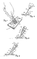
- FIG. 7 The movement of the preferred embodiment shown in Figures 5 and 6 is illustrated in Figures 7 through 9.
- the joint 42 is bendable along score line 50 in a direction of arrow 66 in a wide angular range.
- the joint 42 allows the handle 16 to be rotated along its axis in a direction of arrow 68 for use in a wide range of angular positions.
- the handle 16 may be rotated in an opposite direction as indicated by arrow 70 in.
- the joint 42 is bendable in a plurality of planes allowing use of the sanding tool in a wide range of angular positions
- the rigid sections 54, 56, 58, 60, 62 and 64 provide sufficient beam strength such that motive force is transmitted from the handle 16 to the pad 14 for easy sanding of a drywall or other surface.
- Another alternative embodiment (not shown) of the present invention includes a joint of substantial thickness.
- the joint is bendable along flexible portions of reduced thickness which define the rigid sections of the joint.
- the flexible portions are preferably V-shaped notches.
- a pair of V-shaped notches, located on opposite sides of the body, project inwardly into the body of the joint and form a flexible portion.
- a second pair of V-shaped notches is located in a non-parallel relationship to the previous pair of notches for forming a second flexible joint.
- the two flexible portions are located such that their axis of rotation are substantially perpendicular to each other.
- Other V-shaped notches may be added to form more flexible portions which increase the angular range of rotation of the joint.
- the present invention is not limited to sanding tools but may be included in a wide variety of implements including such implements as paint applicators.
- a larger embodiment of the hinge is usable, for example, in toilet bowl brushes, mops and other implements that are slid along a surface.
- alternative embodiments of the present invention can be used to transmit power such as in a power train of small motors and in small tools where the transfer of power in an angular direction is desired.
- the universal hinge-type joint of the present invention is a significant improvement over prior art joints for permitting use of implements in various angular positions.
- the joint is an integral unit, less prone to failure over time, and very inexpensive to manufacture.
- the joint being made of a light plastic material does not significantly add to the weight of the implement.
- the joint is adaptable for use in a great variety of implements, permitting use of such implements in a wide range of angular positions.
Abstract
Description
- The present invention relates to joints. In particular, it relates to joints that connect implement members allowing movement of one of the implement members in a plurality of planes.
- The ability to use an implement in a variety of angular positions is quite important. However, most implements typically have the functional portion of the implement rigidly attached to the handle thereby limiting the use of the implement or resulting in an ackward use of the implement. For example, in a sanding tool, a handle is rigidly attached to a sanding tool pad. In the course of sanding drywall using an extension handle, there arises many situations in which the sanding tool has to be held in an awkward position in order to properly sand the surface of the drywall.
- In the prior art, there have been various attempts to solve the problem of positioning an implement in an angular position. For the most part, the solutions have been bulky and cumbersome joints that include several distinct parts that slidably engage each other. These types of joints are difficult to assemble and costly to produce, increasing the cost of the implement substantially. In addition, several parts slidably engaging each other eventually wear out over time, break or bind. Some examples of these joints are set forth in the patents briefly described below.
- The Bailey Patent 3,720,976 shows a toilet brush having a ball joint pivotally connecting the handle to the brush. A ball joint, of course, is an expensive type of joint and is not suitable for application in a wide variety of implements.
- The Johnson et al Patent 3,768,110 shows a swivel mop head having a single continuous serpentine slot disposed through a mid-portion of the body of the mop head. The portions of the mop head defined by parallel portions of the serpentine slot are capable of flexing upwardly and downwardly and angularly, providing the mop with the capability of being used in various angular positions. However, this type of joint would be quite difficult to apply to a smaller implement.
- Several other examples of various joints for large implements, such as mops, brooms, toilet brushes and scrubbers are discussed in the following patents:

- A smaller implement having a joint is shown in the Burns et al Patent 3,369,268. A paint applicator includes a handle that is movable in one angular direction with respect to the applicator. Although the handle is movable with respect to the paint applicator, the movement is limited to just one direction.
- In the Polsfuss Patent 4,038,716 a paint roller is disclosed that is rotatably mounted to an axle. A handle, in turn, is pivotally attached to the axle, permitting pivotal movement in an angular direction within one plane. Again, the movement between the handle and the roller is limited to one direction in a plane.
- The present invention includes a universal hinge-type joint for use in connecting a first and second implement member to each other, such as a sanding tool pad to a handle of a sanding tool. The joint includes an integral body having a first end connected to the first implement member and a second end connected to the second implement member. A plurality of substantially rigid sections are defined by at least two flexible portions of reduced thickness defining non-parallel axes of rotation. The rigid sections are bendable along the flexible portions in a plurality of planes allowing rotation of the second implement member in a plurality of angular positions with respect to the first implement member.
- Preferably, the integral body is substantially flat and the flexible portions include first and second score lines which bisect each other in a central portion of the flat body to form an "X" configuration and four rigid sections. Two of the four rigid sections positioned on opposite sides of the "X" configuration include the ends which are fixedly attached to the first and second implement members.
- More preferably, a third score line is also provided which intersects the first and second score limes. In one embodiment the third score line is positioned between the "X" configuration of the second and third score lines and the first end which is fixedly attached to the first implement member such that the flat body is additionally bendable along the third score line. Alternatively, the third score line is positioned to bisect the point of intersection of the second and third score lines and to bisect the other two rigid sections that are not attached to the first and second implement members into an additional four rigid sections.
-
- Figure 1 is a perspective view of a preferred embodiment of the universal hinge-type joint of the present invention in use in a sanding tool;
- Figure 2 is a side elevational view of the joint in the sanding tool;
- Figure 3 is a perspective view of the hinge-type joint rotated in one direction;
- Figure 4 is a perspective view of the hinge-type joint rotated in a direction opposite to that shown in Figure 3:
- Figure 5 is a perspective view of another preferred embodiment of the hinge-type joint in use in a sanding tool;
- Figure 6 is an enlarged fragmentary top plan view of the embodiment of Figure 5 of the hinge-type joint;
- Figure 7 is a side elevational view of the embodiment illustrated in Figure 5:
- Figure 8 is a perspective view of the preferred embodiment illustrated in Figure 5 rotated in one direction;
- Figure 9 is a perspective view of the preferred embodiment illustrated in Figure 5 rotated in a direction opposite to that shown in Figure 8.
- The universal hinge-type joint of the present invention, generally indicated at 10, is illustrated in a preferred use in a sanding tool 12 in Figure l. To more clearly describe the present invention, like reference characters will be used to indicate like elements throughout the figures. The sanding tool 12 includes a
suitable sanding pad 14 and ahandle 16. Thejoint 10 connects thepad 14 to thehandle 16. - The joint 10 includes a preferred substantially
flat body 18 and first andsecond score lines flat body 18, dividing theflat body 18 into four discrete substantiallyrigid sections score lines flat body 18 along the score lines. The substantiallyrigid sections handle 16 to thepad 14. - Preferably, a
third score line 32 is positioned between therigid section 26 and thepad 14 defining a connectingsection 34 which is fixedly attached to the.pad 14. Thethird score line 32 is also sufficiently deep to allow bending of theflat body 18 along the direction ofarrow 36, as illustrated in Figure 2. - The
joint 10 is a unitary joint preferably made of a suitable plastic material, such as polypropylene, that allows repeated bending along thescore lines - _ The movement of the universal hinge-type joint of the present invention is more fully illustrated in Figures 3 and 4. In Figure 3, the
handle 16 is rotated along its axis in a direction ofarrow 38 and alongarrow 36, thereby bending the main body alongscore lines handle 16 is rotated in a direction ofarrow 40 andarrow 36, as illustrated in Figure 4, themain body 18 is bent alongscore lines rigid sections main body 18 are bendable along the score lines in a plurality of planes permitting the use of the sanding tool in a wide range of angular positions. The rigid sections are rotatable along axes defined by the score lines which are non-parallel to each other and to a major axis defined by thehandle 16 and thebody 18 when in a non-rotated position. The universal hinge-type joint is adaptable for use with a wide variety of implements and not restricted to just sanding tools. - A preferred alternative embodiment of the universal hinge-type joint of the present invention is illustrated in Figures 5-9.
- In Figures 5 and 6, the alternative embodiment of the universal hinge-type joint is generally indicated at 42. The joint 42 similarly has a substantially
flat body 44 which is attached at one end to thehandle 16 of the sanding tool and to thepad 14 at another end. The joint 42 is similarly constructed with first and second score lines 46, 48 bisecting each other in a central portion of theflat body 44. Athird score line 50 is positioned in theflat body 44 such that the third score line bisects the score lines 46, 48 at their point of intersection 52. Consequently, the score lines 46, 48 and 50 define substantiallyrigid sections rigid section 54 is fixedly attached to thehandle 16 and therigid section 60 is fixedly attached to thepad 14. The score lines 46, 48 and 50 are sufficiently deep such that the main body is bendable along the score lines with the rigid sections providing sufficient beam strength to the joint 42 for motive force to be transmitted from thehandle 16 to thepad 14 for sanding. - The movement of the preferred embodiment shown in Figures 5 and 6 is illustrated in Figures 7 through 9. As illustrated in Figure 7, the joint 42 is bendable along
score line 50 in a direction of arrow 66 in a wide angular range. In Figure 8, the joint 42 allows thehandle 16 to be rotated along its axis in a direction ofarrow 68 for use in a wide range of angular positions. Alternatively, thehandle 16 may be rotated in an opposite direction as indicated by arrow 70 in.Figure 9. Although the joint 42 is bendable in a plurality of planes allowing use of the sanding tool in a wide range of angular positions, therigid sections handle 16 to thepad 14 for easy sanding of a drywall or other surface. - Another alternative embodiment (not shown) of the present invention includes a joint of substantial thickness. The joint is bendable along flexible portions of reduced thickness which define the rigid sections of the joint. The flexible portions are preferably V-shaped notches. A pair of V-shaped notches, located on opposite sides of the body, project inwardly into the body of the joint and form a flexible portion. A second pair of V-shaped notches is located in a non-parallel relationship to the previous pair of notches for forming a second flexible joint. Preferably, the two flexible portions are located such that their axis of rotation are substantially perpendicular to each other. Other V-shaped notches may be added to form more flexible portions which increase the angular range of rotation of the joint.
- The present invention is not limited to sanding tools but may be included in a wide variety of implements including such implements as paint applicators. In addition, a larger embodiment of the hinge is usable, for example, in toilet bowl brushes, mops and other implements that are slid along a surface. Further, alternative embodiments of the present invention can be used to transmit power such as in a power train of small motors and in small tools where the transfer of power in an angular direction is desired.
- The universal hinge-type joint of the present invention is a significant improvement over prior art joints for permitting use of implements in various angular positions. First, the joint is an integral unit, less prone to failure over time, and very inexpensive to manufacture. Second, the joint being made of a light plastic material does not significantly add to the weight of the implement. Third, the joint is adaptable for use in a great variety of implements, permitting use of such implements in a wide range of angular positions.
- Although the present invention has been described with reference to preferred embodiments, workers skilled in the art will recognize that changes may be made in form and detail without departing from the spirit and scope of the invention. For example, although the fixed attachments of
joints
Claims (10)
Priority Applications (3)
| Application Number | Priority Date | Filing Date | Title |
|---|---|---|---|
| AT83305332T ATE31663T1 (en) | 1983-09-13 | 1983-09-13 | UNIVERSAL FOLDING ARTICULATED CONNECTION. |
| EP83305332A EP0137080B1 (en) | 1983-09-13 | 1983-09-13 | Universal hinge-type joint |
| DE8383305332T DE3375104D1 (en) | 1983-09-13 | 1983-09-13 | Universal hinge-type joint |
Applications Claiming Priority (1)
| Application Number | Priority Date | Filing Date | Title |
|---|---|---|---|
| EP83305332A EP0137080B1 (en) | 1983-09-13 | 1983-09-13 | Universal hinge-type joint |
Publications (3)
| Publication Number | Publication Date |
|---|---|
| EP0137080A2 true EP0137080A2 (en) | 1985-04-17 |
| EP0137080A3 EP0137080A3 (en) | 1985-07-31 |
| EP0137080B1 EP0137080B1 (en) | 1988-01-07 |
Family
ID=8191285
Family Applications (1)
| Application Number | Title | Priority Date | Filing Date |
|---|---|---|---|
| EP83305332A Expired EP0137080B1 (en) | 1983-09-13 | 1983-09-13 | Universal hinge-type joint |
Country Status (3)
| Country | Link |
|---|---|
| EP (1) | EP0137080B1 (en) |
| AT (1) | ATE31663T1 (en) |
| DE (1) | DE3375104D1 (en) |
Cited By (3)
| Publication number | Priority date | Publication date | Assignee | Title |
|---|---|---|---|---|
| GB2209695A (en) * | 1987-09-16 | 1989-05-24 | Ian John Kendrick | Sanding tool |
| EP0697269A3 (en) * | 1994-08-03 | 1996-03-20 | Meliconi Spa | |
| BE1019843A3 (en) * | 2011-02-10 | 2013-01-08 | Pdc Brusch Nv | IMPROVED STEEL CONFIRMATION FOR A TOOL. |
Citations (4)
| Publication number | Priority date | Publication date | Assignee | Title |
|---|---|---|---|---|
| US2722031A (en) * | 1952-06-21 | 1955-11-01 | Louis R Bressler | Brush having relatively movable bristle carrying sections |
| FR1411175A (en) * | 1964-08-05 | 1965-09-17 | Ermat | Universal joint |
| US3332255A (en) * | 1965-08-30 | 1967-07-25 | Gen Motors Corp | Plastic universal joint means |
| FR2453721A1 (en) * | 1979-03-01 | 1980-11-07 | Breveteam Sa | Grooving or perforation of plastic strips to form tear or hinge zone - to allow tearing or strengthening by subsequent manipulation |
-
1983
- 1983-09-13 EP EP83305332A patent/EP0137080B1/en not_active Expired
- 1983-09-13 DE DE8383305332T patent/DE3375104D1/en not_active Expired
- 1983-09-13 AT AT83305332T patent/ATE31663T1/en not_active IP Right Cessation
Patent Citations (4)
| Publication number | Priority date | Publication date | Assignee | Title |
|---|---|---|---|---|
| US2722031A (en) * | 1952-06-21 | 1955-11-01 | Louis R Bressler | Brush having relatively movable bristle carrying sections |
| FR1411175A (en) * | 1964-08-05 | 1965-09-17 | Ermat | Universal joint |
| US3332255A (en) * | 1965-08-30 | 1967-07-25 | Gen Motors Corp | Plastic universal joint means |
| FR2453721A1 (en) * | 1979-03-01 | 1980-11-07 | Breveteam Sa | Grooving or perforation of plastic strips to form tear or hinge zone - to allow tearing or strengthening by subsequent manipulation |
Cited By (3)
| Publication number | Priority date | Publication date | Assignee | Title |
|---|---|---|---|---|
| GB2209695A (en) * | 1987-09-16 | 1989-05-24 | Ian John Kendrick | Sanding tool |
| EP0697269A3 (en) * | 1994-08-03 | 1996-03-20 | Meliconi Spa | |
| BE1019843A3 (en) * | 2011-02-10 | 2013-01-08 | Pdc Brusch Nv | IMPROVED STEEL CONFIRMATION FOR A TOOL. |
Also Published As
| Publication number | Publication date |
|---|---|
| EP0137080A3 (en) | 1985-07-31 |
| EP0137080B1 (en) | 1988-01-07 |
| ATE31663T1 (en) | 1988-01-15 |
| DE3375104D1 (en) | 1988-02-11 |
Similar Documents
| Publication | Publication Date | Title |
|---|---|---|
| US4594816A (en) | Universal hinge-type joint | |
| US5956797A (en) | Toothbrush device | |
| US6397427B1 (en) | Mop | |
| CA2537584A1 (en) | Multi-surfaces cleaning implement | |
| EP0137080B1 (en) | Universal hinge-type joint | |
| CA2384022A1 (en) | Flexible insert with stop limits for brush broom handles | |
| EP0933042A3 (en) | Articulated broom | |
| CA1239259A (en) | Universal hinge-type joint | |
| US5080572A (en) | Snow ball making device | |
| JPS6159056A (en) | Rocking lever gearing for small-sized electrical apparatus | |
| JPH0215282U (en) | ||
| JPH0553965B2 (en) | ||
| JPS6025226Y2 (en) | aneurysm clip forceps | |
| JPH0632051Y2 (en) | Mop gripper | |
| JPS62134487U (en) | ||
| JP2526996Y2 (en) | toothbrush | |
| JPS6348031U (en) | ||
| JPS60157557A (en) | Swing lever transmission apparatus for small electric machinery | |
| JPH02109562U (en) | ||
| GB2367486A (en) | Broom with two usable surfaces | |
| JPS6292179U (en) | ||
| JPH0313820U (en) | ||
| JPS633525U (en) | ||
| JPS61163094U (en) | ||
| JPH0338051U (en) |
Legal Events
| Date | Code | Title | Description |
|---|---|---|---|
| PUAI | Public reference made under article 153(3) epc to a published international application that has entered the european phase |
Free format text: ORIGINAL CODE: 0009012 |
|
| AK | Designated contracting states |
Designated state(s): AT BE DE FR GB IT NL SE |
|
| PUAL | Search report despatched |
Free format text: ORIGINAL CODE: 0009013 |
|
| AK | Designated contracting states |
Designated state(s): AT BE DE FR GB IT NL SE |
|
| 17P | Request for examination filed |
Effective date: 19860121 |
|
| 17Q | First examination report despatched |
Effective date: 19861010 |
|
| GRAA | (expected) grant |
Free format text: ORIGINAL CODE: 0009210 |
|
| AK | Designated contracting states |
Kind code of ref document: B1 Designated state(s): AT BE DE FR GB IT NL SE |
|
| PG25 | Lapsed in a contracting state [announced via postgrant information from national office to epo] |
Ref country code: NL Effective date: 19880107 Ref country code: BE Effective date: 19880107 Ref country code: AT Effective date: 19880107 |
|
| REF | Corresponds to: |
Ref document number: 31663 Country of ref document: AT Date of ref document: 19880115 Kind code of ref document: T |
|
| ITF | It: translation for a ep patent filed |
Owner name: JACOBACCI & PERANI S.P.A. |
|
| PG25 | Lapsed in a contracting state [announced via postgrant information from national office to epo] |
Ref country code: SE Effective date: 19880131 |
|
| REF | Corresponds to: |
Ref document number: 3375104 Country of ref document: DE Date of ref document: 19880211 |
|
| ET | Fr: translation filed | ||
| NLV1 | Nl: lapsed or annulled due to failure to fulfill the requirements of art. 29p and 29m of the patents act | ||
| PLBE | No opposition filed within time limit |
Free format text: ORIGINAL CODE: 0009261 |
|
| STAA | Information on the status of an ep patent application or granted ep patent |
Free format text: STATUS: NO OPPOSITION FILED WITHIN TIME LIMIT |
|
| 26N | No opposition filed | ||
| ITTA | It: last paid annual fee | ||
| PGFP | Annual fee paid to national office [announced via postgrant information from national office to epo] |
Ref country code: FR Payment date: 19940818 Year of fee payment: 12 |
|
| PGFP | Annual fee paid to national office [announced via postgrant information from national office to epo] |
Ref country code: DE Payment date: 19940822 Year of fee payment: 12 |
|
| PGFP | Annual fee paid to national office [announced via postgrant information from national office to epo] |
Ref country code: GB Payment date: 19940825 Year of fee payment: 12 |
|
| PG25 | Lapsed in a contracting state [announced via postgrant information from national office to epo] |
Ref country code: GB Effective date: 19950913 |
|
| GBPC | Gb: european patent ceased through non-payment of renewal fee |
Effective date: 19950913 |
|
| PG25 | Lapsed in a contracting state [announced via postgrant information from national office to epo] |
Ref country code: FR Effective date: 19960531 |
|
| PG25 | Lapsed in a contracting state [announced via postgrant information from national office to epo] |
Ref country code: DE Effective date: 19960601 |
|
| REG | Reference to a national code |
Ref country code: FR Ref legal event code: ST |