EP0136123A1 - Electrical connector for mating with three orthogonally arranged tabs - Google Patents
Electrical connector for mating with three orthogonally arranged tabs Download PDFInfo
- Publication number
- EP0136123A1 EP0136123A1 EP84306099A EP84306099A EP0136123A1 EP 0136123 A1 EP0136123 A1 EP 0136123A1 EP 84306099 A EP84306099 A EP 84306099A EP 84306099 A EP84306099 A EP 84306099A EP 0136123 A1 EP0136123 A1 EP 0136123A1
- Authority
- EP
- European Patent Office
- Prior art keywords
- tab
- terminal
- wire
- contact
- housing
- Prior art date
- Legal status (The legal status is an assumption and is not a legal conclusion. Google has not performed a legal analysis and makes no representation as to the accuracy of the status listed.)
- Granted
Links
Images


Classifications
-
- H—ELECTRICITY
- H01—ELECTRIC ELEMENTS
- H01R—ELECTRICALLY-CONDUCTIVE CONNECTIONS; STRUCTURAL ASSOCIATIONS OF A PLURALITY OF MUTUALLY-INSULATED ELECTRICAL CONNECTING ELEMENTS; COUPLING DEVICES; CURRENT COLLECTORS
- H01R33/00—Coupling devices specially adapted for supporting apparatus and having one part acting as a holder providing support and electrical connection via a counterpart which is structurally associated with the apparatus, e.g. lamp holders; Separate parts thereof
- H01R33/72—Three-pole devices
-
- H—ELECTRICITY
- H01—ELECTRIC ELEMENTS
- H01R—ELECTRICALLY-CONDUCTIVE CONNECTIONS; STRUCTURAL ASSOCIATIONS OF A PLURALITY OF MUTUALLY-INSULATED ELECTRICAL CONNECTING ELEMENTS; COUPLING DEVICES; CURRENT COLLECTORS
- H01R4/00—Electrically-conductive connections between two or more conductive members in direct contact, i.e. touching one another; Means for effecting or maintaining such contact; Electrically-conductive connections having two or more spaced connecting locations for conductors and using contact members penetrating insulation
- H01R4/24—Connections using contact members penetrating or cutting insulation or cable strands
- H01R4/2416—Connections using contact members penetrating or cutting insulation or cable strands the contact members having insulation-cutting edges, e.g. of tuning fork type
- H01R4/242—Connections using contact members penetrating or cutting insulation or cable strands the contact members having insulation-cutting edges, e.g. of tuning fork type the contact members being plates having a single slot
Definitions
- This invention relates to an electrical connector for mating with three electrical tabs projecting in spaced orthogonal array, from a base, two of the tabs being in parallel planes and in opposed relation and the plane of the third tab, which tab is positioned adjacent edges of the two other tabs and between the planes of the two other tabs extending transversely thereof, the connector comprising an elongate insulating housing defining three cavities each containing an electrical terminal comprising a tab-engaging contact for making electrical connection with one of the tabs when the connector has been mated with the tabs.
- This invention also relates to a terminal for such a connector.
- a known connector for mating with such tabs comprises for each tab, a terminal having a tab-engaging contact, these terminals being mounted in a housing, so configured that the terminals lie on three sides of a square.
- Such an arrangement of terminals entrains difficulties in machine design where the terminals are to be loaded into the housing, or where lead wires are to be connected to the terminals, by means of automated machinery.
- the terminals are arranged in the housing in a straight line. It is also preferable that the terminals should all be identical with one another, so that they can all be produced in the same stamping and forming press and in strip form for feeding to a contact loading machine.
- latching means must be provided for retaining the housing in its flexed position, and an additional assembly step is necessary to flex the housing to bring the terminals into the orthogonal relationship.
- the present invention is intended to provide a connector for the purpose set forth above, but in which the terminals are arranged in line and are identical, but in which the housing is rigid.
- a connector of the type described in the second paragraph of the specification is characterised in that each terminal comprises first and second tab-engaging contacts connected together in spaced, opposed relationship, the cavities being arranged in line and the terminals all being angularly oriented in the same way with respect to the housing, which is a rigid structure, with one tab-engaging contact of each terminal adjacent to one wall of the housing and the other adjacent to the opposite wall thereof, the centre cavity communicating with the interior of a first tab receptacle formed in the one wall of the housing and each of the two end cavities communicating with the interior of respective second and third tab receptacles formed in the opposite wall of the housing, each tab contact projecting into the interior of the tab receptacle which is adjacent thereto, for engaging a tab when such has been inserted into the tab receptacle.
- the connector of the invention thus avoids the requirement for the additional assembly step to flex the housing to bring the terminals into orthogonal relationship prior to mating with the tabs.
- An electrical terminal comprises three metal plates connected together to provide a substantially channel-shaped structure, each of the two plates which are opposite one another, being formed with a wire slot having a mouth opening into an edge thereof which is adjacent to the third plate, the wire slots being aligned with one another and opening in the same direction, a two-armed tab-engaging contact depending from that edge of one of the two opposite plates, which edge is remote from that into which the wire slot opens, and a single armed tab-engaging contact depending from that edge of the other of the two opposite plates, which edge is remote from that edge into which the wire slot opens, the tab-engaging contacts extending in the opposite direction to the wire slots.
- the head lamp base 2 has projecting perpendicularly therefrom in a spaced orthogonal array, three flat connecting tabs 4, 6 and 8 respectively, the tabs 6 and 8 being parallel to one another aligned in opposed relation and the tab 4 being positioned between the planes of the tabs 6 and 8 adjacent the edges thereof and extending at right angles thereto.
- the connector comprises a rigid insulating housing 10 moulded from plastics material and three identical electrical terminals 12 each of which has been stamped and formed from a single piece of sheet metal stock, e.g., brass stock.
- the housing 10 defines three identical, substantially rectangular cavities 14, 16 and 18, respectively arranged in line, each for receiving one of the terminals 12, and each being open at both ends and each communicating with the interior of a pocket 20 formed integrally with the upper (as seen in Figures 3 and 4) part of a rear wall 22 of the housing 10.
- a forward wall 24 of the housing 10 is formed with a rectilinear slot 26, best seen in Figure 4, which opens into a top, wire-receiving end 27 of the housing 10 and extends therefrom down to a position level with a lower end 28 of the opposed pocket 20.
- tab receptacles 30 Projecting from, and formed integrally with, the wall 24 are two parallel tab receptacles 30, each of which protrudes into a respective one of the cavities 14 and 18, and has a cut-out 32 so that the height of each receptacle within its cavity 14 or 18 is much smaller than its maximum height outside that cavity.
- the receptacles 30 define tab-receiving slots 31 ( Figures 5 and 6) which intersect the respective cavities 14 and 18.
- tab locking leaf spring member 34 formed with a catch 33 and restrained against undue flexure by a lug 36 of the receptacle 30, and having a release handle 35 extending at right angles thereto.
- the cavity 16 communicates with the interior of a further tab receptacle 37 (best seen in Figures 5, 6 and 8) formed integrally with the wall 22 and providing a tab-receiving slot 39, extending longitudinally of the wall 22 and at right angles to the wall 24 and slots 31 and intersecting the cavity 16.
- a further tab receptacle 37 (best seen in Figures 5, 6 and 8) formed integrally with the wall 22 and providing a tab-receiving slot 39, extending longitudinally of the wall 22 and at right angles to the wall 24 and slots 31 and intersecting the cavity 16.
- Each cavity 14, 16 and 18 has on its left hand (as seen in Figure 3) end wall; two spaced L-shaped ribs 38 each cooperating with one adjacent wall 22 or 24 of the housing 10 to define a groove 40, which is closed at its lower (as seen in Figure 3) end by the base 41 of the L.
- two support blocks 65 are provided in the corners of the right hand ends of each cavity, at the junctions of the end wall and the forward end rearward walls 22 and 24. Between the blocks extends a vertical terminal locating channel 67 defined by spaced ribs 68 having ramp surfaces 69 which project outwardly and downwardly from the end wall, their lower ends forming terminal anchoring shoulders 70.
- each terminal 12 is substantially U-shaped or channel-shaped, comprising a web in the form of a plate 42 and substantially parallel side plates 44 and 46, each connected to the plate 42 and each provided at its upper end with a wire slot 48 shaped according to the teaching of our French Patent Application No. 79.17039, for receiving a multistranded, insulated lead wire (not shown).
- a two-armed, tab-engaging receptacle contact 50 the arms 51 of which have contact surfaces 52 bowed towards each other for resiliently gripping a tab 6 or 8 inserted therebetween.
- the plate 46 presents a shoulder 53 adjacent to the root of one of the arms 51.
- the plate 44 has depending therefrom a one-armed tab-engaging contact 54 having a contact surface 56 which is bowed away from the receptacle contact 50.
- the plate 42 has, in line with the wire slots 48, an upstanding wire stuffer projection 58, the free end portion 60 of which is curved over inwardly of the terminal 12.
- the plate 42 is formed with a substantially T-shaped anchoring lug 62, depending therefrom, and extending in the same direction as the contacts 50 and 54.
- the terminals 12 are inserted, preferably by means of an automatic machine, with their lower (as seen in Figures 1 and 2) ends leading and with the same angular orientations, into respective cavities 14, 16 and 18.
- the free edge portions 64 of the plates 44 and 46 of each terminal each engage in one of the grooves 40 and slide therealong until the respective shoulder 53 is seated on closed end 41 of the groove 40, as the head of the lug 62 rides over the ramp surfaces 69 and engages under the shoulders 70 in a snap action with the shank received in the channel 67, to secure the terminal in position therein.
- the receptacle contacts 50 of the terminals 12 so positioned in the cavities 14 and 18 lie in the cut-outs 32, in alignment with the slots 31 of the receptacles 30, the planes of the contacts 50 extending at right angles to the slots 31.
- the contact 54 of the terminal 12 in the cavity 16 extends into the interior of the receptacle 37.
- the two wire slots 48 lie in alignment with the pocket 20 and opposite the rectilinear slot 26.
- one wire is inserted into each pair of wire slots 48 by means of the wire insertion tooling of an automatic wire insertion machine, so that a free end of the wire extends into the pocket 20, that part of the wire which is to be connected to the lamp switch of the automobile, extending out through the opposite slot 26.
- the provision of the pockets 20 and slots 26 allows the wire insertion tooling to force each wire down at right angles to its longitudinal axis into the associated wire slots 48, so that the edges of the slots pierce the insulation of the wire to make electrical connection with the metal core of the wire.
- the tooling is arranged at the same time to curl over the wire stuffer projection 68 of each terminal 12 down onto that portion of the wire which extends between the two wire slots 48 of the terminal 12 so that the wire is held down in the wire slots.
- the tabs 6 and 8 thereof are inserted into respective slots 31 of the receptacles 30, the tab 4 being inserted into the slot 39 of the receptacle 37, whereby the tabs 6 and 8 are gripped between the contact surfaces 52 of the contacts 50 of the terminals 12 in the cavities 14 and 18 and the tab 4 is resiliently engaged by the contact surface 56 of the contact 54 of the terminal 12 in the cavity 16.
- the connector can be detached from the head lamp by pressing the handles 35 towards one another and pulling the connector away from the head lamp base 2.
- the terminals are all arranged in line and in the same angular orientation with respect to the housing, so that they can readily be terminated by means of a conventional automatic wire insertion machine.
- the terminals are identical so that they can be produced by the same stamping and forming press, preferably in the form of a strip of terminals for supply to conventional automatic apparatus for loading the terminals into the housing.
- the fact that all the terminals are to be angularly oriented in the same way with respect to the housing facilitates the loading operation.
Abstract
Description
- This invention relates to an electrical connector for mating with three electrical tabs projecting in spaced orthogonal array, from a base, two of the tabs being in parallel planes and in opposed relation and the plane of the third tab, which tab is positioned adjacent edges of the two other tabs and between the planes of the two other tabs extending transversely thereof, the connector comprising an elongate insulating housing defining three cavities each containing an electrical terminal comprising a tab-engaging contact for making electrical connection with one of the tabs when the connector has been mated with the tabs.
- This invention also relates to a terminal for such a connector.
- Such an orthogonal array of tabs is typically to be found on an automobile head lamp base. A known connector for mating with such tabs comprises for each tab, a terminal having a tab-engaging contact, these terminals being mounted in a housing, so configured that the terminals lie on three sides of a square. Such an arrangement of terminals entrains difficulties in machine design where the terminals are to be loaded into the housing, or where lead wires are to be connected to the terminals, by means of automated machinery. For this purpose it is preferable that the terminals are arranged in the housing in a straight line. It is also preferable that the terminals should all be identical with one another, so that they can all be produced in the same stamping and forming press and in strip form for feeding to a contact loading machine.
- Although it has been proposed to arrange the terminals in line in a housing which can subsequently be flexed so as to bring the terminals into orthogonal relationship, in this case latching means must be provided for retaining the housing in its flexed position, and an additional assembly step is necessary to flex the housing to bring the terminals into the orthogonal relationship.
- The present invention is intended to provide a connector for the purpose set forth above, but in which the terminals are arranged in line and are identical, but in which the housing is rigid.
- According to one aspect of the invention, a connector of the type described in the second paragraph of the specification is characterised in that each terminal comprises first and second tab-engaging contacts connected together in spaced, opposed relationship, the cavities being arranged in line and the terminals all being angularly oriented in the same way with respect to the housing, which is a rigid structure, with one tab-engaging contact of each terminal adjacent to one wall of the housing and the other adjacent to the opposite wall thereof, the centre cavity communicating with the interior of a first tab receptacle formed in the one wall of the housing and each of the two end cavities communicating with the interior of respective second and third tab receptacles formed in the opposite wall of the housing, each tab contact projecting into the interior of the tab receptacle which is adjacent thereto, for engaging a tab when such has been inserted into the tab receptacle.
- The connector of the invention thus avoids the requirement for the additional assembly step to flex the housing to bring the terminals into orthogonal relationship prior to mating with the tabs.
- An electrical terminal according to the invention comprises three metal plates connected together to provide a substantially channel-shaped structure, each of the two plates which are opposite one another, being formed with a wire slot having a mouth opening into an edge thereof which is adjacent to the third plate, the wire slots being aligned with one another and opening in the same direction, a two-armed tab-engaging contact depending from that edge of one of the two opposite plates, which edge is remote from that into which the wire slot opens, and a single armed tab-engaging contact depending from that edge of the other of the two opposite plates, which edge is remote from that edge into which the wire slot opens, the tab-engaging contacts extending in the opposite direction to the wire slots.
- For a better understanding of the invention reference will now be made by way of example to the accompanying drawings which show an embodiment of an electrical connector for mating with a three-tab automobile head lamp, and in which:
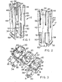
- FIGURES 1 and 2 are perspective views of an electrical terminal of the connector taken from different sides;
- FIGURES 3, 4 and 5 are perspective views of the insulating housing of the connector, taken from above, from one end, and from below, respectively;
- FIGURE 6 is a plan view of the assembled connector;
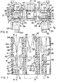
- FIGURE 7 is a cross-sectional view of the connector taken along line 7-7 of Figure 6;
- FIGURE 8 is a cross-sectional view of the connector taken along line 8-8 of Figure 6;
- FIGURE 9 is a cross-sectional view of the connector taken along line 9-9 of Figure 7;
- FIGURE 10 is a fragmentary perspective view of one corner of the connector; and
- FIGURE 11 is a diagrammatic plan view of the base of an automobile head lamp.
- As shown in Figure 11, the
head lamp base 2 has projecting perpendicularly therefrom in a spaced orthogonal array, three flat connectingtabs tabs 6 and 8 being parallel to one another aligned in opposed relation and thetab 4 being positioned between the planes of thetabs 6 and 8 adjacent the edges thereof and extending at right angles thereto. - The connector comprises a rigid
insulating housing 10 moulded from plastics material and three identicalelectrical terminals 12 each of which has been stamped and formed from a single piece of sheet metal stock, e.g., brass stock. - The
housing 10 defines three identical, substantiallyrectangular cavities terminals 12, and each being open at both ends and each communicating with the interior of apocket 20 formed integrally with the upper (as seen in Figures 3 and 4) part of arear wall 22 of thehousing 10. Opposite to eachpocket 20, aforward wall 24 of thehousing 10 is formed with arectilinear slot 26, best seen in Figure 4, which opens into a top, wire-receivingend 27 of thehousing 10 and extends therefrom down to a position level with alower end 28 of theopposed pocket 20. - Projecting from, and formed integrally with, the
wall 24 are twoparallel tab receptacles 30, each of which protrudes into a respective one of thecavities cavity receptacles 30 define tab-receiving slots 31 (Figures 5 and 6) which intersect therespective cavities receptacle 30, outwardly ofwall 24, is tab lockingleaf spring member 34 formed with acatch 33 and restrained against undue flexure by alug 36 of thereceptacle 30, and having arelease handle 35 extending at right angles thereto. - The
cavity 16 communicates with the interior of a further tab receptacle 37 (best seen in Figures 5, 6 and 8) formed integrally with thewall 22 and providing a tab-receivingslot 39, extending longitudinally of thewall 22 and at right angles to thewall 24 andslots 31 and intersecting thecavity 16. - Each
cavity shaped ribs 38 each cooperating with oneadjacent wall housing 10 to define agroove 40, which is closed at its lower (as seen in Figure 3) end by thebase 41 of the L. - As best seen in Figure 10, two support blocks 65 are provided in the corners of the right hand ends of each cavity, at the junctions of the end wall and the forward end
rearward walls terminal locating channel 67 defined byspaced ribs 68 havingramp surfaces 69 which project outwardly and downwardly from the end wall, their lower ends formingterminal anchoring shoulders 70. - As shown in Figures 1 and 2, each
terminal 12 is substantially U-shaped or channel-shaped, comprising a web in the form of aplate 42 and substantiallyparallel side plates plate 42 and each provided at its upper end with awire slot 48 shaped according to the teaching of our French Patent Application No. 79.17039, for receiving a multistranded, insulated lead wire (not shown). There depends from theplate 46, a two-armed, tab-engaging receptacle contact 50 thearms 51 of which havecontact surfaces 52 bowed towards each other for resiliently gripping atab 6 or 8 inserted therebetween. Theplate 46 presents ashoulder 53 adjacent to the root of one of thearms 51. Theplate 44 has depending therefrom a one-armed tab-engaging contact 54 having acontact surface 56 which is bowed away from thereceptacle contact 50. Theplate 42 has, in line with thewire slots 48, an upstandingwire stuffer projection 58, thefree end portion 60 of which is curved over inwardly of theterminal 12. Theplate 42 is formed with a substantially T-shaped anchoring lug 62, depending therefrom, and extending in the same direction as thecontacts - In order to prepare the connector for use, the
terminals 12 are inserted, preferably by means of an automatic machine, with their lower (as seen in Figures 1 and 2) ends leading and with the same angular orientations, intorespective cavities free edge portions 64 of theplates grooves 40 and slide therealong until therespective shoulder 53 is seated on closedend 41 of thegroove 40, as the head of thelug 62 rides over theramp surfaces 69 and engages under theshoulders 70 in a snap action with the shank received in thechannel 67, to secure the terminal in position therein. The receptacle contacts 50 of theterminals 12 so positioned in thecavities outs 32, in alignment with theslots 31 of thereceptacles 30, the planes of thecontacts 50 extending at right angles to theslots 31. Thecontact 54 of theterminal 12 in thecavity 16 extends into the interior of thereceptacle 37. In the case of each of theterminals 12, the twowire slots 48 lie in alignment with thepocket 20 and opposite therectilinear slot 26. - In order to load the connector with insulated lead wires (not shown) one wire is inserted into each pair of
wire slots 48 by means of the wire insertion tooling of an automatic wire insertion machine, so that a free end of the wire extends into thepocket 20, that part of the wire which is to be connected to the lamp switch of the automobile, extending out through theopposite slot 26. The provision of thepockets 20 andslots 26 allows the wire insertion tooling to force each wire down at right angles to its longitudinal axis into the associatedwire slots 48, so that the edges of the slots pierce the insulation of the wire to make electrical connection with the metal core of the wire. The tooling is arranged at the same time to curl over thewire stuffer projection 68 of eachterminal 12 down onto that portion of the wire which extends between the twowire slots 48 of theterminal 12 so that the wire is held down in the wire slots. - In order to mate the connector with the
head lamp base 2, thetabs 6 and 8 thereof are inserted intorespective slots 31 of thereceptacles 30, thetab 4 being inserted into theslot 39 of thereceptacle 37, whereby thetabs 6 and 8 are gripped between thecontact surfaces 52 of thecontacts 50 of theterminals 12 in thecavities tab 4 is resiliently engaged by thecontact surface 56 of thecontact 54 of theterminal 12 in thecavity 16. The connector can be detached from the head lamp by pressing thehandles 35 towards one another and pulling the connector away from thehead lamp base 2. - An advantage of the connector described above is that the terminals are all arranged in line and in the same angular orientation with respect to the housing, so that they can readily be terminated by means of a conventional automatic wire insertion machine. Also, the terminals are identical so that they can be produced by the same stamping and forming press, preferably in the form of a strip of terminals for supply to conventional automatic apparatus for loading the terminals into the housing. The fact that all the terminals are to be angularly oriented in the same way with respect to the housing facilitates the loading operation.
Claims (9)
Applications Claiming Priority (2)
| Application Number | Priority Date | Filing Date | Title |
|---|---|---|---|
| FR8315506A FR2552946B1 (en) | 1983-09-29 | 1983-09-29 | ELECTRICAL CONNECTOR FOR COUPLING WITH THREE TONGS AND TERMINAL FOR THIS CONNECTOR |
| FR8315506 | 1983-09-29 |
Publications (2)
| Publication Number | Publication Date |
|---|---|
| EP0136123A1 true EP0136123A1 (en) | 1985-04-03 |
| EP0136123B1 EP0136123B1 (en) | 1987-11-25 |
Family
ID=9292658
Family Applications (1)
| Application Number | Title | Priority Date | Filing Date |
|---|---|---|---|
| EP84306099A Expired EP0136123B1 (en) | 1983-09-29 | 1984-09-06 | Electrical connector for mating with three orthogonally arranged tabs |
Country Status (7)
| Country | Link |
|---|---|
| US (1) | US4593965A (en) |
| EP (1) | EP0136123B1 (en) |
| JP (1) | JPH0626148B2 (en) |
| BR (1) | BR8404864A (en) |
| DE (1) | DE3467839D1 (en) |
| ES (2) | ES290732Y (en) |
| FR (1) | FR2552946B1 (en) |
Families Citing this family (4)
| Publication number | Priority date | Publication date | Assignee | Title |
|---|---|---|---|---|
| JPS6251661U (en) * | 1985-09-20 | 1987-03-31 | ||
| US5030132A (en) * | 1987-12-17 | 1991-07-09 | Amp Incorporated | Bidirectional insulation displacement electrical contact terminal |
| US5860829A (en) * | 1996-05-31 | 1999-01-19 | The Whitaker Corporation | Cross connect terminal block |
| DE102015218817A1 (en) * | 2015-09-30 | 2017-03-30 | Bayerische Motoren Werke Aktiengesellschaft | Body component with tabbing strap for pre-fixing |
Citations (4)
| Publication number | Priority date | Publication date | Assignee | Title |
|---|---|---|---|---|
| FR1182741A (en) * | 1957-09-13 | 1959-06-29 | Socket for electrical current distribution | |
| BE637850A (en) * | 1962-10-09 | 1963-10-15 | Amp Inc | Insulating casing |
| FR2232100A2 (en) * | 1973-05-31 | 1974-12-27 | Amp Inc | |
| FR2460553A1 (en) * | 1979-06-29 | 1981-01-23 | Amp Inc | ELECTRIC CONTACT MEMBER |
Family Cites Families (9)
| Publication number | Priority date | Publication date | Assignee | Title |
|---|---|---|---|---|
| US2762026A (en) * | 1953-03-05 | 1956-09-04 | Illinois Tool Works | Electrical connector |
| US2980881A (en) * | 1958-04-14 | 1961-04-18 | United Carr Fastener Corp | Connector and snap-in contact therefor |
| US3213407A (en) * | 1963-03-07 | 1965-10-19 | Ite Circuit Breaker Ltd | Plug-in base |
| US3550067A (en) * | 1968-04-29 | 1970-12-22 | Molex Products Co | Electrical receptacle and terminal |
| DE1790065A1 (en) * | 1968-09-05 | 1971-12-02 | Heil Ohg O | Built-in device socket |
| JPS4814592B1 (en) * | 1969-05-22 | 1973-05-08 | ||
| US3874764A (en) * | 1973-10-31 | 1975-04-01 | Amp Inc | Lead assembly |
| US4210382A (en) * | 1979-05-23 | 1980-07-01 | Ford Motor Company | Electrical connector and housing |
| JPS6010273Y2 (en) * | 1980-12-12 | 1985-04-09 | ヒロセ電機株式会社 | Pressure welding connector |
-
1983
- 1983-09-29 FR FR8315506A patent/FR2552946B1/en not_active Expired
-
1984
- 1984-09-06 DE DE8484306099T patent/DE3467839D1/en not_active Expired
- 1984-09-06 EP EP84306099A patent/EP0136123B1/en not_active Expired
- 1984-09-27 BR BR8404864A patent/BR8404864A/en not_active IP Right Cessation
- 1984-09-28 ES ES1984290732U patent/ES290732Y/en not_active Expired
- 1984-09-28 JP JP59203918A patent/JPH0626148B2/en not_active Expired - Lifetime
- 1984-10-01 US US06/656,633 patent/US4593965A/en not_active Expired - Lifetime
-
1985
- 1985-07-31 ES ES1985288473U patent/ES288473Y/en not_active Expired
Patent Citations (4)
| Publication number | Priority date | Publication date | Assignee | Title |
|---|---|---|---|---|
| FR1182741A (en) * | 1957-09-13 | 1959-06-29 | Socket for electrical current distribution | |
| BE637850A (en) * | 1962-10-09 | 1963-10-15 | Amp Inc | Insulating casing |
| FR2232100A2 (en) * | 1973-05-31 | 1974-12-27 | Amp Inc | |
| FR2460553A1 (en) * | 1979-06-29 | 1981-01-23 | Amp Inc | ELECTRIC CONTACT MEMBER |
Also Published As
| Publication number | Publication date |
|---|---|
| ES288473Y (en) | 1986-09-16 |
| FR2552946A1 (en) | 1985-04-05 |
| FR2552946B1 (en) | 1985-12-27 |
| DE3467839D1 (en) | 1988-01-07 |
| US4593965A (en) | 1986-06-10 |
| ES290732U (en) | 1986-10-01 |
| JPS6093775A (en) | 1985-05-25 |
| ES288473U (en) | 1986-02-16 |
| ES290732Y (en) | 1987-06-01 |
| JPH0626148B2 (en) | 1994-04-06 |
| EP0136123B1 (en) | 1987-11-25 |
| BR8404864A (en) | 1985-08-13 |
Similar Documents
| Publication | Publication Date | Title |
|---|---|---|
| US3720907A (en) | Panel connector employing flag-type terminals and terminal extracting tool for the same | |
| US5007865A (en) | Electrical receptacle terminal | |
| US4113341A (en) | Electrical connector having provision for circuit components | |
| EP0017330B1 (en) | A barrier terminal block for the interconnection of electrical wires | |
| EP0021731B1 (en) | Electrical contact member and connector including such contact members | |
| EP0571156A2 (en) | Electrical connector housing assembly and an electrical terminal therefor | |
| EP0039569B1 (en) | Electrical plug receptacle connector | |
| JPS645754B2 (en) | ||
| JPS603745B2 (en) | electrical connector | |
| GB1486404A (en) | Manufacture of electrical harnesses | |
| US5087210A (en) | Wire-to-wire electrical connecting means | |
| EP0191539B1 (en) | Electrical connecting terminal for a connector | |
| US4508410A (en) | Electrical termination system and connector member | |
| EP0610786A2 (en) | Insulation displacement termination system for input-output electrical connector | |
| US4124265A (en) | Quick slide connector | |
| GB1584910A (en) | Electrical connector housing and electrical connector | |
| US5622515A (en) | Grounding electrical leads | |
| EP0390449B1 (en) | Electrical connector | |
| US5433630A (en) | Spring-incorporated flat type terminal structure | |
| US3671925A (en) | Pressure lock and release terminal for an electrical receptacle | |
| EP0136123B1 (en) | Electrical connector for mating with three orthogonally arranged tabs | |
| US4512620A (en) | Mass termination electrical connector | |
| US4413873A (en) | Electrical tab receptacle | |
| EP0446220B1 (en) | Electrical contact | |
| JPS6391970A (en) | Electric connector |
Legal Events
| Date | Code | Title | Description |
|---|---|---|---|
| PUAI | Public reference made under article 153(3) epc to a published international application that has entered the european phase |
Free format text: ORIGINAL CODE: 0009012 |
|
| AK | Designated contracting states |
Designated state(s): BE DE GB IT NL |
|
| 17P | Request for examination filed |
Effective date: 19850927 |
|
| 17Q | First examination report despatched |
Effective date: 19860807 |
|
| ITF | It: translation for a ep patent filed |
Owner name: GUZZI E RAVIZZA S.R.L. |
|
| GRAA | (expected) grant |
Free format text: ORIGINAL CODE: 0009210 |
|
| AK | Designated contracting states |
Kind code of ref document: B1 Designated state(s): BE DE GB IT NL |
|
| REF | Corresponds to: |
Ref document number: 3467839 Country of ref document: DE Date of ref document: 19880107 |
|
| PLBE | No opposition filed within time limit |
Free format text: ORIGINAL CODE: 0009261 |
|
| STAA | Information on the status of an ep patent application or granted ep patent |
Free format text: STATUS: NO OPPOSITION FILED WITHIN TIME LIMIT |
|
| 26N | No opposition filed | ||
| ITTA | It: last paid annual fee | ||
| REG | Reference to a national code |
Ref country code: GB Ref legal event code: 732E |
|
| PGFP | Annual fee paid to national office [announced via postgrant information from national office to epo] |
Ref country code: NL Payment date: 19950707 Year of fee payment: 12 |
|
| PGFP | Annual fee paid to national office [announced via postgrant information from national office to epo] |
Ref country code: BE Payment date: 19951002 Year of fee payment: 12 |
|
| PG25 | Lapsed in a contracting state [announced via postgrant information from national office to epo] |
Ref country code: BE Effective date: 19960930 |
|
| BERE | Be: lapsed |
Owner name: AMP INC. (UNE SOC. DE PENNSYLVANIE) Effective date: 19960930 |
|
| PG25 | Lapsed in a contracting state [announced via postgrant information from national office to epo] |
Ref country code: NL Effective date: 19970401 |
|
| NLV4 | Nl: lapsed or anulled due to non-payment of the annual fee |
Effective date: 19970401 |
|
| PGFP | Annual fee paid to national office [announced via postgrant information from national office to epo] |
Ref country code: GB Payment date: 19980806 Year of fee payment: 15 |
|
| PGFP | Annual fee paid to national office [announced via postgrant information from national office to epo] |
Ref country code: DE Payment date: 19980928 Year of fee payment: 15 |
|
| PG25 | Lapsed in a contracting state [announced via postgrant information from national office to epo] |
Ref country code: GB Free format text: LAPSE BECAUSE OF NON-PAYMENT OF DUE FEES Effective date: 19990906 |
|
| GBPC | Gb: european patent ceased through non-payment of renewal fee |
Effective date: 19990906 |
|
| PG25 | Lapsed in a contracting state [announced via postgrant information from national office to epo] |
Ref country code: DE Free format text: LAPSE BECAUSE OF NON-PAYMENT OF DUE FEES Effective date: 20000701 |