EP0136099A2 - Plastics electrode secondary battery - Google Patents
Plastics electrode secondary battery Download PDFInfo
- Publication number
- EP0136099A2 EP0136099A2 EP84305885A EP84305885A EP0136099A2 EP 0136099 A2 EP0136099 A2 EP 0136099A2 EP 84305885 A EP84305885 A EP 84305885A EP 84305885 A EP84305885 A EP 84305885A EP 0136099 A2 EP0136099 A2 EP 0136099A2
- Authority
- EP
- European Patent Office
- Prior art keywords
- polyacetylene
- electrode
- membranes
- positive
- negative
- Prior art date
- Legal status (The legal status is an assumption and is not a legal conclusion. Google has not performed a legal analysis and makes no representation as to the accuracy of the status listed.)
- Granted
Links
Images

Classifications
-
- H—ELECTRICITY
- H01—ELECTRIC ELEMENTS
- H01M—PROCESSES OR MEANS, e.g. BATTERIES, FOR THE DIRECT CONVERSION OF CHEMICAL ENERGY INTO ELECTRICAL ENERGY
- H01M4/00—Electrodes
- H01M4/02—Electrodes composed of, or comprising, active material
- H01M4/13—Electrodes for accumulators with non-aqueous electrolyte, e.g. for lithium-accumulators; Processes of manufacture thereof
- H01M4/137—Electrodes based on electro-active polymers
-
- H—ELECTRICITY
- H01—ELECTRIC ELEMENTS
- H01M—PROCESSES OR MEANS, e.g. BATTERIES, FOR THE DIRECT CONVERSION OF CHEMICAL ENERGY INTO ELECTRICAL ENERGY
- H01M10/00—Secondary cells; Manufacture thereof
- H01M10/05—Accumulators with non-aqueous electrolyte
-
- H—ELECTRICITY
- H01—ELECTRIC ELEMENTS
- H01M—PROCESSES OR MEANS, e.g. BATTERIES, FOR THE DIRECT CONVERSION OF CHEMICAL ENERGY INTO ELECTRICAL ENERGY
- H01M4/00—Electrodes
- H01M4/02—Electrodes composed of, or comprising, active material
- H01M4/36—Selection of substances as active materials, active masses, active liquids
- H01M4/60—Selection of substances as active materials, active masses, active liquids of organic compounds
-
- Y—GENERAL TAGGING OF NEW TECHNOLOGICAL DEVELOPMENTS; GENERAL TAGGING OF CROSS-SECTIONAL TECHNOLOGIES SPANNING OVER SEVERAL SECTIONS OF THE IPC; TECHNICAL SUBJECTS COVERED BY FORMER USPC CROSS-REFERENCE ART COLLECTIONS [XRACs] AND DIGESTS
- Y02—TECHNOLOGIES OR APPLICATIONS FOR MITIGATION OR ADAPTATION AGAINST CLIMATE CHANGE
- Y02E—REDUCTION OF GREENHOUSE GAS [GHG] EMISSIONS, RELATED TO ENERGY GENERATION, TRANSMISSION OR DISTRIBUTION
- Y02E60/00—Enabling technologies; Technologies with a potential or indirect contribution to GHG emissions mitigation
- Y02E60/10—Energy storage using batteries
Definitions
- This invention is concerned with a plastics electrode secondary battery which employs polyacetylene membranes as the electrodes.
- Polyacetylene is the simplest straight-chain conjugated high-molecular weight compound that contains only carbon and hydrogen and has the properties of a semiconductor.
- Apolyacetylene membrane prepared with a Z i egler-Natta catalyst of the type Ti(OC 4 H 9 ) 4 -Al(C 2 H 5 ) 3 has a fibril (fibrous ultrafine crystal) mesh structure with interstices of approx. 200 ⁇ in diameter. When this membrane is slightly doped with halogen gas or arsenic pentafluoride, its conductivity can be significantly altered.
- polyacetylene membrane Since polyacetylene membrane has extremely good chemical stability, light weight and a fibril mesh structure of large surface area, it has already been noted as a suitable electrode material for use in secondary batteries.
- a conventional plastic electrode secondary battery of this type has a positive polyacetylene membrane electrode, a negative polyacetylene membrane electrode, a separator interposed between the positive electrode and the negative electrode, and an electrolyte comprising a solution of lithium perchlorate (LiC10 4 ) in propylene carbonate.
- Secondary batteries of this type have a voltage of 2.5 V, an energy density of 150 Wh/kg, a maximum output density of 17 Kw/Kg, a power efficiency of 80% and can be charged/discharged approx. 300 times. These characteristics compare favourably with those of a bad storage battery, which has a voltage of 2.1 v, an energy density of 30 Wh/Kg, and can be charged/discharged 200-300 times.
- the secondary battery gives improved performance with a reduction in overall weight.
- a plastics electrode secondary battery which comprises, within a container:
- the positive and negative polyacetylene electrodes each consist of a bonded laminate of a plurality of polyacetylene membranes, rather than single membranes.
- the polyacetylene membranes of the laminated electrodes are so arranged that the surface density of the outer membranes adjacent to the auxiliary electrodes is greater than that of the inner membranes adjacent to the separator.
- the number of polyacetylene membranes in the laminated positive electrode is less than the number of polyacetylene membranes in the laminated negative electrode.
- a plastic electrode secondary battery of the present invention comprises a container 1 formed of an inert synthetic material such as glass or polyethylene, a polyacetylene membrane electrode 4 bonded to a positive auxiliary electrode 9, a polyacetylene membrane electrode 6 bonded to a negative auxiliary electrode 10, a separator 7 comprising a glass fibre film interposed between the positive electrode 4 and the negative electrode 6, and an electrolyte 8 comprising a solution of lithium perchlorate in propylene carbonate sealed in the container 1, the concentration of the solution being IN.
- a bleeder 2 is provided which is capable of exhausting gas externally when the pressure of the gas produced in the container 1 reaches a predetermined value.
- connection 3 and 5 are respectively connected to the auxiliary electrodes 9 and 10, while in Figure 2, the connections 3 and 5 are respectively connected not only to the auxiliary electrodes 9 and 10 but also to the polyacetylene electrodes 4 and 6, the electrodes 9 and 10 being respectively interposed between the electrodes 4 and b and the container 1.
- the surface of the polyacetylene electrode 4 in contact with the auxiliary positive electrode 9 has a film of deposited gold and the surface of the polyacetylene electrode 6 in contact with the auxiliary negative electrode 10 has a film of deposited aluminium.
- the auxiliary electrodes 9 and 10 are respectively bonded to the treated outer surfaces of the polyacetylene electrodes 4 and 6, the inner surfaces of which are in contact with the separator 7, by methods such as press- bonding and supersonic bonding.
- the glass fibre filter of the separator 7 the electrodes 9 and 10 and the container 1 are dried in vacuo, that the PC is dried under reduced pressure, and that the lithium perchlorate is dehydrated in vacuo for 5 hours, then dried under reduced pressure for 24 hours.
- the surface treatment of the polyacetylene electrodes is carried out as follows: gold is heated and deposited at high vacuum as a thin film on that surface of the positive polyacetylene electrode which will be in contact with the auxiliary positive electrode 9 and, similarly, aluminium is heated and deposited at high vacuum as a thin film on that surface of the negative polyacetylene electrode which will be in contact with the auxiliary negative electrode 10.
- a film of gold 4'b is deposited in the surface cavities of the fibril structure of the polyacetylene membrane 4' and a film of aluminium 6'b is deposited in the surface cavities of the polyacetylene membrane 6'.
- the thicknesses of the deposited films 4'b and 6'b are preferably in the range of approx. 0.1 microns to 5 microns.
- the deposition time is kept to a minimum to prevent thermal deterioration of the film.
- polyacetylene membranes 25 ml of toluene, 7.2 ml of triethyl aluminium and 4.5 ml of tetraethoxytitanium are mixed to give the Ziegler-Natta catalyst. The mixture is cooled to -78°C and acetylene gas blown in to give polyacetylene membrane with a thickness of 70 microns and a bulk density of 0.36 g/cm 3 .
- the polyacetylene membrane was then cut into square pieces of 2 cm x 2 cm; gold was deposited on the positive electrode and aluminium was deposited on the negative electrode, to a thickness of approx. 1 micron. These membranes were employed in the secondary battery described above.
- the following table shows the shortcircuiting current for such a battery after charging at 0.25 mA for 30 minutes compared with the shortcircuiting current of a battery without surface treated polyacetylene electrodes.
- the effective areas of contact between the positive and negative polyacetylene electrodes and their respective auxiliary electrodes are greater than those of polyacetylene electrodes which have not been surface treated, thereby increasing the shortcircuiting current. Furthermore, the area of contact between the polyacetylene electrodes and the electrolyte is not affected, so that the battery is capable of withstanding heavy loads.
- the voltage of a secondary battery fabricated as described above is 3.3 to 3.5V, the energy density is 424Kh/Kg, and the maximum output density is 24.5 Kw/Kg, all substantial improvements in performance compared with the conventional plastics electrode secondary battery without auxiliary electrodes.
- the power efficiency remains at 80%.
- the electrode reactions of a secondary battery of this type are shown below in such a manner that an arrow to the right indicates a charging reaction and an arrow to the left indicates a discharging reaction:
- the electrolyte absorption rate of the separator is a relatively high 710%, and the internal resistance a relatively low 7.4 ohms.
- a plurality of polyacetylene membranes instead of a single membrane, are laminated to form the positive and negative electrodes, thereby improving the various characteristics of the secondary battery, which will now be described in more detail with reference to Figure 5.
- the table refers to laminated electrodes with a bulk density of 0.3 g/cm 3 prepared by laminating single membranes with a thickness of 70 - 80 microns at a temperature of -78 0 and a pressure of 1 atmosphere for a laminating time of about five minutes. A charging current of 1mA (0.5 mA/cm ) was used in the tests.
- the polyacetylene membranes are not only laminated as described above, but the surface densities of the individual membranes are suitably selected, thereby improving the characteristics of the battery.
- the fundamental structure of the laminated electrodes is the same as that of Figure 5 except that the surface densities of the outer polyacetylene membranes in contact with the auxiliary positive and negative electrodes 9 and 10 are greater than those of the inner polyacetylene membranes which are in contact with the separator 7.
- two Ziegler-Natta catalysts of the type Ti(OC 4 H 9 ) 4 -Al(C 2 H 5 ) 3 containing 100 and 600 mmol/litre of Ti with a Al:Ti molar ratio of 4:1 are typically employed as the catalysts.
- the lamination of the polyacetylene membranes is performed at a temperature of -78 0 and a pressure of 1 atmosphere.
- a vertical laminating bin is filled with an inert gas and rotated at 100 r.p.m. While the laminating bin sealed with inert gas is being rotated, 1 milli litre of the catalyst with 600 mmol/litre of Ti is dropped from a catalyst inlet to the bottom of the bin. When the catalyst has spread on the bottom surface of the bin, rotation is stopped and, the inert gas is evacuated from the bin. Acetylene gas is then introduced into the bin for 10 min. to produce the first layer of polyacetylene membrane (B).
- membrane A has a low surface density, as shown in Figure 6, while membrane B has a large surface density, as shown in Figure 7.
- membrane B has a substantial fibrous part B" with small cavities B'.
- membrane A has a reduced fibrous part A" and larger cavities A'.
- the polyacetylene membrane B is in contact with the auxiliary positive and negative electrodes 9 and 10 and the polyacetylene membrane A is in contact with the separator 7.
- the following table shows the shortcircuiting current after charging for a battery in which the positive and negative electrodes consisted of laminates of polyacetylene membranes of different surface densities, as described above.
- the charging conditions were 2 mA/cm 2 for 1 hour.
- the Table shows that when the surface densities of the polyacetylene membranes in the laminates of the positive and negative electrodes are increased, thereby increasing the effective areas of contact with both auxiliary electrodes, the shortcircuiting currents are increased.
- the effective areas of contact between the positive and negative electrodes and their respective auxiliary electrodes are greater than those for laminated electrodes in which the polyacetylene membranes have a uniform surface density, thereby increasing the shortcircuiting current. Furthermore, the number of cavities in polyacetylene electrodes of this type is significantly reduced, so that the area of contact between the polyacetylene electrodes and the electrolyte is not affected, and the battery is capable of withstanding heavy loads.
- the fundamental structure of the battery is the same as that of Figure 5 except that the characteristics of the battery are improved and the cost of fabrication is reduced by suitably selecting the number of polyacetylene membranes in the laminated electrodes.
- this preferred embodiment of the invention has substantially the same structure as that shown in Figure 5, wherein the same components are designated by the same or equivalent reference numerals.
- the number of polyacetylene membranes 4, 4 1 , .. in the laminated positive electrode is less than the number of polyacetylene membranes 6, 6 1 .. in the laminated negative electrode.
- the first table shows that after 1 hours' charging the shortcircuiting currents for those batteries in which the ratio of negative membranes to positive membranes was ⁇ 2:1 decreased relative to the corresponding battery with an equal number of negative and positive membranes. On the other hand, substantially unchanged currents were obtained when the ratio of negative membranes to positive membranes was ⁇ 2:1.
- the second table shows that after 3 hours' charging the shortcircuiting currents for those batteries in which the ratio of negative membranes to positive membranes was h 2:1 had also decreased relative to the corresponding battery with an equal number of negative and positive membranes, but to a lesser extent than after 1 hours' charging. Again, substantially unchanged currents were obtained when the ratio of negative membranes to positive membranes was ⁇ 2:1.
- the shortcircuiting current of a battery in which the number of positive membranes is reduced to almost half the number of negative membranes is substantially the same as that of the corresponding battery with an equal number of positive and negative membranes, thereby allowing a saving in the cost of fabrication by reducing the number of membranes required in the laminated positive electrode.
Landscapes
- Chemical & Material Sciences (AREA)
- Chemical Kinetics & Catalysis (AREA)
- Electrochemistry (AREA)
- General Chemical & Material Sciences (AREA)
- Engineering & Computer Science (AREA)
- Materials Engineering (AREA)
- Manufacturing & Machinery (AREA)
- Secondary Cells (AREA)
Abstract
Description
- This invention is concerned with a plastics electrode secondary battery which employs polyacetylene membranes as the electrodes.
- Polyacetylene is the simplest straight-chain conjugated high-molecular weight compound that contains only carbon and hydrogen and has the properties of a semiconductor. Apolyacetylene membrane prepared with a Ziegler-Natta catalyst of the type Ti(OC4H9)4-Al(C2H5)3 has a fibril (fibrous ultrafine crystal) mesh structure with interstices of approx. 200Å in diameter. When this membrane is slightly doped with halogen gas or arsenic pentafluoride, its conductivity can be significantly altered.
- Since polyacetylene membrane has extremely good chemical stability, light weight and a fibril mesh structure of large surface area, it has already been noted as a suitable electrode material for use in secondary batteries.
- A conventional plastic electrode secondary battery of this type has a positive polyacetylene membrane electrode, a negative polyacetylene membrane electrode, a separator interposed between the positive electrode and the negative electrode, and an electrolyte comprising a solution of lithium perchlorate (LiC104) in propylene carbonate. Secondary batteries of this type have a voltage of 2.5 V, an energy density of 150 Wh/kg, a maximum output density of 17 Kw/Kg, a power efficiency of 80% and can be charged/discharged approx. 300 times. These characteristics compare favourably with those of a bad storage battery, which has a voltage of 2.1 v, an energy density of 30 Wh/Kg, and can be charged/discharged 200-300 times. Thus the secondary battery gives improved performance with a reduction in overall weight.
- The performance of the secondary battery described above is not, however, wholly satisfactory. In particular, undesirable reactions tend to take place between the electrodes and the electrolyte which can lead to significant deterioration in the performance of the battery.
- We have now found that such undesirable reactions can be substantially eliminated by the provision of auxiliary metal electrodes bonded to the polyacetylene membrane electrodes of the secondary battery.
- A plastics electrode secondary battery which comprises, within a container:
- a positive electrode comprising a polyacetylene membrane,
- a negative electrode comprising a polyacetylene membrane,
- a separator interposed between the positive electrode and the negative electrode,
- an auxiliary positive electrode bonded to the surface of the positive electrode remote from the separator,
- an auxiliary negative electrode bonded to the surface of the negative electrode remote from the separator, and
- an electrolyte comprising a solution of lithium perchlorate in propylene carbonate.
- In a preferred embodiment of the invention a film of deposited gold is present on the surface of the positive polyacetylene electrode adjacent to the auxiliary positive electrode and a film of deposited aluminium is present on the surface of the negative polyacetylene electrode adjacent to the auxiliary negative electrode.
- In a second preferred embodiment of the invention, the positive and negative polyacetylene electrodes each consist of a bonded laminate of a plurality of polyacetylene membranes, rather than single membranes.
- In a third preferred embodiment of the invention, the polyacetylene membranes of the laminated electrodes are so arranged that the surface density of the outer membranes adjacent to the auxiliary electrodes is greater than that of the inner membranes adjacent to the separator.
- In a fourth preferred embodiment of the invention, the number of polyacetylene membranes in the laminated positive electrode is less than the number of polyacetylene membranes in the laminated negative electrode.
- In order that they may be more fully understood, the invention and preferred embodiments of the invention will now be described, by way of example, with reference to the accompanying drawings, in which:
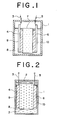
- Figure 1 is a schematic vertical sectional front view of a plastic electrode secondary battery showing a conventional example of the present invention.
- Figure 2 is a schematic vertical sectional front view showing another conventional example of the same invention.
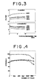
- Figure 3 is a graphical representation showing the relationship between the duration of charging and discharging times and the voltage of the battery;
- Figure 4 is a graphical representation showing the relationship between the number of charge/ discharge cycles performed and the corresponding efficiencies of the voltage, current and electrical power of the battery;
- Figure 5 is a schematic vertical sectional front view of a plastics electrode secondary battery showing a conventional example of a preferred embodiment of the present invention;
- Figure 6 is an enlarged plan view of the polyacetylene membrane which is in contact with the separator of the battery in a preferred embodiment of the present invention, for the purposes of describing the surface density;
- Figure 7 is an enlarged plan view of the polyacetylene membrane which is in contact with the auxiliary electrode of the battery in a preferred embodiment of the present invention, for the purposes of describing the surface density;
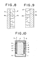
- Figures 8 and 9 are enlarged vertical sectional views of the polyacetylene membranes bonded to the auxiliary positive and negative electrodes according to a preferred embodiment of the present invention; and
- Figure 10 is a schematic vertical front view of a plastic electrode secondary battery showing a conventional example of another preferred embodiment of the present invention.
- The present invention will now be described in more detail with reference to the accompanying drawings.
- A plastic electrode secondary battery of the present invention, as shown in Figures 1 and 2, comprises a container 1 formed of an inert synthetic material such as glass or polyethylene, a
polyacetylene membrane electrode 4 bonded to a positiveauxiliary electrode 9, apolyacetylene membrane electrode 6 bonded to a negativeauxiliary electrode 10, aseparator 7 comprising a glass fibre film interposed between thepositive electrode 4 and thenegative electrode 6, and anelectrolyte 8 comprising a solution of lithium perchlorate in propylene carbonate sealed in the container 1, the concentration of the solution being IN. In Figure 2, ableeder 2 is provided which is capable of exhausting gas externally when the pressure of the gas produced in the container 1 reaches a predetermined value. - In Figure 1, the
connections auxiliary electrodes connections auxiliary electrodes polyacetylene electrodes electrodes electrodes 4 and b and the container 1. - In a preferred embodiment of the invention, the surface of the
polyacetylene electrode 4 in contact with the auxiliarypositive electrode 9 has a film of deposited gold and the surface of thepolyacetylene electrode 6 in contact with the auxiliarynegative electrode 10 has a film of deposited aluminium. Theauxiliary electrodes polyacetylene electrodes separator 7, by methods such as press- bonding and supersonic bonding. - In fabricating the secondary battery described above, it is recommended that the glass fibre filter of the
separator 7, theelectrodes - The surface treatment of the polyacetylene electrodes is carried out as follows: gold is heated and deposited at high vacuum as a thin film on that surface of the positive polyacetylene electrode which will be in contact with the auxiliary
positive electrode 9 and, similarly, aluminium is heated and deposited at high vacuum as a thin film on that surface of the negative polyacetylene electrode which will be in contact with the auxiliarynegative electrode 10. - In this way, as shown in Figures 8 and 9, a film of gold 4'b is deposited in the surface cavities of the fibril structure of the polyacetylene membrane 4' and a film of aluminium 6'b is deposited in the surface cavities of the
polyacetylene membrane 6'. - The thicknesses of the deposited films 4'b and 6'b are preferably in the range of approx. 0.1 microns to 5 microns. The deposition time is kept to a minimum to prevent thermal deterioration of the film.
- To produce the polyacetylene membranes, 25 ml of toluene, 7.2 ml of triethyl aluminium and 4.5 ml of tetraethoxytitanium are mixed to give the Ziegler-Natta catalyst. The mixture is cooled to -78°C and acetylene gas blown in to give polyacetylene membrane with a thickness of 70 microns and a bulk density of 0.36 g/cm3.
- The polyacetylene membrane was then cut into square pieces of 2 cm x 2 cm; gold was deposited on the positive electrode and aluminium was deposited on the negative electrode, to a thickness of approx. 1 micron. These membranes were employed in the secondary battery described above.
- The following table shows the shortcircuiting current for such a battery after charging at 0.25 mA for 30 minutes compared with the shortcircuiting current of a battery without surface treated polyacetylene electrodes.

- Thus a shortcircuiting current of approx. 2.5 times that of a conventional battery was observed with the preferred embodiment.
- In secondary batteries as described above, the effective areas of contact between the positive and negative polyacetylene electrodes and their respective auxiliary electrodes are greater than those of polyacetylene electrodes which have not been surface treated, thereby increasing the shortcircuiting current. Furthermore, the area of contact between the polyacetylene electrodes and the electrolyte is not affected, so that the battery is capable of withstanding heavy loads.
- The voltage of a secondary battery fabricated as described above is 3.3 to 3.5V, the energy density is 424Kh/Kg, and the maximum output density is 24.5 Kw/Kg, all substantial improvements in performance compared with the conventional plastics electrode secondary battery without auxiliary electrodes. The power efficiency remains at 80%.
- The electrode reactions of a secondary battery of this type are shown below in such a manner that an arrow to the right indicates a charging reaction and an arrow to the left indicates a discharging reaction:


- The results of cycle tests in which charging at a constant current of 50 µA/cm was carried out for 10 min. and then discharging at a constant resistance of 50 Kfl for 10 min. are shown in Figure 3 and indicate that the secondary battery could produce 3.3 to 3.5V even after 2,600 charge/discharge cycles, and that though the discharging characteristics slightly deteriorated after about 1300 cycles, no substantial deterioration occurred.
- The effects of the cycle tests on the various efficiencies of the battery are shown in Figure 4. Thus after prolonged cycle testing the voltage efficiency nV, the current efficiency nI, and the power efficiency nP did not drop abruptly from their respective values of 99%, 71% and 70%; on the other hand, when platinum positive and negative auxiliary electrodes were employed without gold and aluminium deposition films on the contact surfaces of the polyacetylene electrodes the discharging characteristics deteriorated rapidly as the number of cycles increased. This is believed to arise from the reaction of lithium ions in the negative auxiliary electrode with impurities in the electrolyte, leading to a progressive deterioration at the surface of the auxiliary electrode. When copper plates were used as the auxiliary electrodes, the cycle test characteristics were relatively stable, but the deterioration of the auxiliary electrodes resulting from reaction with C104 - in the electrolyte could be observed.
- Since a glass fibre filter is used as the separator in the battery according to the present invention, the electrolyte absorption rate of the separator is a relatively high 710%, and the internal resistance a relatively low 7.4 ohms. For these reasons, the current produced in the battery is improved, the fibril structure of the polyactylene membrane is more effectively activated, the movement of the solute ions through this structure is facilitated, and the unwanted reaction at the surface of the electrodes arising from repeated charging and discharging is eliminated, resulting in minimal deterioration in the electric characteristics of the battery.
- In the second preferred embodiment of the invention, a plurality of polyacetylene membranes, instead of a single membrane, are laminated to form the positive and negative electrodes, thereby improving the various characteristics of the secondary battery, which will now be described in more detail with reference to Figure 5.
- Its fundamental structure is the same as that of the battery shown in Figures 1 and 2, wherein the same components in Figure 5 are designated by the same or equivalent reference numerals in Figures 1 and 2 except that a plurality of
polyacetylene membranes 4, 4', .. and 6, 61, .. bonded in a laminated state are equivalent to the positivepolyacetylene membrane electrode 4 and the negativepolyacetylene membrane electrode 6 respectively. The laminated polyacetylene electrodes have a thickness of 50 to 150 microns, a bulk density of 0.4 g/cc, and a conductivity of 10-9 S/cm. The means by which the polyacetylene membranes are bonded to one another include press bonding and supersonic bonding, in the same way as the polyacetylene membrane electrodes are bonded to the auxiliary electrodes. - It has been found that when both the positive and negative electrodes of the battery consist of laminated polyacetylene membranes instead of single membranes, there is a significant increase in the shortcircuiting current of the battery after charging (see Table below).
- The table refers to laminated electrodes with a bulk density of 0.3 g/cm3 prepared by laminating single membranes with a thickness of 70 - 80 microns at a temperature of -780 and a pressure of 1 atmosphere for a laminating time of about five minutes. A charging current of 1mA (0.5 mA/cm ) was used in the tests.

- The reason the shortcircuiting current is increased by the lamination of the polyacetylene membranes is believed to be that improved ionic mobility through the laminate increases the ability to retain charge, whilst also allowing almost complete discharging to be carried out. The improved ionic mobility in the laminate arises from the fibril structure of the membrane with its many small interstices.
- In a third preferred embodiment of the plastic electrode secondary battery of the invention, the polyacetylene membranes are not only laminated as described above, but the surface densities of the individual membranes are suitably selected, thereby improving the characteristics of the battery.
- The fundamental structure of the laminated electrodes is the same as that of Figure 5 except that the surface densities of the outer polyacetylene membranes in contact with the auxiliary positive and
negative electrodes separator 7. - To fabricate the laminated polyacetylene membranes described above, two Ziegler-Natta catalysts of the type Ti(OC4H9)4-Al(C2H5)3 containing 100 and 600 mmol/litre of Ti with a Al:Ti molar ratio of 4:1 are typically employed as the catalysts.
- The lamination of the polyacetylene membranes is performed at a temperature of -780 and a pressure of 1 atmosphere.
- To fabricate the laminated polyacetylene electrode, a vertical laminating bin, not shown, is filled with an inert gas and rotated at 100 r.p.m. While the laminating bin sealed with inert gas is being rotated, 1 milli litre of the catalyst with 600 mmol/litre of Ti is dropped from a catalyst inlet to the bottom of the bin. When the catalyst has spread on the bottom surface of the bin, rotation is stopped and, the inert gas is evacuated from the bin. Acetylene gas is then introduced into the bin for 10 min. to produce the first layer of polyacetylene membrane (B).
- The bin is again rotated, 1 milli litre of the catalyst with 100 mmol/litre of Ti is dropped from the inlet onto the first layer of polyacetylene membrane in the bin, and the procedure completed as before to produce a second layer of polyacetylene membrane (A) laminated to the first layer B but of a different surface density. In this case, membrane A has a low surface density, as shown in Figure 6, while membrane B has a large surface density, as shown in Figure 7. Specifically, membrane B has a substantial fibrous part B" with small cavities B'. On the other hand, membrane A has a reduced fibrous part A" and larger cavities A'.
- In the battery, the polyacetylene membrane B is in contact with the auxiliary positive and
negative electrodes separator 7. - The following table shows the shortcircuiting current after charging for a battery in which the positive and negative electrodes consisted of laminates of polyacetylene membranes of different surface densities, as described above. The charging conditions were 2 mA/cm2 for 1 hour.

- The Table shows that when the surface densities of the polyacetylene membranes in the laminates of the positive and negative electrodes are increased, thereby increasing the effective areas of contact with both auxiliary electrodes, the shortcircuiting currents are increased.
- In the embodiment of the secondary battery described above, the effective areas of contact between the positive and negative electrodes and their respective auxiliary electrodes are greater than those for laminated electrodes in which the polyacetylene membranes have a uniform surface density, thereby increasing the shortcircuiting current. Furthermore, the number of cavities in polyacetylene electrodes of this type is significantly reduced, so that the area of contact between the polyacetylene electrodes and the electrolyte is not affected, and the battery is capable of withstanding heavy loads.
- In a third preferred embodiment of the invention, the fundamental structure of the battery is the same as that of Figure 5 except that the characteristics of the battery are improved and the cost of fabrication is reduced by suitably selecting the number of polyacetylene membranes in the laminated electrodes.
- Referring to Figure 10, this preferred embodiment of the invention has substantially the same structure as that shown in Figure 5, wherein the same components are designated by the same or equivalent reference numerals. In this embodiment of the battery, the number of
polyacetylene membranes polyacetylene membranes - The following two tables show the shortcircuiting currents after charging for 1 hour and 3 hours for batteries containing varying numbers of polyacetylenic membranes in the two laminated electrodes.


- In the above two Tables, the shortcircuiting currents of those batteries which have an equal number of polyacetylene membranes in the positive and negative electrodes are indicated in the left columns.
- The first table shows that after 1 hours' charging the shortcircuiting currents for those batteries in which the ratio of negative membranes to positive membranes was ≥ 2:1 decreased relative to the corresponding battery with an equal number of negative and positive membranes. On the other hand, substantially unchanged currents were obtained when the ratio of negative membranes to positive membranes was < 2:1.
- The second table shows that after 3 hours' charging the shortcircuiting currents for those batteries in which the ratio of negative membranes to positive membranes was h 2:1 had also decreased relative to the corresponding battery with an equal number of negative and positive membranes, but to a lesser extent than after 1 hours' charging. Again, substantially unchanged currents were obtained when the ratio of negative membranes to positive membranes was < 2:1.
- With both charging times it was found that as the ratio of negative membranes to positive membranes was increased beyond 2:1, the decrease in the shortcircuiting current tended to a maximum of 15%.
- The reason the shortcircuiting current of the battery decreased as the ratio of negative membranes to positive membranes exceeds 2:1 is believed to arise from the presence of lithium ions in the negative electrode which react with impurities in the electrolyte, thereby reducing the shortcircuiting current. Increasing the proportion of membranes in the laminated negative electrode increases the surface area of the electrode at which this unwanted reaction can occur and causes a decrease in the shortcircuiting current. However, since lithium ions are absent from the positive electrode, reducing the proportion of positive membranes has no effect on the shortcircuiting current until the number of positive membranes is reduced to half the number of negative membranes.
- According to the embodiment of the invention described above, the shortcircuiting current of a battery in which the number of positive membranes is reduced to almost half the number of negative membranes is substantially the same as that of the corresponding battery with an equal number of positive and negative membranes, thereby allowing a saving in the cost of fabrication by reducing the number of membranes required in the laminated positive electrode.
Claims (5)
Applications Claiming Priority (6)
| Application Number | Priority Date | Filing Date | Title |
|---|---|---|---|
| JP1983134885U JPS6042269U (en) | 1983-08-31 | 1983-08-31 | plastic electrode secondary battery |
| JP134885/83U | 1983-08-31 | ||
| JP1984037530U JPS60150777U (en) | 1984-03-16 | 1984-03-16 | plastic electrode secondary battery |
| JP1984037531U JPS60150778U (en) | 1984-03-16 | 1984-03-16 | plastic electrode secondary battery |
| JP37531/84U | 1984-03-16 | ||
| JP37530/84U | 1984-03-16 |
Publications (3)
| Publication Number | Publication Date |
|---|---|
| EP0136099A2 true EP0136099A2 (en) | 1985-04-03 |
| EP0136099A3 EP0136099A3 (en) | 1987-04-15 |
| EP0136099B1 EP0136099B1 (en) | 1989-10-25 |
Family
ID=27289499
Family Applications (1)
| Application Number | Title | Priority Date | Filing Date |
|---|---|---|---|
| EP84305885A Expired EP0136099B1 (en) | 1983-08-31 | 1984-08-29 | Plastics electrode secondary battery |
Country Status (2)
| Country | Link |
|---|---|
| EP (1) | EP0136099B1 (en) |
| DE (1) | DE3480312D1 (en) |
Cited By (2)
| Publication number | Priority date | Publication date | Assignee | Title |
|---|---|---|---|---|
| EP0237729A1 (en) * | 1986-03-06 | 1987-09-23 | VARTA Batterie Aktiengesellschaft | Electrochemical storage cell containing at least one polymeric electrode |
| CN113273015A (en) * | 2019-01-10 | 2021-08-17 | Tdk株式会社 | All-solid-state battery |
Family Cites Families (3)
| Publication number | Priority date | Publication date | Assignee | Title |
|---|---|---|---|---|
| FR2502401A1 (en) * | 1981-03-20 | 1982-09-24 | Centre Nat Rech Scient | NOVEL SOLID ELECTROCHEMICAL GENERATORS, PROCESSES FOR THE PREPARATION OF SUCH GENERATORS, AND GENERATOR DRAWINGS FOR CARRYING OUT SAID METHODS |
| DE3201482A1 (en) * | 1982-01-20 | 1983-09-08 | Bayer Ag, 5090 Leverkusen | MULTI-LAYER AREA |
| JPS5973864A (en) * | 1982-10-20 | 1984-04-26 | Showa Denko Kk | Laminated sheet-shaped polymer secondary battery |
-
1984
- 1984-08-29 DE DE8484305885T patent/DE3480312D1/en not_active Expired
- 1984-08-29 EP EP84305885A patent/EP0136099B1/en not_active Expired
Cited By (4)
| Publication number | Priority date | Publication date | Assignee | Title |
|---|---|---|---|---|
| EP0237729A1 (en) * | 1986-03-06 | 1987-09-23 | VARTA Batterie Aktiengesellschaft | Electrochemical storage cell containing at least one polymeric electrode |
| US4816359A (en) * | 1986-03-06 | 1989-03-28 | Varta Batterie Aktiengesellschaft | Electrochemical secondary element with at least one polymer electrode |
| CN113273015A (en) * | 2019-01-10 | 2021-08-17 | Tdk株式会社 | All-solid-state battery |
| CN113273015B (en) * | 2019-01-10 | 2023-11-21 | Tdk株式会社 | All solid battery |
Also Published As
| Publication number | Publication date |
|---|---|
| EP0136099A3 (en) | 1987-04-15 |
| EP0136099B1 (en) | 1989-10-25 |
| DE3480312D1 (en) | 1989-11-30 |
Similar Documents
| Publication | Publication Date | Title |
|---|---|---|
| CN1137522C (en) | Multi-layer type nonaqueous electrolyte secondary cell | |
| US5348817A (en) | Bipolar lead-acid battery | |
| US5498489A (en) | Rechargeable non-aqueous lithium battery having stacked electrochemical cells | |
| US8021775B2 (en) | Cell structure for electrochemical devices and method of making same | |
| US7195840B2 (en) | Cell structure for electrochemical devices and method of making same | |
| JP3722797B2 (en) | Electrolyte-containing granular electrode for lithium storage battery | |
| CN1170327C (en) | Composite electrode comprising a PTC polymer | |
| KR101440973B1 (en) | Electrode assembly, battery cell and device comprising the same | |
| KR100413608B1 (en) | Separator for lithium ion secondary batteries, method for producing the same, and lithium ion secondary batteries using the same | |
| JP3056054B2 (en) | Zinc secondary battery and zinc electrode | |
| MXPA98000869A (en) | Lithium ion battery, rechargeable, low resistance | |
| EP0842547A1 (en) | Low resistance rechargeable lithium-ion battery | |
| JP2004095400A (en) | Bipolar battery and control method thereof | |
| CA2331485A1 (en) | Bi-cell separation for improved safety | |
| JP7334693B2 (en) | power storage device | |
| JPH1083839A (en) | Electrode product | |
| EP0136099B1 (en) | Plastics electrode secondary battery | |
| KR102008392B1 (en) | A method for manufacturing electrode assembly and a electrode assembly manufactured by the method applied electrochemical device | |
| JP7543884B2 (en) | Lithium-ion secondary battery | |
| JP3428184B2 (en) | Non-aqueous electrolyte secondary battery | |
| EP0347910A1 (en) | A thin ribbonlike flexible rechargeable zinc/halide cell | |
| JPH10112305A (en) | Non-aqueous electrolyte secondary battery and method of manufacturing the same | |
| WO2003100901A1 (en) | Lithium secondary battery and its fabrication | |
| JPH07161379A (en) | Polymer solid electrolyte lithium secondary battery | |
| JPS61250970A (en) | Plastic electrode secondary battery |
Legal Events
| Date | Code | Title | Description |
|---|---|---|---|
| PUAI | Public reference made under article 153(3) epc to a published international application that has entered the european phase |
Free format text: ORIGINAL CODE: 0009012 |
|
| AK | Designated contracting states |
Designated state(s): DE FR GB |
|
| PUAL | Search report despatched |
Free format text: ORIGINAL CODE: 0009013 |
|
| AK | Designated contracting states |
Kind code of ref document: A3 Designated state(s): DE FR GB |
|
| 17P | Request for examination filed |
Effective date: 19870611 |
|
| 17Q | First examination report despatched |
Effective date: 19880613 |
|
| GRAA | (expected) grant |
Free format text: ORIGINAL CODE: 0009210 |
|
| AK | Designated contracting states |
Kind code of ref document: B1 Designated state(s): DE FR GB |
|
| REF | Corresponds to: |
Ref document number: 3480312 Country of ref document: DE Date of ref document: 19891130 |
|
| ET | Fr: translation filed | ||
| PLBE | No opposition filed within time limit |
Free format text: ORIGINAL CODE: 0009261 |
|
| STAA | Information on the status of an ep patent application or granted ep patent |
Free format text: STATUS: NO OPPOSITION FILED WITHIN TIME LIMIT |
|
| 26N | No opposition filed | ||
| PGFP | Annual fee paid to national office [announced via postgrant information from national office to epo] |
Ref country code: FR Payment date: 19970811 Year of fee payment: 14 |
|
| PGFP | Annual fee paid to national office [announced via postgrant information from national office to epo] |
Ref country code: GB Payment date: 19970820 Year of fee payment: 14 |
|
| PGFP | Annual fee paid to national office [announced via postgrant information from national office to epo] |
Ref country code: DE Payment date: 19970905 Year of fee payment: 14 |
|
| PG25 | Lapsed in a contracting state [announced via postgrant information from national office to epo] |
Ref country code: GB Free format text: LAPSE BECAUSE OF NON-PAYMENT OF DUE FEES Effective date: 19980829 |
|
| GBPC | Gb: european patent ceased through non-payment of renewal fee |
Effective date: 19980829 |
|
| PG25 | Lapsed in a contracting state [announced via postgrant information from national office to epo] |
Ref country code: FR Free format text: LAPSE BECAUSE OF NON-PAYMENT OF DUE FEES Effective date: 19990430 |
|
| PG25 | Lapsed in a contracting state [announced via postgrant information from national office to epo] |
Ref country code: DE Free format text: LAPSE BECAUSE OF NON-PAYMENT OF DUE FEES Effective date: 19990601 |
|
| REG | Reference to a national code |
Ref country code: FR Ref legal event code: ST |