EP0135892A2 - Lateral sealer device for vertical packaging machine - Google Patents
Lateral sealer device for vertical packaging machine Download PDFInfo
- Publication number
- EP0135892A2 EP0135892A2 EP84110957A EP84110957A EP0135892A2 EP 0135892 A2 EP0135892 A2 EP 0135892A2 EP 84110957 A EP84110957 A EP 84110957A EP 84110957 A EP84110957 A EP 84110957A EP 0135892 A2 EP0135892 A2 EP 0135892A2
- Authority
- EP
- European Patent Office
- Prior art keywords
- lateral sealer
- lateral
- frame
- sealer
- packaging machine
- Prior art date
- Legal status (The legal status is an assumption and is not a legal conclusion. Google has not performed a legal analysis and makes no representation as to the accuracy of the status listed.)
- Granted
Links
Images


Classifications
-
- B—PERFORMING OPERATIONS; TRANSPORTING
- B65—CONVEYING; PACKING; STORING; HANDLING THIN OR FILAMENTARY MATERIAL
- B65B—MACHINES, APPARATUS OR DEVICES FOR, OR METHODS OF, PACKAGING ARTICLES OR MATERIALS; UNPACKING
- B65B51/00—Devices for, or methods of, sealing or securing package folds or closures; Devices for gathering or twisting wrappers, or necks of bags
- B65B51/10—Applying or generating heat or pressure or combinations thereof
- B65B51/26—Devices specially adapted for producing transverse or longitudinal seams in webs or tubes
- B65B51/30—Devices, e.g. jaws, for applying pressure and heat, e.g. for subdividing filled tubes
- B65B51/303—Devices, e.g. jaws, for applying pressure and heat, e.g. for subdividing filled tubes reciprocating along only one axis
Definitions
- the packaging of articles using a strip of film 1 is done in one of four sealing modes, which include a back-seal mode in which each package has a vertical seal in the center of the rear surface thereof, a modified back-seal mode in which each package has a vertical seal positioned on the rear surface but some distance to the right or left from the center thereof, a triple-seal mode in which each package has a vertical seal along one edge thereof, and a quadruple-seal mode in which each package has vertical seals along two edges thereof.
- four sealing modes which include a back-seal mode in which each package has a vertical seal in the center of the rear surface thereof, a modified back-seal mode in which each package has a vertical seal positioned on the rear surface but some distance to the right or left from the center thereof, a triple-seal mode in which each package has a vertical seal along one edge thereof, and a quadruple-seal mode in which each package has vertical seals along two edges thereof.
- An object of the present invention is to provide an excellent lateral-sealer device for a vertical packaging machine which is capable of solving these technical problems encountered in prior-art packaging machines, enables a single packaging machine to select any desired packaging mode as necessary, and which contributes greatly to fields using packaging machines in the distribution industry.
- the strip of film 1 is introduced at a desired tension into a film former 2 where it is formed into a cylindrical shape.
- a supply pipe 4 through which articles (not shown) being packaged are supplied into packages 3 is inserted through the film former 2, and the strip of film 1 is would in a cylindrical form continuously around the outer circumferential surface of the supply pipe 4 by the film former 2.
- a vertical sealer 5 is provided so as to extend along the film former 2.
- the vertical sealer 5 overlaps the two edge portions of the cylindrically-formed strip of film 1, heat-bond them together in a predetermined manner, and thereby shape the strip of film 1 into a completed cylindrical form.
- a lateral sealer 6 is provided below the lower end of the supply pipe 4 and is designed to be rotated in the following manner, according to the packaging modes shown in Figs. 1, 2, 3 and 4, and fixed in predetermined positions.
- the lateral sealer 6 is provided with a rotatable frame 8 supported on a fixed frame 7 projecting from a predetermined portion of the main frame of the packaging machine, and a lateral sealer frame 9 attached to the upper surface of the rotatable frame 8.
- the orientation of the lateral sealer can be varied, as shown in Figs. 1-4, by the movement of the rotatable frame 8.
- a fixing member 10 engages with the rotatable frame 8 and is fastened to the fixed frame 7 by bolts 11, fixing the rotatable frame 8.
- the fixing member 10 is loosened, the frame 8 becomes rotatable.
- the lateral sealer frame 9 is provided with two parallel guide rods 12 which are supported thereon, and two slidable members 13 are fitted around each of the guide rods 12.
- Lateral sealer members 14 are provided between pairs of opposite slidable members 13, the two lateral sealer members 14 move toward and away from each other to seal each package 3 made of the strip of film 1 laterally in a desired manner.
- the length of the lateral sealer members 14 is determined to be equal to or greater than the width of the package 3 when flattened.
- the rack 17 is moved reciproactingly in a linear direction by a predetermined type of reciprocating actuator, consisting of a cylinder or the like, so that the pivotable shaft 15 is rotated forward and backward alternately within a predetermined angular range, by the engagement of the rack 17 and pinion 16.
- a predetermined type of reciprocating actuator consisting of a cylinder or the like
- a crank 19 is attached to each end of the pivotable shaft 15, as shown in Figs. 8 and 9, and two links 21, 22 are connected pivotably by pins 20 to opposite ends of each of the cranks 19.
- One link 21 of the links 21, 22 is short and' extends linearly, while the other 22 is long and curved.
- the inner end of each short link 21 is connected pivotably to the corresponding slidable member 13 to which the lateral sealer member 14 closer to the pivotable shaft 15 is attached, and the inner end of each long link 22 to the corresponding slidable member 13 to which the other lateral sealer member 14 is attached. Accordingly, when the pivotable shaft l5 is rotated forward and backward by the meshing of the actuator 18, rack 17, and pinion 16, the slidable members 13 are slid toward and away from each other along the guide rods 12 by the cranks 19 and the short and long links 21, 22, to open and close the two opposed lateral sealer members 14 and seal the package 3 laterally.
- a pair of molding seal rollers 24 are provided in an opposed relationship either side of the molding plate 23.
- the bulge in the package 3, as well as the back portion and both edges thereof, are sealed, i.e., quadruple-sealing of the packages 3 is done in this manner.
- the lateral sealer 6 is set so that the lateral sealer members thereof extend at right angles to the direction in which the strip of film 1 moves along the supply pipe 4, i.e., horizontally in the lateral direction.
- the articles are then packaged by the lateral sealer 6 and the vertical sealer.
- the lateral sealer is displaced through a desired angle with respect to the axis of the path along which the strip of film 1 is supplied, as shown in Fig. 2.
- the lateral sealer When packaging articles in the triple-seal mode shown in Fig. 3, the lateral sealer is rotated further in the above manner and is set at a position which is 90° from the position in which the package-sealing operation is done in the standard back-seal mode.
- the molding plate 23 is not attached to the rear surface of the supply pipe 4.
Abstract
Description
- This invention relates to a lateral sealer device for a vertical packaging machine which is provided with a lateral sealer which can be rotated and fixed at any desired angular position, and more particularly to a lateral sealer device for a vertical packaging machine which enables one packaging machine to seal articles in a suitable sealing mode selected as necessary from a variety of sealing modes, so as to meet various packaging requirements.
- As is generally known, the packaging of articles using a strip of film 1 is done in one of four sealing modes, which include a back-seal mode in which each package has a vertical seal in the center of the rear surface thereof, a modified back-seal mode in which each package has a vertical seal positioned on the rear surface but some distance to the right or left from the center thereof, a triple-seal mode in which each package has a vertical seal along one edge thereof, and a quadruple-seal mode in which each package has vertical seals along two edges thereof.
- Article are packaged in a strip of film by a special packaging machine suited to the packaging mode in which the articles are sealed in one of the four ways described above.
- Accordingly, different packaging machines for each of the various packaging modes are required. This increases the cost of the equipment and the area in which the packaging machines are installed.
- An object of the present invention is to provide an excellent lateral-sealer device for a vertical packaging machine which is capable of solving these technical problems encountered in prior-art packaging machines, enables a single packaging machine to select any desired packaging mode as necessary, and which contributes greatly to fields using packaging machines in the distribution industry.
-
- Figs. 1-4 are perspective views of various packaging modes;
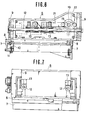
- Fig. 5 is a horizontally-sectioned view of a lateral sealer device;
- Fig. 6 is a longitudinally-sectioned front elevation of the sealer device;
- Fig. 7 is a side elevation of the sealer device;
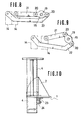
- Figs. 8 and 9 are side elevations of a crank link; and
- Fig. 10 is a side elevation of a film former.
- An embodiment of the present invention will now be described with reference to Fig. 5 onward, as well as Figs. 1-4.
- Referring to the illustrated embodiment, reference numeral 1 denotes a packaging film in the shape of a strip of a predetermined width, which usually consists of an elongated strip of film rolled up into a cylindrical form.
- The strip of film 1 is introduced at a desired tension into a film former 2 where it is formed into a cylindrical shape. A
supply pipe 4 through which articles (not shown) being packaged are supplied into packages 3 is inserted through the film former 2, and the strip of film 1 is would in a cylindrical form continuously around the outer circumferential surface of thesupply pipe 4 by the film former 2. - This packaging method does not differ substantially from the existing packaging methods.
- A
vertical sealer 5 is provided so as to extend along the film former 2. Thevertical sealer 5 overlaps the two edge portions of the cylindrically-formed strip of film 1, heat-bond them together in a predetermined manner, and thereby shape the strip of film 1 into a completed cylindrical form. - In this step, the strip of film 1 may be supplied intermittently at a pitch which is equal to the length of the
vertical sealer 5, so that the edge portions thereof are heat-bonded successively by thevertical sealer 5. On the other hand, a packaging method in which the strip of film 1 is supplied continuously and the edge portions thereof are heat-bonded by thevertical sealer 5 as it moves reciprocatingly in the vertical direction can also be employed. - The edges of the strip of film 1 are thus heat-bonded in the same manner as in a conventional packaging machine, i.e., so-called "back-sealing" is done on the outer circumferential portion of the
feed pipe 4. - A
lateral sealer 6 is provided below the lower end of thesupply pipe 4 and is designed to be rotated in the following manner, according to the packaging modes shown in Figs. 1, 2, 3 and 4, and fixed in predetermined positions. - As shown.in Figs. 6 and 7, the
lateral sealer 6 is provided with arotatable frame 8 supported on a fixedframe 7 projecting from a predetermined portion of the main frame of the packaging machine, and alateral sealer frame 9 attached to the upper surface of therotatable frame 8. The orientation of the lateral sealer can be varied, as shown in Figs. 1-4, by the movement of therotatable frame 8. - As shown in Fig. 6, a
fixing member 10 engages with therotatable frame 8 and is fastened to the fixedframe 7 bybolts 11, fixing therotatable frame 8. When thefixing member 10 is loosened, theframe 8 becomes rotatable. - As shown in Figs. 5 and 6, the
lateral sealer frame 9 is provided with twoparallel guide rods 12 which are supported thereon, and twoslidable members 13 are fitted around each of theguide rods 12.Lateral sealer members 14 are provided between pairs of oppositeslidable members 13, the twolateral sealer members 14 move toward and away from each other to seal each package 3 made of the strip of film 1 laterally in a desired manner. - The length of the
lateral sealer members 14 is determined to be equal to or greater than the width of the package 3 when flattened. - The movements of the
lateral sealer members 14 toward and away from each other are done in accordance with the pivotal movements of apivotable shaft 15 which is provided so as to extend parallel to thelateral sealer frame 9 and cross a portion of each of theguide rods 12 on one side of thelateral sealer frame 9. A pinion is attached to one end of thepivotable shaft 15, and meshes with arack 17. - The
rack 17 is moved reciproactingly in a linear direction by a predetermined type of reciprocating actuator, consisting of a cylinder or the like, so that thepivotable shaft 15 is rotated forward and backward alternately within a predetermined angular range, by the engagement of therack 17 andpinion 16. - A
crank 19 is attached to each end of thepivotable shaft 15, as shown in Figs. 8 and 9, and twolinks pins 20 to opposite ends of each of thecranks 19. - One
link 21 of thelinks short link 21 is connected pivotably to the correspondingslidable member 13 to which thelateral sealer member 14 closer to thepivotable shaft 15 is attached, and the inner end of eachlong link 22 to the correspondingslidable member 13 to which the otherlateral sealer member 14 is attached. Accordingly, when the pivotable shaft l5 is rotated forward and backward by the meshing of theactuator 18,rack 17, andpinion 16, theslidable members 13 are slid toward and away from each other along theguide rods 12 by thecranks 19 and the short andlong links lateral sealer members 14 and seal the package 3 laterally. - A
molding plate 23, which is attached to the supply pipe and used for quadruple-sealing of packages, is provided removably on the rear side of thesupply pipe 4, i.e., on the portion of thesupply pipe 4 which is opposite to the vertical seal, as shown in Fig. 10. A pair ofmolding seal rollers 24 are provided in an opposed relationship either side of themolding plate 23. Part of the film which has been curved into a cylinder on the outer circumferential surface of thesupply pipe 4 so that its edges meet, i.e., a portion of the cylindrically-formed film which is on the opposite side of sealed portion on the back of the package, is bulged outward by themolding plate 23. This bulged portion is compressed and heat-bonded by themolding seal rollers 24. The bulge in the package 3, as well as the back portion and both edges thereof, are sealed, i.e., quadruple-sealing of the packages 3 is done in this manner. - In order to package articles in the standard back-seal mode shown in Fig. 1, using the
lateral sealer 6% of this construction, thelateral sealer 6 is set so that the lateral sealer members thereof extend at right angles to the direction in which the strip of film 1 moves along thesupply pipe 4, i.e., horizontally in the lateral direction. The articles are then packaged by thelateral sealer 6 and the vertical sealer. - When packaging articles in the modified back-sealing mode in which back seal of a package 3 is offset slightly to the right or left from the center of the rear surface thereof, the
fixing member 10 is loosened, as previously mentioned, and therotatable frame 8 is rotated far enough to correspond to the distance by which the seal on the rear surface of the package is offset from the center thereof. Thefixing member 10 is then secured to fix therotatable frame 8. The packaging of articles in the modified back-seal mode can then be carried out easily. - In this package-sealing operation, the lateral sealer is displaced through a desired angle with respect to the axis of the path along which the strip of film 1 is supplied, as shown in Fig. 2.
- When packaging articles in the triple-seal mode shown in Fig. 3, the lateral sealer is rotated further in the above manner and is set at a position which is 90° from the position in which the package-sealing operation is done in the standard back-seal mode.
- When packaging articles in the standard back-seal mode, modified back-seal mode and triple-seal mode, the
molding plate 23 is not attached to the rear surface of thesupply pipe 4. - In order to provide quadruple-seal packaging using the same packaging machine, the molding plate may be attached to the rear surface of the
supply pipe 4, in accordance with the quadruple-seal system shown in Fig. 4. (Effect of the Invention) - According to the present invention described above, a lateral sealer is so arranged that it can be rotated to any desired angle about an axis extending in the direction in which a strip of film is supplied. When the lateral sealer is rotated and the angle thereof is regulated so that it is set at a suitable position, in accordance with the packaging mode being employed, the orientation thereof can be varied in four ways, enabling the packaging of articles by one packaging machine in four different modes, i.e., a back-seal mode, a modified back-seal mode, a triple-seal mode, and a quadruple-seal mode, so that any of these packaging modes can be selected as required. The construction and operation of the lateral sealer device according to the present invention are very simple, so that the device can be used very easily.
Claims (6)
Applications Claiming Priority (2)
| Application Number | Priority Date | Filing Date | Title |
|---|---|---|---|
| JP171760/83 | 1983-09-16 | ||
| JP58171760A JPS6068236A (en) | 1983-09-16 | 1983-09-16 | Lateral sealer device in vertical type packer |
Publications (3)
| Publication Number | Publication Date |
|---|---|
| EP0135892A2 true EP0135892A2 (en) | 1985-04-03 |
| EP0135892A3 EP0135892A3 (en) | 1986-05-21 |
| EP0135892B1 EP0135892B1 (en) | 1990-01-03 |
Family
ID=15929168
Family Applications (1)
| Application Number | Title | Priority Date | Filing Date |
|---|---|---|---|
| EP84110957A Expired EP0135892B1 (en) | 1983-09-16 | 1984-09-13 | Lateral sealer device for vertical packaging machine |
Country Status (4)
| Country | Link |
|---|---|
| US (1) | US4598533A (en) |
| EP (1) | EP0135892B1 (en) |
| JP (1) | JPS6068236A (en) |
| DE (1) | DE3480915D1 (en) |
Cited By (4)
| Publication number | Priority date | Publication date | Assignee | Title |
|---|---|---|---|---|
| GB2164316A (en) * | 1984-09-13 | 1986-03-19 | Focke & Co | Wrapping for bagpacks and a process and apparatus for producing it |
| GB2260114A (en) * | 1991-09-27 | 1993-04-07 | Weigh Systems Limited Sa | Sealing head for a packaging machine |
| WO2001005662A1 (en) * | 1999-07-14 | 2001-01-25 | Unilever Plc | Apparatus for attaching a tag and a thread to a web of filter material |
| ES2318993A1 (en) * | 2005-10-21 | 2009-05-01 | T.M.E. S.R.L. | Device for filling, closing and separating containers containing bulk material (Machine-translation by Google Translate, not legally binding) |
Families Citing this family (11)
| Publication number | Priority date | Publication date | Assignee | Title |
|---|---|---|---|---|
| WO1988002334A1 (en) * | 1986-10-03 | 1988-04-07 | Moran Michael J | Drive mechanism for a bag former |
| DE19603371B4 (en) * | 1996-01-31 | 2006-12-14 | Rovema - Verpackungsmaschinen Gmbh | Tubular bag machine with an asymmetric forming shoulder for the production of tubular bags |
| DE19647277C2 (en) * | 1996-11-15 | 2003-06-18 | Buehler Optima Maschf | Closing device for a packaging machine |
| GB9626745D0 (en) * | 1996-12-23 | 1997-02-12 | Ishida Seisakusho | Form-fill-seal packaging machine |
| DE19725526A1 (en) * | 1997-06-17 | 1998-12-24 | Pack Verpackungsmaschinen Gmbh | Device for packaging products |
| DE10330294A1 (en) * | 2003-07-04 | 2005-01-20 | Rovema - Verpackungsmaschinen Gmbh | Vertical flow wrap machine |
| WO2008056408A1 (en) * | 2006-11-07 | 2008-05-15 | Orihiro Co., Ltd. | Vertical filling/packing machine |
| US7523597B2 (en) * | 2007-03-20 | 2009-04-28 | J & F Business, Inc. | Apparatus and method for mounting a bag former |
| CN103241402B (en) * | 2013-05-17 | 2015-04-15 | 海宁市金跃印务有限公司 | Blanking device on thin film packaging machine |
| ITUA20162990A1 (en) * | 2016-04-28 | 2017-10-28 | Martini S R L | VERTICAL PACKAGING MACHINE |
| DE102021128884A1 (en) * | 2021-11-05 | 2023-05-11 | Syntegon Packaging Solutions B.V. | Vertical form-fill-seal machine and method of operating the vertical form-fill-seal machine |
Citations (2)
| Publication number | Priority date | Publication date | Assignee | Title |
|---|---|---|---|---|
| FR2032784A5 (en) * | 1969-04-01 | 1970-11-27 | Packaging Frontiers Inc | |
| US3616087A (en) * | 1969-10-06 | 1971-10-26 | Woodman Co | Sealing carriage |
Family Cites Families (6)
| Publication number | Priority date | Publication date | Assignee | Title |
|---|---|---|---|---|
| US2960808A (en) * | 1956-09-11 | 1960-11-22 | Gerald L Pike | Machine and method for packaging food products |
| US3256673A (en) * | 1963-05-21 | 1966-06-21 | Sperry Rand Corp | Twin bag making and filling machine |
| US3320721A (en) * | 1964-04-20 | 1967-05-23 | Clemson Ind Inc | Packaging apparatus |
| US3685250A (en) * | 1970-07-09 | 1972-08-22 | Woodman Co | Cam interrupted sealing jaws for product stripping |
| US4040237A (en) * | 1976-06-18 | 1977-08-09 | Package Machinery Company | Sealing jaw mechanism for package making machine |
| US4265074A (en) * | 1978-10-30 | 1981-05-05 | Sigma Systems, Inc. | Web processing mechanism for forming packages |
-
1983
- 1983-09-16 JP JP58171760A patent/JPS6068236A/en active Pending
-
1984
- 1984-09-06 US US06/647,668 patent/US4598533A/en not_active Expired - Lifetime
- 1984-09-13 DE DE8484110957T patent/DE3480915D1/en not_active Expired - Fee Related
- 1984-09-13 EP EP84110957A patent/EP0135892B1/en not_active Expired
Patent Citations (2)
| Publication number | Priority date | Publication date | Assignee | Title |
|---|---|---|---|---|
| FR2032784A5 (en) * | 1969-04-01 | 1970-11-27 | Packaging Frontiers Inc | |
| US3616087A (en) * | 1969-10-06 | 1971-10-26 | Woodman Co | Sealing carriage |
Cited By (6)
| Publication number | Priority date | Publication date | Assignee | Title |
|---|---|---|---|---|
| GB2164316A (en) * | 1984-09-13 | 1986-03-19 | Focke & Co | Wrapping for bagpacks and a process and apparatus for producing it |
| GB2164316B (en) * | 1984-09-13 | 1989-05-17 | Focke & Co | Process and apparatus for producing a package of cut tobacco |
| GB2260114A (en) * | 1991-09-27 | 1993-04-07 | Weigh Systems Limited Sa | Sealing head for a packaging machine |
| WO2001005662A1 (en) * | 1999-07-14 | 2001-01-25 | Unilever Plc | Apparatus for attaching a tag and a thread to a web of filter material |
| US6511410B1 (en) | 1999-07-14 | 2003-01-28 | Lipton, Division Of Conopco, Inc. | Apparatus for producing packets |
| ES2318993A1 (en) * | 2005-10-21 | 2009-05-01 | T.M.E. S.R.L. | Device for filling, closing and separating containers containing bulk material (Machine-translation by Google Translate, not legally binding) |
Also Published As
| Publication number | Publication date |
|---|---|
| EP0135892A3 (en) | 1986-05-21 |
| US4598533A (en) | 1986-07-08 |
| EP0135892B1 (en) | 1990-01-03 |
| JPS6068236A (en) | 1985-04-18 |
| DE3480915D1 (en) | 1990-02-08 |
Similar Documents
| Publication | Publication Date | Title |
|---|---|---|
| EP0135892A2 (en) | Lateral sealer device for vertical packaging machine | |
| US4387547A (en) | Device for manufacturing packages filled with liquid | |
| US4898280A (en) | Reclosable bag | |
| US5845465A (en) | Form-fill-seal-packaging machine | |
| US4936817A (en) | Reclosable bag | |
| US20040182045A1 (en) | Form-fill-seal machine | |
| JP2003020004A (en) | Horizontal molding, filling, sealing device and method for forming package | |
| BR0206770B1 (en) | device for the manufacture of bag-shaped packaging. | |
| US3599387A (en) | Form-fill-seal packaging apparatus and methods | |
| GB2271753A (en) | Form, fill and seal packaging with inclined transverse seals | |
| US6374580B1 (en) | Method and apparatus for controlling bag-forming and-filling vacuum packaging machine | |
| DE3464741D1 (en) | Packaging machine with rotary actuated sealing jaws | |
| JPH07315311A (en) | Packing machine using beltlike packing material such as film | |
| AU622806B2 (en) | Apparatus and method for positioning a port in an aperture in a web or film | |
| JP2005001708A (en) | Filling/packing machine and horizontal sealing device of the same | |
| US20190241297A1 (en) | Method and Apparatus for Sealing Film Bags | |
| JPH01261154A (en) | Tracking device | |
| JP2608174B2 (en) | Heat sealing equipment | |
| JP4525962B2 (en) | Zipper seal block and vertical bag making filling and packaging equipment | |
| JPH08169406A (en) | Vacuum packaging device | |
| CN220147757U (en) | Corner bending device of film coating machine | |
| CN205767720U (en) | A kind of bag body fill type infusion bag production line automatic deviation rectifying device | |
| ITBO20110719A1 (en) | DEVICE FOR REALIZING AN EXTREME TRANSVERSE FIN IN A PRODUCT WINDING CASE. | |
| WO2002081310A1 (en) | Cutting device | |
| CN207811241U (en) | Canned sealing assembly line |
Legal Events
| Date | Code | Title | Description |
|---|---|---|---|
| PUAI | Public reference made under article 153(3) epc to a published international application that has entered the european phase |
Free format text: ORIGINAL CODE: 0009012 |
|
| AK | Designated contracting states |
Designated state(s): DE FR GB |
|
| PUAL | Search report despatched |
Free format text: ORIGINAL CODE: 0009013 |
|
| AK | Designated contracting states |
Kind code of ref document: A3 Designated state(s): DE FR GB |
|
| 17P | Request for examination filed |
Effective date: 19861105 |
|
| 17Q | First examination report despatched |
Effective date: 19870616 |
|
| GRAA | (expected) grant |
Free format text: ORIGINAL CODE: 0009210 |
|
| AK | Designated contracting states |
Kind code of ref document: B1 Designated state(s): DE FR GB |
|
| REF | Corresponds to: |
Ref document number: 3480915 Country of ref document: DE Date of ref document: 19900208 |
|
| ET | Fr: translation filed | ||
| PLBE | No opposition filed within time limit |
Free format text: ORIGINAL CODE: 0009261 |
|
| STAA | Information on the status of an ep patent application or granted ep patent |
Free format text: STATUS: NO OPPOSITION FILED WITHIN TIME LIMIT |
|
| 26N | No opposition filed | ||
| PGFP | Annual fee paid to national office [announced via postgrant information from national office to epo] |
Ref country code: FR Payment date: 20010822 Year of fee payment: 18 |
|
| PGFP | Annual fee paid to national office [announced via postgrant information from national office to epo] |
Ref country code: GB Payment date: 20010823 Year of fee payment: 18 |
|
| PGFP | Annual fee paid to national office [announced via postgrant information from national office to epo] |
Ref country code: DE Payment date: 20011030 Year of fee payment: 18 |
|
| REG | Reference to a national code |
Ref country code: GB Ref legal event code: IF02 |
|
| PG25 | Lapsed in a contracting state [announced via postgrant information from national office to epo] |
Ref country code: GB Free format text: LAPSE BECAUSE OF NON-PAYMENT OF DUE FEES Effective date: 20020913 |
|
| PG25 | Lapsed in a contracting state [announced via postgrant information from national office to epo] |
Ref country code: DE Free format text: LAPSE BECAUSE OF NON-PAYMENT OF DUE FEES Effective date: 20030401 |
|
| GBPC | Gb: european patent ceased through non-payment of renewal fee |
Effective date: 20020913 |
|
| PG25 | Lapsed in a contracting state [announced via postgrant information from national office to epo] |
Ref country code: FR Free format text: LAPSE BECAUSE OF NON-PAYMENT OF DUE FEES Effective date: 20030603 |
|
| REG | Reference to a national code |
Ref country code: FR Ref legal event code: ST |