EP0135239A2 - Progressively acting hauling device for ski-lifts, with centrifugal brake - Google Patents
Progressively acting hauling device for ski-lifts, with centrifugal brake Download PDFInfo
- Publication number
- EP0135239A2 EP0135239A2 EP84201262A EP84201262A EP0135239A2 EP 0135239 A2 EP0135239 A2 EP 0135239A2 EP 84201262 A EP84201262 A EP 84201262A EP 84201262 A EP84201262 A EP 84201262A EP 0135239 A2 EP0135239 A2 EP 0135239A2
- Authority
- EP
- European Patent Office
- Prior art keywords
- shoe
- gasket
- centrifugal brake
- drum
- casing
- Prior art date
- Legal status (The legal status is an assumption and is not a legal conclusion. Google has not performed a legal analysis and makes no representation as to the accuracy of the status listed.)
- Granted
Links
Images
Classifications
-
- B—PERFORMING OPERATIONS; TRANSPORTING
- B61—RAILWAYS
- B61B—RAILWAY SYSTEMS; EQUIPMENT THEREFOR NOT OTHERWISE PROVIDED FOR
- B61B11/00—Ski lift, sleigh lift or like trackless systems with guided towing cables only
- B61B11/004—Means connecting load and cable
-
- B—PERFORMING OPERATIONS; TRANSPORTING
- B61—RAILWAYS
- B61B—RAILWAY SYSTEMS; EQUIPMENT THEREFOR NOT OTHERWISE PROVIDED FOR
- B61B12/00—Component parts, details or accessories not provided for in groups B61B7/00 - B61B11/00
- B61B12/06—Safety devices or measures against cable fracture
Definitions
- the present invention relates to a progressively acting hauling device for ski-lifts, and is particularly relating to the centrifugal brake with which the recall device is provided of the rope to which the skier clings.
- the hauling devices consist of essentially three parts: a joint to the hauling cable, an intermediate connecting element, and a joint for the skier.
- the intermediate connecting element consists of the rope suitable to be wound on a drum, on which a recall spiral spring is active, as well as of a centrifugal brake, whose purpose is of increasing the force necessary to cause the rope to be unwound, and of preventing a too rapid rewinding of the same, under the action of the said spiral wing.
- centrifugal brakes for said recall devices. They comprise substantially at least a shoe provided with a high weight mass, said shoe being pivotally connected to the winding drum for the rope, and being kept by the action of a spring at a given distance from the inside cylindrical surface of the cas ing which encloses the recall device.
- the brake shoe By turning the winding drum, either in a direction or in the other, whether the rope is drawn from the casing and hence unwound from the drum, or it is recalled into the casing and hence rewound on the drum, the brake shoe is centri fugally pressed against the inside surface of the casing, thus applying its braking force.
- the shoe(s) of such centrifugal brakes are usually realized as a single formed metal piece, whose mass is high enough to the purpose of exerting the centrifugal force. These shoes undergo oxidation and corrosion by the humidity which can possibly penetrate inside the casing and, mainly after an inactivity period (during the summer) they are exposed to seize up, and to be not any more fully operating upon subsequent'restarting of the plant.
- Eachone of these shoes moreover bears a gasket of friction material, which is usually cemented, or otherwise made solid with the metallic body of the shoe. This gasket undergoes wear, and when it is worn down, the whole shoe must be replaced.
- centrifugal brake has been proposed for hauling devices, provided with at least one shoe consisting of a body moulded from plastics incorporating a metallic mass, on which body a separated gasket is clutched and hence rigid ly constrained, of self lubricating plastic material, such gasket being interchangeable, and having the two on posite ends directed towards the turning directions of the shoe pointedly shaped.
- the gasket of the shoe being a separated component equipped with rapid fastening means, can be easily assembled on the body of the shoe and replaced when it is worn down.
- the particular shape of the gasket has the purpose of securing the braking action also in the presence of liquid matter inside the casing, which shall be removed by the pointed ends of the gasket, thus eliminating any hydrodinamic lubrication effect (aquaplaning).
- Purpose of the present invention is therefore of further improving the centrifugal brake for hauling devices according to the Applicant's preceding proposal, in order to conclusively solving the problem involved by the so-called "aquaplaning" and to securing the perfect efficiency of the brake even in the presence of water inside the casing.
- a plurality of protruding teeth are formed along the periphery of the shoe, closely to its articu lation pin, and the gasket is provided on its rear face with a transverse groove suitable to be coupled with one of said teeth, so as to allow limited swinging movings to the gasket, around the coupling tooth, and to achieve a perfect fitting of the gasket to the inside sliding surface of the casing.
- the penetration of humidity is thus avoided between the braking surfaces, and a more uniform wear is secured of the gaskets.
- the hauling device generally indicated as 10, com prises in a known manner a casing 11 intended for being connected, e.g., fastened to a hauling cable (not shown) of a ski-lift plant.
- the casing 11 houses the recall device (not shown) for a rope 12 which goes to the outside through a funnel-form lower orifice 13 of the casing, such rope bear ing at its free end a joint 14 for the skier.
- This recall device comprises in a known way a drum 15 for winding the rope 12, such drum being rotatably mounted on a pivot 16 supported inside the casing 11 and in a cover tightly applied on the casing, and defining a chamber which houses a recall spiral spring fixed at one of its ends to said cover, and at the other end at a hub coupled with said drum 15. This spiral spring tends to rotate the drum 15 in the winding direction of the rope.
- One side of the winding drum 15 is provided on dia metrally opposed positions, with two articulation pins 20 for two shoes 21 which have their opposite end 22 hook . like shaped, and are loosely hooked to a brake guide 23 mounted on the hub 24 of drum 15.
- Springs 25 connect the two shoes 21 to each other in order to holding them, un der static conditions, spaced apart from the inside cylindrical surface 26 of the casing 11.
- each shoe 21 consists of a shaped body moulded in one single piece from plastics, said body completely enclosing a metallic mass 27, which confers to the body itself the necessary weight for the centrifugal action.
- This shaped body moreover is already provided with all functional components, such as in particular the hook 22, a through hole 28 suitable to house the articulation pivot 20, as well as bores 29, 30 for hooking the springs 25.
- the hole 28 for the pivot 20 communicates with a slit 31 which makes the same hole elastically en largeable and allows an elastically blocked coupling to be realized with the pin 20, thus securing a silent and smooth operating of the brake.
- the shoe of plastics bears moreover a gasket 32, which, according to the invention, is mounted on the bo dy of the shoe itself so as to be able to slightly swing and to be easily replaced.
- this gasket 32 which-is made from self lubricating plastic material, is provided on its rear side with two transverse ribs 33 as a single piece, which define between each other a groove intended for being coupled with one from a series of transverse teeth 35 peripherically protruding from the body of plastics of the shoe 21 (see Fig. 2).
- the coupling between the rear groove of the gasket 32 and the tooth 35 is such as to allow a limited swinging of the gasket around the slightly enlarged and rounded head of the tooth 35, so as to secure during the braking action the perfect fitting of the outside.surface of the gasket to the inside cylindrical surface 26 of the casing 11.
- the forming is avoided of a hydrodynamic bearing between the braking surfaces, and the phenomenon of "aquaplaning" is avoided.
- the gasket 32 is additionally provided with two flexible side fins of substantially triangular shape 36 with enlarged free ends 37, whose purpose is of radial ly holding in position the gasket on the shoe, by acting in cooperation with side shoulders 38 of the shoe itself, without preventing said gaskets from swinging.
- the transverse teeth 35 are provided on the periphery of the shoe 21 in the nearby of its through hole 28 suitable to house the articulation pivot 20.
- the pres ence of such teeth 35 makes it possible to move the gas ket 32 from tooth to tooth, thus allowing the braking force to be varied. Indeed, the closer the gasket is mounted to the shoe articulation axis, the larger is the braking force.
- the operating way of the centrifugal brake describe ed is not different to that of known brakes of this type and a detailed description of it is therefore not neces sary.
- the brake is active in both the turning directions of the winding drum 15, that is to say, when the rope 12 is being extracted from the casing 11 and is unwound from the drum, as well as when the rope 12, due to the action of the recall spring, is returned inside the cas ing, for being rewound on the drum.
Landscapes
- Engineering & Computer Science (AREA)
- Transportation (AREA)
- Mechanical Engineering (AREA)
- Braking Arrangements (AREA)
Abstract
Description
- The present invention relates to a progressively acting hauling device for ski-lifts, and is particularly relating to the centrifugal brake with which the recall device is provided of the rope to which the skier clings.
- It is known that the hauling devices consist of essentially three parts: a joint to the hauling cable, an intermediate connecting element, and a joint for the skier.
- The intermediate connecting element consists of the rope suitable to be wound on a drum, on which a recall spiral spring is active, as well as of a centrifugal brake, whose purpose is of increasing the force necessary to cause the rope to be unwound, and of preventing a too rapid rewinding of the same, under the action of the said spiral wing.
- Different shapes are known for the centrifugal brakes for said recall devices. They comprise substantially at least a shoe provided with a high weight mass, said shoe being pivotally connected to the winding drum for the rope, and being kept by the action of a spring at a given distance from the inside cylindrical surface of the cas ing which encloses the recall device. By turning the winding drum, either in a direction or in the other, whether the rope is drawn from the casing and hence unwound from the drum, or it is recalled into the casing and hence rewound on the drum, the brake shoe is centri fugally pressed against the inside surface of the casing, thus applying its braking force.
- The shoe(s) of such centrifugal brakes are usually realized as a single formed metal piece, whose mass is high enough to the purpose of exerting the centrifugal force. These shoes undergo oxidation and corrosion by the humidity which can possibly penetrate inside the casing and, mainly after an inactivity period (during the summer) they are exposed to seize up, and to be not any more fully operating upon subsequent'restarting of the plant.
- Eachone of these shoes moreover bears a gasket of friction material, which is usually cemented, or otherwise made solid with the metallic body of the shoe. This gasket undergoes wear, and when it is worn down, the whole shoe must be replaced.
- To the purpose of eliminating the drawbacks of these centrifugal brakes known, by the same Applicant a centrifugal brake has been proposed for hauling devices, provided with at least one shoe consisting of a body moulded from plastics incorporating a metallic mass, on which body a separated gasket is clutched and hence rigid ly constrained, of self lubricating plastic material, such gasket being interchangeable, and having the two on posite ends directed towards the turning directions of the shoe pointedly shaped.
- In this type of centrifugal brake for hauling devices, thanks to the fact that the shoes have been made of moulded plastics inside which the metallic mass is in corporated, this latter is securely fastened on to the body of the shoes, and protected against corrosion and oxydation, so that even after long inactivity periods, the shoe is not liable to jam.
- The forming of the shoe by moulding as a single piece with all its functional components can take place as a single stage, without any need of subsequent proc essing.
- The gasket of the shoe, being a separated component equipped with rapid fastening means, can be easily assembled on the body of the shoe and replaced when it is worn down.
- The particular shape of the gasket, with its point ed ends, has the purpose of securing the braking action also in the presence of liquid matter inside the casing, which shall be removed by the pointed ends of the gasket, thus eliminating any hydrodinamic lubrication effect (aquaplaning).
- Upon practically operating this centrifugal brake for hauling devices, it resulted however that the prob lem created by the effect of hydrodynamic lubrication has not been solved in a fully satisfactory way. It hap pens indeed from time to time that, notwithstanding the pointed shape of the ends of the gasket, the moisture penetrated inside the casing penetrates between the out side surface of the gasket, and the inside cylindrical surface of the casing, thus forming a hydrodynamic bear ing between said surfaces, which severely reduces or . nullifies the braking action.
- Purpose of the present invention is therefore of further improving the centrifugal brake for hauling devices according to the Applicant's preceding proposal, in order to conclusively solving the problem involved by the so-called "aquaplaning" and to securing the perfect efficiency of the brake even in the presence of water inside the casing.
- In view of this purpose, it has been thought about assembling the gasket on its shoe not in a rigid way, but with the possibility of swinging around an axis par allel to the swinging axis of the shoe. To this purpose, preferably a plurality of protruding teeth are formed along the periphery of the shoe, closely to its articu lation pin, and the gasket is provided on its rear face with a transverse groove suitable to be coupled with one of said teeth, so as to allow limited swinging movings to the gasket, around the coupling tooth, and to achieve a perfect fitting of the gasket to the inside sliding surface of the casing. The penetration of humidity is thus avoided between the braking surfaces, and a more uniform wear is secured of the gaskets.
- The invention is illustrated with reference to a particular embodiment in the attached drawings, in which:
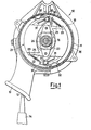
- Fig. 1 is a side view of the centrifugal brake form ing a part of a hauling device, partly in section.
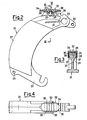
- Fig. 2 shows, on an enlarged scale, a side view of one of the shoes of the brake, with the applied gasket in section.
- Fig 3 is a sectional view along the line III-III of Fig. 2, and
- Fig. 4 is a partial view of the shoe along the arrow IV of Fig. 2.
- The hauling device, generally indicated as 10, com prises in a known manner a
casing 11 intended for being connected, e.g., fastened to a hauling cable (not shown) of a ski-lift plant. - The
casing 11 houses the recall device (not shown) for arope 12 which goes to the outside through a funnel-formlower orifice 13 of the casing, such rope bear ing at its free end ajoint 14 for the skier. - This recall device comprises in a known way a
drum 15 for winding therope 12, such drum being rotatably mounted on apivot 16 supported inside thecasing 11 and in a cover tightly applied on the casing, and defining a chamber which houses a recall spiral spring fixed at one of its ends to said cover, and at the other end at a hub coupled with saiddrum 15. This spiral spring tends to rotate thedrum 15 in the winding direction of the rope. - One side of the
winding drum 15 is provided on dia metrally opposed positions, with twoarticulation pins 20 for twoshoes 21 which have theiropposite end 22 hook . like shaped, and are loosely hooked to abrake guide 23 mounted on thehub 24 ofdrum 15. Springs 25 connect the twoshoes 21 to each other in order to holding them, un der static conditions, spaced apart from the insidecylindrical surface 26 of thecasing 11. - As is particularly evidenced in Figs. 2 - 4, each
shoe 21 consists of a shaped body moulded in one single piece from plastics, said body completely enclosing ametallic mass 27, which confers to the body itself the necessary weight for the centrifugal action. This shaped body moreover is already provided with all functional components, such as in particular thehook 22, athrough hole 28 suitable to house thearticulation pivot 20, as well asbores springs 25. It shall be noticed that thehole 28 for thepivot 20 communicates with aslit 31 which makes the same hole elastically en largeable and allows an elastically blocked coupling to be realized with thepin 20, thus securing a silent and smooth operating of the brake. - As the
metallic mass 27 is completely incorporated within the body of plastics of theshoe 21, it is as a result not only constrained to the body itself, but also protected from corrosion and oxydation. - The shoe of plastics bears moreover a
gasket 32, which, according to the invention, is mounted on the bo dy of the shoe itself so as to be able to slightly swing and to be easily replaced. In particular, thisgasket 32, which-is made from self lubricating plastic material, is provided on its rear side with twotransverse ribs 33 as a single piece, which define between each other a groove intended for being coupled with one from a series oftransverse teeth 35 peripherically protruding from the body of plastics of the shoe 21 (see Fig. 2). The coupling between the rear groove of thegasket 32 and thetooth 35 is such as to allow a limited swinging of the gasket around the slightly enlarged and rounded head of thetooth 35, so as to secure during the braking action the perfect fitting of the outside.surface of the gasket to the insidecylindrical surface 26 of thecasing 11. In such a way, not only a more uniform wear ofgasket 32 is obtained, but above all, thanks to the per feet fitting of the gasket to the inside surface of the casing, the forming is avoided of a hydrodynamic bearing between the braking surfaces, and the phenomenon of "aquaplaning" is avoided. - To this purpose helps the profile of the gasket too with its two opposite ends of
pointed shape 34 faced towards the turning directions of the shoe 21 (see Fig. 4) - The purpose of these sharp ends is of removing the liquid matter possibly penetrated inside the
casing 11. - The
gasket 32 is additionally provided with two flexible side fins of substantiallytriangular shape 36 with enlargedfree ends 37, whose purpose is of radial ly holding in position the gasket on the shoe, by acting in cooperation withside shoulders 38 of the shoe itself, without preventing said gaskets from swinging. - The
transverse teeth 35 are provided on the periphery of theshoe 21 in the nearby of its throughhole 28 suitable to house thearticulation pivot 20. The pres ence ofsuch teeth 35 makes it possible to move thegas ket 32 from tooth to tooth, thus allowing the braking force to be varied. Indeed, the closer the gasket is mounted to the shoe articulation axis, the larger is the braking force. - The assembling of the
gasket 32 onshoe 21 and hence the replacement of the gasket after its wearing down can be carried out with the highest.ease and rapidity. Indeed, slightly divaricating theflexible fins 36 of thegasket 32 is sufficient to the purpose of disengaging theirtips 37 from theside shoulders 38 of the shoe, and consequently of allowing the gasket to be radially removed. - The operating way of the centrifugal brake describe ed is not different to that of known brakes of this type and a detailed description of it is therefore not neces sary. The brake is active in both the turning directions of the
winding drum 15, that is to say, when therope 12 is being extracted from thecasing 11 and is unwound from the drum, as well as when therope 12, due to the action of the recall spring, is returned inside the cas ing, for being rewound on the drum. - By means of the new shaping of the brake shoes according to the present invention, many advantages are obtained, which can be clearly understood from the above set forth disclosure, and that are related to the manufacturing of the shoes, and to the assembling of them, as well as to their running and durability in time,. with out requiring frequent maintenance interventions. In par ticular, thanks to the perfect fitting of the gaskets to the sliding surfaces of the casing during the braking, guaranteed by the possibility of the gaskets to swing relatively to their respective shoes, it has been conclusively solved the problem of "aquaplaning" and the perfect operating of the brake has been guaranteed under all conditions, in addition rendering the wear of the gaskets more uniform.
Claims (5)
Priority Applications (1)
| Application Number | Priority Date | Filing Date | Title |
|---|---|---|---|
| AT84201262T ATE51594T1 (en) | 1983-09-16 | 1984-09-03 | PROGRESSIVE TRACTION DEVICE WITH CENTRIFUGAL BRAKE FOR SKI LIFTS. |
Applications Claiming Priority (2)
| Application Number | Priority Date | Filing Date | Title |
|---|---|---|---|
| ITMI1983U22994U IT8322994U1 (en) | 1983-09-16 | 1983-09-16 | CENTRIFUGAL BRAKE FOR PROGRESSIVE ACTION TOWING DEVICE FOR SKI LIFTS. |
| IT2299483U | 1983-09-16 |
Publications (3)
| Publication Number | Publication Date |
|---|---|
| EP0135239A2 true EP0135239A2 (en) | 1985-03-27 |
| EP0135239A3 EP0135239A3 (en) | 1986-12-03 |
| EP0135239B1 EP0135239B1 (en) | 1990-04-04 |
Family
ID=11202665
Family Applications (1)
| Application Number | Title | Priority Date | Filing Date |
|---|---|---|---|
| EP84201262A Expired - Lifetime EP0135239B1 (en) | 1983-09-16 | 1984-09-03 | Progressively acting hauling device for ski-lifts, with centrifugal brake |
Country Status (3)
| Country | Link |
|---|---|
| EP (1) | EP0135239B1 (en) |
| AT (1) | ATE51594T1 (en) |
| IT (1) | IT8322994U1 (en) |
Cited By (9)
| Publication number | Priority date | Publication date | Assignee | Title |
|---|---|---|---|---|
| US7891300B2 (en) | 2005-09-29 | 2011-02-22 | High Technology Investments B.V. | Cable derailing prevention device for carrier/traction cables of cable car systems |
| US8082853B2 (en) | 2003-01-30 | 2011-12-27 | High Technology Investments B.V. | Hold-down device for the cable guide in cable-drawn transport systems |
| US8393276B2 (en) | 2007-08-03 | 2013-03-12 | Rolic Invest S.Ar.L. | Cable transportation system and relative operating method |
| US8408141B2 (en) | 2007-10-26 | 2013-04-02 | Rolic Invest S.Ar.L. | Cable transportation system and relative operating method |
| US8474743B2 (en) | 2009-08-04 | 2013-07-02 | Rolic Invest S.Ar.L. | Ski-lift seat return device |
| US8573132B2 (en) | 2010-07-14 | 2013-11-05 | Rolic International S.Ar.L. | Cable transportation system switch and cable transportation system comprising such a switch |
| US8590458B2 (en) | 2007-04-20 | 2013-11-26 | Rolic Invest S.Ar.L. | Chair-lift |
| US8844446B2 (en) | 2007-04-20 | 2014-09-30 | Rolic International S.Ar.L. | Cable transportation system and relative drive method |
| US8991317B2 (en) | 2009-07-09 | 2015-03-31 | Rolic International S.A.R.L. | Transportation unit for cable transportation systems |
Family Cites Families (3)
| Publication number | Priority date | Publication date | Assignee | Title |
|---|---|---|---|---|
| CH259639A (en) * | 1947-12-03 | 1949-01-31 | Eisen Und Stahlwerke Oehler & | Tow brake for ski lift. |
| US3587474A (en) * | 1968-05-23 | 1971-06-28 | Roehrs Werner Dr Kg | Dragline winch for ski tows and the like |
| AT365132B (en) * | 1979-12-24 | 1981-12-10 | Doppelmayr & Sohn | IN- AND EXTENSION DEVICE FOR TOW ROPES OF TOW LIFTS |
-
1983
- 1983-09-16 IT ITMI1983U22994U patent/IT8322994U1/en unknown
-
1984
- 1984-09-03 EP EP84201262A patent/EP0135239B1/en not_active Expired - Lifetime
- 1984-09-03 AT AT84201262T patent/ATE51594T1/en not_active IP Right Cessation
Cited By (13)
| Publication number | Priority date | Publication date | Assignee | Title |
|---|---|---|---|---|
| US8082853B2 (en) | 2003-01-30 | 2011-12-27 | High Technology Investments B.V. | Hold-down device for the cable guide in cable-drawn transport systems |
| US7891300B2 (en) | 2005-09-29 | 2011-02-22 | High Technology Investments B.V. | Cable derailing prevention device for carrier/traction cables of cable car systems |
| US9463811B2 (en) | 2007-04-20 | 2016-10-11 | Ropfin B.V. | Cable transportation system and relative drive method |
| US8590458B2 (en) | 2007-04-20 | 2013-11-26 | Rolic Invest S.Ar.L. | Chair-lift |
| US8844446B2 (en) | 2007-04-20 | 2014-09-30 | Rolic International S.Ar.L. | Cable transportation system and relative drive method |
| US8393276B2 (en) | 2007-08-03 | 2013-03-12 | Rolic Invest S.Ar.L. | Cable transportation system and relative operating method |
| US8534196B2 (en) | 2007-08-03 | 2013-09-17 | Rolic Invest S.Ar.L | Cable transportation system and relative operating method |
| US9333876B2 (en) | 2007-08-03 | 2016-05-10 | Ropfin B.V. | Cable transportation system and relative operating method |
| US8408141B2 (en) | 2007-10-26 | 2013-04-02 | Rolic Invest S.Ar.L. | Cable transportation system and relative operating method |
| US8991317B2 (en) | 2009-07-09 | 2015-03-31 | Rolic International S.A.R.L. | Transportation unit for cable transportation systems |
| US9738290B2 (en) | 2009-07-09 | 2017-08-22 | Ropfin B.V. | Transportation unit for cable transportation systems |
| US8474743B2 (en) | 2009-08-04 | 2013-07-02 | Rolic Invest S.Ar.L. | Ski-lift seat return device |
| US8573132B2 (en) | 2010-07-14 | 2013-11-05 | Rolic International S.Ar.L. | Cable transportation system switch and cable transportation system comprising such a switch |
Also Published As
| Publication number | Publication date |
|---|---|
| EP0135239B1 (en) | 1990-04-04 |
| IT8322994U1 (en) | 1985-03-16 |
| EP0135239A3 (en) | 1986-12-03 |
| IT8322994V0 (en) | 1983-09-16 |
| ATE51594T1 (en) | 1990-04-15 |
Similar Documents
| Publication | Publication Date | Title |
|---|---|---|
| EP0135239A2 (en) | Progressively acting hauling device for ski-lifts, with centrifugal brake | |
| US4337851A (en) | Brake support assembly | |
| US4289217A (en) | Friction pad assemblies for disc brakes | |
| EP0928276A1 (en) | Idler roller | |
| US4441692A (en) | Rubber-lagged sheave | |
| US4230208A (en) | Moisture removal assembly | |
| JPH0233892B2 (en) | ||
| KR880005379A (en) | Pads for disc brakes and disc brakes equipped with such pads | |
| US5135181A (en) | Cable winder | |
| US4149336A (en) | Arrangement for detachable joint between a line and a snood | |
| US3920353A (en) | Impeller wheel for an axial flow fan with adjustable vanes | |
| JPS6224038A (en) | Brake pad assembly for disk brake | |
| KR960030780A (en) | Bait Throwing Fishing Reel | |
| US4278268A (en) | Ski brake | |
| US4036328A (en) | Disc brake apparatus suitable for bicycles | |
| CZ219799A3 (en) | Assembly Group | |
| FR2252507A1 (en) | Securing element for pressure roller in drum brake - comprises U-shaped bracket fixed to brake shoe by split pin | |
| US4374554A (en) | Duo-servo drum brake | |
| US4998602A (en) | Drum brake shoe hold-down and retraction spring and anchor post therefor | |
| US2939747A (en) | Tractor-track link pin and mounting unit | |
| DE2926885C2 (en) | ||
| US1938905A (en) | Brake seal | |
| US4157795A (en) | Fishing reel | |
| US1930417A (en) | Expanding brake | |
| US1943836A (en) | Brake operator |
Legal Events
| Date | Code | Title | Description |
|---|---|---|---|
| PUAI | Public reference made under article 153(3) epc to a published international application that has entered the european phase |
Free format text: ORIGINAL CODE: 0009012 |
|
| AK | Designated contracting states |
Designated state(s): AT CH FR LI SE |
|
| PUAL | Search report despatched |
Free format text: ORIGINAL CODE: 0009013 |
|
| RHK1 | Main classification (correction) |
Ipc: B61B 11/00 |
|
| AK | Designated contracting states |
Kind code of ref document: A3 Designated state(s): AT CH FR LI SE |
|
| 17P | Request for examination filed |
Effective date: 19870407 |
|
| 17Q | First examination report despatched |
Effective date: 19881004 |
|
| GRAA | (expected) grant |
Free format text: ORIGINAL CODE: 0009210 |
|
| AK | Designated contracting states |
Kind code of ref document: B1 Designated state(s): AT CH FR LI SE |
|
| REF | Corresponds to: |
Ref document number: 51594 Country of ref document: AT Date of ref document: 19900415 Kind code of ref document: T |
|
| ET | Fr: translation filed | ||
| PLBE | No opposition filed within time limit |
Free format text: ORIGINAL CODE: 0009261 |
|
| STAA | Information on the status of an ep patent application or granted ep patent |
Free format text: STATUS: NO OPPOSITION FILED WITHIN TIME LIMIT |
|
| 26N | No opposition filed | ||
| PGFP | Annual fee paid to national office [announced via postgrant information from national office to epo] |
Ref country code: SE Payment date: 19910813 Year of fee payment: 8 |
|
| PGFP | Annual fee paid to national office [announced via postgrant information from national office to epo] |
Ref country code: AT Payment date: 19910829 Year of fee payment: 8 |
|
| PGFP | Annual fee paid to national office [announced via postgrant information from national office to epo] |
Ref country code: FR Payment date: 19910902 Year of fee payment: 8 |
|
| PGFP | Annual fee paid to national office [announced via postgrant information from national office to epo] |
Ref country code: CH Payment date: 19910925 Year of fee payment: 8 |
|
| PG25 | Lapsed in a contracting state [announced via postgrant information from national office to epo] |
Ref country code: AT Effective date: 19920903 |
|
| PG25 | Lapsed in a contracting state [announced via postgrant information from national office to epo] |
Ref country code: SE Effective date: 19920904 |
|
| PG25 | Lapsed in a contracting state [announced via postgrant information from national office to epo] |
Ref country code: LI Effective date: 19920930 Ref country code: CH Effective date: 19920930 |
|
| PG25 | Lapsed in a contracting state [announced via postgrant information from national office to epo] |
Ref country code: FR Effective date: 19930528 |
|
| REG | Reference to a national code |
Ref country code: CH Ref legal event code: PL |
|
| REG | Reference to a national code |
Ref country code: FR Ref legal event code: ST |
|
| EUG | Se: european patent has lapsed |
Ref document number: 84201262.7 Effective date: 19930406 |