EP0135143B1 - Imaging method and apparatus using nuclear magnetic resonance - Google Patents
Imaging method and apparatus using nuclear magnetic resonance Download PDFInfo
- Publication number
- EP0135143B1 EP0135143B1 EP84109676A EP84109676A EP0135143B1 EP 0135143 B1 EP0135143 B1 EP 0135143B1 EP 84109676 A EP84109676 A EP 84109676A EP 84109676 A EP84109676 A EP 84109676A EP 0135143 B1 EP0135143 B1 EP 0135143B1
- Authority
- EP
- European Patent Office
- Prior art keywords
- nuclear
- spins
- magnetic resonance
- pulses
- imaging method
- Prior art date
- Legal status (The legal status is an assumption and is not a legal conclusion. Google has not performed a legal analysis and makes no representation as to the accuracy of the status listed.)
- Expired
Links
Images


Classifications
-
- G—PHYSICS
- G01—MEASURING; TESTING
- G01R—MEASURING ELECTRIC VARIABLES; MEASURING MAGNETIC VARIABLES
- G01R33/00—Arrangements or instruments for measuring magnetic variables
- G01R33/20—Arrangements or instruments for measuring magnetic variables involving magnetic resonance
- G01R33/44—Arrangements or instruments for measuring magnetic variables involving magnetic resonance using nuclear magnetic resonance [NMR]
- G01R33/48—NMR imaging systems
- G01R33/4818—MR characterised by data acquisition along a specific k-space trajectory or by the temporal order of k-space coverage, e.g. centric or segmented coverage of k-space
- G01R33/482—MR characterised by data acquisition along a specific k-space trajectory or by the temporal order of k-space coverage, e.g. centric or segmented coverage of k-space using a Cartesian trajectory
-
- G—PHYSICS
- G01—MEASURING; TESTING
- G01R—MEASURING ELECTRIC VARIABLES; MEASURING MAGNETIC VARIABLES
- G01R33/00—Arrangements or instruments for measuring magnetic variables
- G01R33/20—Arrangements or instruments for measuring magnetic variables involving magnetic resonance
- G01R33/44—Arrangements or instruments for measuring magnetic variables involving magnetic resonance using nuclear magnetic resonance [NMR]
- G01R33/48—NMR imaging systems
- G01R33/54—Signal processing systems, e.g. using pulse sequences ; Generation or control of pulse sequences; Operator console
- G01R33/56—Image enhancement or correction, e.g. subtraction or averaging techniques, e.g. improvement of signal-to-noise ratio and resolution
Definitions
- the present invention relates to an imaging method using nuclear magnetic resonance (which will be shortly referred to as "NMR") and, more particularly, to an imaging apparatus for imaging a nuclear density distribution or a relaxation time distribution by measuring the nuclear magnetic resonance signal of hydrogen or phosphor in an organism and an imaging method therefor.
- NMR nuclear magnetic resonance
- an X-ray CT or an ultrasonic imaging apparatus is widely used as an apparatus for imaging in vivo the internal structure such as the head or abdomen of a human body.
- the trial to make similar images by using the nuclear magnetic resonance phenomenon has succeeded so that the data which cannot be attained by the X-ray CT or the ultrasonic imaging apparatus can be achieved.
- the imaging apparatus using the nuclear magnetic resonance it is necessary to separate and discriminate the signal from an object to be imaged in a manner to correspond to the individual portions of the object.
- the direction of the gradient field is turned step by step, and the projection data of the resonance signals, which are obtained as functions of the intensities of the magnetic field for the respective angles of turns so that the images indicating the nuclear spin distribution of the object may be obtained.
- the distribution of the relaxation time may frequently become more important data than the distribution of the spin intensity.
- the absolute value of the relaxation time cannot be known from a single relaxation time enhanced image but can be determined either from both an intensity image indicating the intensity distribution of the nuclear spin and the relaxation time enhanced image or from a plurality of relaxation time enhanced images having different relaxation time effects.
- the imaging apparatus of the prior art has measured the intensity images and the relaxation time images, or the plural relaxation time enhanced images of different relaxation time effects independently of one another. As a result, the measurement time for obtaining those plural images has been the summation of the measurement times for obtaining the individual images.
- a first echo S1 which is free from the longitudinal relaxation effect, is detected at first. Then, after a period of t A from the first excitation of spins, the direction of the spins is inverted by a 180° RF pulse. After the period of T from the 180° RF pulse the spins are again excited to detect the second echo S2 which includes the effect of longitudinal relaxation. Since the method employs a 180° RF pulse in preparation of opposite-directed spins for the detection of the second echo S2, the 180° RF pulse should be applied when the spins have almost returned to the equilibrium state after the detection of the first echo S1. This means that the spins are submitted to spin-spin relaxation and spin- lattice relaxation which brings the spins almost into the equilibrium state.
- An object of the present invention is to provide an NMR imaging method and apparatus which can produce for a short time a plurality of images having different relaxation time effects, i.e., an intensity image and a relaxation time enhanced image, or a plurality of relaxation time enhanced images.
- the NMR imaging apparatus executes repeatedly a series of sequences, in which, after a first signal detecting step including excitation of the nuclear spin of an object to be imaged and detection of a resonance signal generated as a result of the excitation, a 90-degree RF magnetic field for rotating the direction of the nuclear spin oppositely of the initial state at the instant when the nuclear spins come into phase, and in which a second signal detecting step including again excitation of the nuclear spin and detection of a resonance signal generated as a result of the excitation is effected after that application.
- the imaging apparatus using the projection-reconstruction method it is the data of the object projected at a predetermined angle that are obtained by the above series sequences, and the imaging operations by the series sequences are repeated by varying the angles.
- the plural projection data of different relaxation time effects are obtained during the series sequences so that the number of repetitions of the imaging sequences is reduced, as compared with the prior art, to produce the plural images of different relaxation time effects for a substantially equal time.
- the imaging operation for the spin intensity image is conducted at the first signal detecting step, and the imaging operation for a longitudinal relaxation time enhanced image is conducted at the second signal detecting step.
- the present invention should not be limited to the above but can be applied to an apparatus for producing a plurality of various images having different effects of a longitudinal relaxation time T, and a transverse relaxation time T 2 .
- the direct Fourier imaging method or the projection-reconstruction method will produce a three-dimensional image if it is used of itself.
- FIG. 1 shows the construction of the imaging apparatus according to one embodiment of the present invention.
- a sequencer 4 outputs a variety of instructions at a predetermined timing to individual units.
- An RF-pulse generator 5 has its output amplified by an amplifier 6 to excite an RF coil 7.
- This RF coil 7 also acts as a receiving coil so that the signal component received is detected through an amplifier 8 by a phase sensitive detector 9 until it is transduced to an image by the action of a data processor 10.
- the output of the RF pulse generator 5 is used as a reference signal when a quadrature detection is conducted by the phase sensitive detector 9.
- the gradient fields in the direction A and in the perpendicular directions are generated by gradient coils 11, 12 and 13, respectively, which are driven by coil drivers 14, 15 and 16, respectively.
- the static field is generated by coils 17 which are driven by a current source 18.
- the gradient coil 13 has the same shape as that of the gradient coil 12 and a relation to the gradient coil 12 such that they are rotated at 90 degrees on the Z axis with respect to each other so that they generate the gradient fields perpendicular to each other.
- a human body, i.e., an object to be imaged is placed on a bed 20 which is carried on a carriage 21.
- the gradient field G x y is rotated step by step so that the projected data of the nuclear spin are obtained at each step.
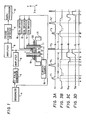
- Fig. 2 shows only a series of pulse sequences for obtaining projection data of a certain angle. In order to obtain a completed image, the sequences of Fig. 2 are repeated while the direction of the pulses G xy being rotated.
- the gradient field G z is applied. Substantially simultaneously with this, a 90-degree RF pulse magnetic field F 1 , which is the instant B as the center, is excited to rotate only the magnetization in a predetermined slice by 90 degrees.
- This 90-degree RF magnetic field has such a waveform, for example, as is modulated into a Gaussian type so that its band is restricted.
- the RF pulse magnetic field to be used with the application of that gradient field is called the "selective excitation pulses".
- the phase dispersion having occurred during the excitation of the 90-degree RF pulse magnetic field can be corrected by inverting the magnetic field G z at an instant C. More specifically, the waveform of the magnetic field G z is so set by the amplitude and application period of the current to be fed to the coil 11 as to satisfy the following equation:
- such a gradient field G xy is applied as has its direction changed on the xy-plane for each projection and its direction inverted at an intermediate instant H.
- the signal takes its peak at an instant E satisfying the following equation: If the gradient field G x y is promptly cut at the instant E, the nuclear spins thereafter can be brought into phase. In fact, however, the gradient field G x y drops with a predetermined time constant. After an instant F, therefore, the direction of the gradient field G XY is inverted. More specifically, the gradient field G xy is applied in a direction to delete the integrated value of the fall portion of the field G xy . The magnitude of this field G x y can be arbitrarily selected. As a result, the signal can be measured without being affected by the fall of the gradient field, and the magnetizations after the measurements can be brought into phase.
- the signal is taken in during the period DE because meaningful data are contained during that period.
- the signal during the period EG is not used for the image reconstruction because it is affected by the transient phenomena of the gradient field.
- the signal to be observed during the period DE contains data mainly concerning the intensity.
- the magnetization at the instant G is located in the xy-plane and is in phase so that a 90-degree RF pulse F 2 having no band restriction is excited.
- These magnetic pulses are called the "non-selective excitation pulses".
- the magnetization in a predetermined slice face is oriented in the opposite direction to that of the first magnetization because the 90-degree pulses are excited twice.
- the reason why the 90-degree pulses are made the non-selective excitation pulses is intended to make the period for application of the RF pulses as short as possible thereby to reduce the phase dispersion in the excitation period.
- a -90-degree selective excitation pulse F 3 is excited to turn the magnetization on the xy-plane. Then, the signal is measured like before during the period D'E'.
- the application sequences of the gradient fields front an instant A' to an instant G' are absolutely the same as the application sequences from the instant A to the instant G, as has been described hereinbefore. Only the difference from the period AG resides in that the selective excitation pulse F 3 is out of phase of 180 degrees from the pulse F 2 so that it is a -90- degree pulse.
- the projection data, on which the effects of the longitudinal relaxation time T, of the individual portions of the object are overlapped are detected.
- the magnetization of the object portion inverted at the instant G is designated at M(0)
- the magnetization of each portion after lapse of the period T is expressed by the following equation if the longitudinal relaxation time of that portion is designated at T l :
- the time ⁇ 1 can be arbitrarily selected in accordance with the enhancing effect of the period T i , normally, at 0.1 to 0.5 second, which range may be overpassed.
- the individual pulses for the period G'-G" are repetitions of the operations for the period G-G' so that the signals for various times T can be measured by those repetitions.
- F2' is another -90- degree pulse for non-selective excitation
- F3' is another -90-degree selective excitation pulse.
- the signals corresponding to 0.1, 0.2 and 0.3 second as the time T in the equation (4) are obtained.
- the period G-G' is usually 5 to 20 ms so that the measurement is ended for about 0.3 second so as to obtain four kinds of signals.
- the sequence of observing the projection data by a series of pulse applications is repeated while the direction of the pulses G xy being rotated step by step.
- the projection data for the period DE at each angle are reconstructed to produce the spin intensity image of the object.
- the projection data for the period D'E' or D"E" are reconstructed to produce a longitudinal relaxation time enhanced image.
- the total standby time for obtaining the signals of four kinds is 2 to 4 seconds. According to the present embodiment, the time period for the measurement is shortened several times, as compared with the prior art method.
- the reason why the 90-degree selective excitation pulse F 3 to be excited for the period GG' is out of phase by 180 degrees from the 90-degree pulse F, for the period AG is to make such signals of the same polarity as are generated by the respective pulse excitations.
- the phase of the pulse F 3 may be the same as that of the pulse F 1 .
- the signal observed in period D'E' should be inverted at the signal processing step.
- FIG. 3A shows RF pulses
- Fig. 3B shows the gradient field pulses G z in the z-direction
- Fig. 3C shows the gradient field pulses G xy in the x- and y-directions
- Fig. 3D shows an echo signal S d .
- the 180-degree selective excitation pulse F 4 is used for forming the echo signal. It is at an instant H, when a time t d equal to a time t d for the period BD elapses from the instant D, that the peak of the echo is formed. According to this method, the phase dispersion due to the uneveness of the static field can be corrected.
- the conditions for eliminating the phase dispersion by the pulses G x and G xy at the instant H and for forming the peak of the echo are given by the following equation:
- the sequences similar to those shown for the period A-I of Figs. 3A to 3D are repeated for the period A'-I'.
- F 4 ' is another 180-degree non-selective excitation pulse.
- the period A'-I' is different from the period A-I in that a standby has to be made for the time ⁇ 1 until the application of the pulse F 3 and in that the pulse F 3 is a -90-degree selective excitation pulses.
- the pulses for the period I-I' may be repeated again like Fig. 2.
- a plurality of projection data having different relaxation time effects can be obtained for the series sequences so that a plurality of images can be obtained for a short period by repeating the observations of the projection data to respectively reconstruct them while rotating the pulses G x y.
- it is also effective to invert and apply the gradient field G z for the time period matching the application of the magnetic field G z after the center of the 90-degree selective excitation pulse F, and to advance the instant F when the magnetic field G z is dropped after application of the 180-degree selective excitation pulse F 4 .
- Figs. 4A to 4C show a modified example of the pulse sequences of Figs. 2A to 2D.
- the pulses H 1 and Gx are common with those of the example of Fig. 2, but the pulses G XY shown in Fig. 4B have a different shape.
- the pulses G XY are inverted not at the instant E, when the signal S d shown in Fig. 4C takes its peak, but at the instant F' when the signal S d is attenuated again.
- the signals at both the sides of the peak can be used.
- the following condition is imposed to apply the 90-degree non-selective excitation pulses at the instant G when the phase dispersion is corrected:
- the non-selective RF excitation pulse F 2 is used to rotate the magnetization by 90 degrees
- the magnetization other than the predetermined slice face is also rotated by 90 degrees.
- this magnetization may possibly cause noises at the subsequent measurement.
- the magnetization other than the longitudinal one is attenuated by the pulses G z to be applied next so that the attenuation is effected to a sufficiently negligible value.
- a third embodiment is shown in Figs. 5A to 5D.
- the pulses G xy are applied for the period AB before the 180- degree selective excitation pulse magnetic field F 4 but are not inverted midway, as in the example shown in Figs. 3A to 3D.
- the signal takes its peak just at the instant D when the following equation is satisfied:
- the method of inverting the pulses G XY to eliminate the influences of the fall after the peak of the signal not only the method shown in Figs. 2 and 3 but also the method shown in Fig. 4 can be used together, as in the embodiment of Fig. 3.
- FIG. 6A to 6D A fourth embodiment of the present invention is shown in Figs. 6A to 6D.
- the RF selective excitation pulse is used for the 90-degree pulses after the end of observation for obtaining the intensity image so that measurement can be made without giving any disturbance to the region other than the object slice.
- the condition for bringing the echos into phase at the instant B thereby to cause the peak is given by the following equation: After the appearance of the peak of that signal, the pulses G xy are inverted so as to eliminate the influences of the fall.
- the peak of the signal appears again at the instant C where the following condition is satisfied: If the 90-degree RF selective excitation pulse is applied at the instant when the signals are in phase, the magnetization in the slice is rotated by 90 degrees until it is oriented in the direction of -Z. The reason why the gradient field pulses G z in the -Z direction are applied at the instant B is to remove the phase dispersion which is caused during the excitation of the selective excitation pulse and the gradient field pulses are applied in a manner to substantially satisfy the following equation:
- the phase dispersion generated as a result of unevenness of the static field like the example shown in Figs. 2A to 2D is not corrected, but the error may be accumulated each time the sequence of the period AD is repeated.
- the 180-degree pulses may be excited midway to correct the phase dispersion resulting from the unevenness of the static field.
- the signals can be brought into phase by using not only the sequences shown in Figs.
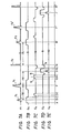
- Fig. 7A shows RF magnetic field pulses H l ;
- Fig. 7B shows gradient field pulses G z in the z direction;
- Fig. 7C shows gradient field pulses Gx in the x direction;
- Fig. 7D shows gradient field pulses Gy in the y-direction; and
- Fig. 7E shows an echo signal.
- the 90-degree selective excitation pulse F 1 is applied with the application of the pulse G z to excite the magnetization of a predetermined slice face.
- the 180-degree selective excitation pulse F 4 are applied so that the spin echo may be generated in the signal Sg at an instant J after lapse of a time t d .
- the signal Sg has its phase encoded in accordance with the amplitude of the pulses G x applied for the period GI. More specifically, the integrated value of the remaining portion b, which is the remainder of the subtraction of the portion matching the pulses applied in advance for the period DE before the 180-degree selective excitation pulse F 4 is applied, provides the magnitude of the phase encoding.
- the y-direction gradient field Gy which is inverted midway from the instant I, is applied.
- the signal around the instant J provides the data containing the spin intensity distribution.
- the pulse Gy is inverted.
- the pulse G x in the opposite direction for matching the portion b is applied so that the direction of the magnetization may be aligned at an instant M.
- the conditions for this alignment are to satisfy the following two equations:
- the -90-degree non-selective excitation pulse F s is applied.
- the magnetization in the predetermined slice face is resultantly rotated by 180 degrees from the initial state to the -z direction.
- F 4 ' is another 180-degree selective excitation pulse.
- the pulse F 3 is applied at an instant B, after lapse of the time Ti from the instant M so as to effect the longitudinal relaxation time.
- the pulse F 3 is different from the pulse F, in that it is a -90-degree selective excitation pulse selective excitation pulse.
- the signal S d observed around the instant J' contains the data of the intensity distribution on which the effects of the longitudinal relaxation time after lapse of the time T1 are overlapped. By repeating the sequences for the period M-M', it is possible to obtain other data on which the effects after lapse of the time of 2i i .
- the series pulse sequences thus far described are repeatedly executed several times by varying the amplitude of the phase encoding pulses G x step by step.
- the data observed around the instants J and J' are accumulated and are subjected to two-dimensional Fourier inverse transformation so that the intensity images and the T, enhanced images are produced.
- the present invention can also be applied to the case in which the direct Fourier imaging method is used as above.
- the present invention should not be limited to Figs. 7A to 7E, but the spin echo can be formed by the use of inversion of the pulses G x in place of the 180- degree selective excitation pulses, as in the example shown in Figs. 2A to 2D.
- the pulse Gy is inverted, and the observation of the data may be limited to before the instant J (or J').
- all the RF magnetic field pulses can be selective excitation pulses.
- the 180-degree selective excitation pulses are used to form the spin echo. It should be also understood that such spin echo may be formed by the application of the 180-degree non-selective excitation pulses with no application of the pulses G z . Further it should be noted that the pulses to rotate the magnetization for -90 degrees may be the non-selective excitation pulses (with no application of the pulse G 2 ) other than the non-selective excitation pulses.
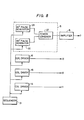
- Fig. 8 is a block diagram for realizing the individual embodiments thus far described.
- reference numerals 29 and 30 indicate a 90-degree pulse generator and a 180- degree pulse generator, both of which are connected with a power combiner 27. These pulse generators 29 and 30 and power combiner 27 construct together the pulse generator 5 of Fig. 1. Moreover, all the X-, Y- and Z-gradient field generators and the 90- and 180-degree pulse generators are controlled by a sequencer 31.
- This sequencer 31 forms a part of the sequencer 4 of Fig. 1 and is constructed such that it can generate the timing signal for the sequences of the foregoing individual examples thereby to control the signals of the individual pulse generators. This operation can be achieved, as a specific example, by storing the sequence in an ROM.
- the same numerals indicate portions identical to those of Fig. 1.
- both the waveform and square form, to which the amplitudes are modulated by the Gaussian or Sinc Function, are used as the pulses for generating the RF magnetic fields.
- the latter has to have a large amplitude so as to shorten the excitation period and is accordingly formed into the square shape which can be easily modulated.
- the amplifiers which are featured by not efficiency but linear relationship such as A-class or AB-class amplifiers having a linear relationship in its input/ output characteristics are suitable.
- a C-class or amplifier having an excellent efficiency or an AB-class amplifier of less idling current in its operation is suitable because the latter may use square waves.
- the AB-class amplifier can be used for the former or latter because it can change its efficiency by changing the idling current. Therefore, the apparatus making use of two kinds of amplifiers having different efficiencies and used in the amplifier of Fig. 1 is shown in Fig. 9.
- An RF input In is divided by the action of a divider 22 into two halves, which are inputted through gates 23 and 24 to amplifiers 25 and 26.
- the operations of the gates are shown in Figs. 10A to 1 OC.
- the gate 23 shown in Fig. 10B is turned on so that the input is applied to the amplifier 25.
- the gate 23 is turned off so that no input is applied to the amplifier 25.
- the other gate 24 conducts the opposite operation, as shown in Fig. 10C.
- the amplifier 25 is the A- or AB-class highly linear amplifiers, whereas the amplifier 26 is the AB- or C-class highly efficient amplifier.
- the outputs of the amplifiers 25 and 26 are composed by a combiner 27 until they are inputted to the RF magnetic field generating coil 7.
Description
- The present invention relates to an imaging method using nuclear magnetic resonance (which will be shortly referred to as "NMR") and, more particularly, to an imaging apparatus for imaging a nuclear density distribution or a relaxation time distribution by measuring the nuclear magnetic resonance signal of hydrogen or phosphor in an organism and an imaging method therefor.
- In the prior art, an X-ray CT or an ultrasonic imaging apparatus is widely used as an apparatus for imaging in vivo the internal structure such as the head or abdomen of a human body. In recent years, it has been revealed that the trial to make similar images by using the nuclear magnetic resonance phenomenon has succeeded so that the data which cannot be attained by the X-ray CT or the ultrasonic imaging apparatus can be achieved. In the imaging apparatus using the nuclear magnetic resonance, it is necessary to separate and discriminate the signal from an object to be imaged in a manner to correspond to the individual portions of the object. There is one method for obtaining positional data of an object to be detected by applying a gradient field to the object to make different the static fields, in which the portions of the object are placed, thereby to make different the resonance frequencies of the individual portions. For example, in an imaging method called the "projection-reconstruction method", which is disclosed by C-M Lai and P. C. Lauterbur, Journal of Physics (E) Scientific Instrument Vol. 13, 1980, pp 747-750, the direction of the gradient field is turned step by step, and the projection data of the resonance signals, which are obtained as functions of the intensities of the magnetic field for the respective angles of turns so that the images indicating the nuclear spin distribution of the object may be obtained.
- As is disclosed by J. M. S. Hutchison, et al., Journal of Physics (E) Scientific Instrument Vol. 13, 1980 pp 947-955, the difference in longitudinal relaxation time at the individual portions of the object appears in a superposed manner on the spin intensity distribution if RF magnetic pulses for rotating the nuclear spin 180 degrees are applied prior to the measurement of the individual projection data and if the nuclear spin is excited again after a predetermined time has elapsed. This image will be called a "relaxation time enhanced image" in the following.
- The distribution of the relaxation time may frequently become more important data than the distribution of the spin intensity. However, the absolute value of the relaxation time cannot be known from a single relaxation time enhanced image but can be determined either from both an intensity image indicating the intensity distribution of the nuclear spin and the relaxation time enhanced image or from a plurality of relaxation time enhanced images having different relaxation time effects. Despite of this fact, the imaging apparatus of the prior art has measured the intensity images and the relaxation time images, or the plural relaxation time enhanced images of different relaxation time effects independently of one another. As a result, the measurement time for obtaining those plural images has been the summation of the measurement times for obtaining the individual images.
- From "Physics in Medicine and Biology", Vol. 28, June 1983, No. 6, pages 723 to 729 there is known an imaging message for obtaining a plurality of images having different longitudinal relaxation effects. For detecting an echo including the effect of longitudinal relaxation between a term "T" (T1-enhanced echo) it is necessary to invert the direction of spins to the direction opposite to that of an equilibrium state before exciting the spins, i.e. the step of preparing opposite-directed spins.
- According to this reference, a first echo S1, which is free from the longitudinal relaxation effect, is detected at first. Then, after a period of tA from the first excitation of spins, the direction of the spins is inverted by a 180° RF pulse. After the period of T from the 180° RF pulse the spins are again excited to detect the second echo S2 which includes the effect of longitudinal relaxation. Since the method employs a 180° RF pulse in preparation of opposite-directed spins for the detection of the second echo S2, the 180° RF pulse should be applied when the spins have almost returned to the equilibrium state after the detection of the first echo S1. This means that the spins are submitted to spin-spin relaxation and spin- lattice relaxation which brings the spins almost into the equilibrium state. This is the reason, why there is a certain waiting period oftA between the detection of the first echo and the detection of the second echo. Thus, the spins are not in phase when they are to be rotated to the direction opposite to that of an equilibrium state. It is true that the spins are almost directed to that direction. However, the transverse components of magnetization of respective spins slightly remain and are not in phase.
- An object of the present invention is to provide an NMR imaging method and apparatus which can produce for a short time a plurality of images having different relaxation time effects, i.e., an intensity image and a relaxation time enhanced image, or a plurality of relaxation time enhanced images.
- The NMR imaging apparatus according to a feature of the present invention executes repeatedly a series of sequences, in which, after a first signal detecting step including excitation of the nuclear spin of an object to be imaged and detection of a resonance signal generated as a result of the excitation, a 90-degree RF magnetic field for rotating the direction of the nuclear spin oppositely of the initial state at the instant when the nuclear spins come into phase, and in which a second signal detecting step including again excitation of the nuclear spin and detection of a resonance signal generated as a result of the excitation is effected after that application.
- By varying the standby time until the excitation of the nuclear spin at said first signal detecting step and said second signal detecting step, there are obtained resonance signal data which have different effects of the relaxation time.
- In the imaging apparatus using the projection-reconstruction method, it is the data of the object projected at a predetermined angle that are obtained by the above series sequences, and the imaging operations by the series sequences are repeated by varying the angles. According to the present invention, the plural projection data of different relaxation time effects are obtained during the series sequences so that the number of repetitions of the imaging sequences is reduced, as compared with the prior art, to produce the plural images of different relaxation time effects for a substantially equal time.
- Incidentally, in a typical example, the imaging operation for the spin intensity image is conducted at the first signal detecting step, and the imaging operation for a longitudinal relaxation time enhanced image is conducted at the second signal detecting step. However, the present invention should not be limited to the above but can be applied to an apparatus for producing a plurality of various images having different effects of a longitudinal relaxation time T, and a transverse relaxation time T2.
- There have been proposed a variety of methods of directly imaging Fourier-transformed orthogonal coordinate points of the nuclear spin distribution or the relaxation time distribution in an object be imaged, as is different from the projection-reconstruction method. In the apparatus using this direct Fourier imaging method, too, a plurality of imaging operations by repeating the predetermined pulse sequences are required for obtaining completed image data. By applying the present invention, the plural data of different relaxation time effects can be imaged during a series of pulse sequences repeated plural times so that the plural images such as the intensity images or the relaxation time enhanced images can be produced for a period substantially equal to that for producing a single image.
- Moreover, the direct Fourier imaging method or the projection-reconstruction method will produce a three-dimensional image if it is used of itself. Despite of this, most of the actual apparatus imaging a predetermined slice face of the object by the method called the "selective excitation method". The specific explanation of the present invention to be made hereinafter is concerned with the latter example, but the present invention can be applied to the former example.
-
- Fig. 1 is a diagram showing the construction of one embodiment of the apparatus to be used in the present invention;
- Figs. 2, 3, 4, 5, 6 and 7 are charts for explaining the embodiments of the pulse sequences to be used in the present invention;
- Fig. 8 is a block diagram showing the construction of one embodiment of the present invention for the pulse sequences;
- Fig. 9 is a diagram showing an example of the construction which uses two kinds of amplifiers having different efficiencies; and
- Fig. 10 is a time chart showing the operations of Fig. 9.
- The present invention will be described in the following in connection with the embodiments thereof with reference to the accompanying drawings. Fig. 1 shows the construction of the imaging apparatus according to one embodiment of the present invention. A sequencer 4 outputs a variety of instructions at a predetermined timing to individual units. An RF-
pulse generator 5 has its output amplified by anamplifier 6 to excite anRF coil 7. ThisRF coil 7 also acts as a receiving coil so that the signal component received is detected through anamplifier 8 by a phasesensitive detector 9 until it is transduced to an image by the action of adata processor 10. The output of theRF pulse generator 5 is used as a reference signal when a quadrature detection is conducted by the phasesensitive detector 9. The gradient fields in the direction A and in the perpendicular directions are generated bygradient coils coil drivers coils 17 which are driven by acurrent source 18. Thegradient coil 13 has the same shape as that of thegradient coil 12 and a relation to thegradient coil 12 such that they are rotated at 90 degrees on the Z axis with respect to each other so that they generate the gradient fields perpendicular to each other. A human body, i.e., an object to be imaged is placed on abed 20 which is carried on acarriage 21. - Figs. 2A to 2D show examples of the pulse sequences of the present embodiment. These examples are prepared by the projection-reconstruction method, and a similar method can also be applied to the Fourier zeugmatography, the spin warp imaging method and so on.
- Fig. 2A shows the RF pulses H, which are generated by the
RF coil 7. Incidentally, it is only one side of the envelope that is shown. Fig. 2B shows the gradient field pulses Gz in the direction of the Z axis, which are generated by thegradient coil 11. Fig. 2C shows the gradient field pulses GXY which are generated perpendicularly to the pulses Gz by the gradient coils 12 and 13. - Fig. 2D shows one side of the envelope of the echo signal which is observed by the
RF coil 7. Here, the gate disposed in the receiving system is turned off during the period except the periods D-G, D'-G' and D"-G" so that the signal is not used as the data. - In the projection-reconstruction method, the gradient field Gxy is rotated step by step so that the projected data of the nuclear spin are obtained at each step. Fig. 2 shows only a series of pulse sequences for obtaining projection data of a certain angle. In order to obtain a completed image, the sequences of Fig. 2 are repeated while the direction of the pulses Gxy being rotated. First of all, at an instant A, the gradient field Gz is applied. Substantially simultaneously with this, a 90-degree RF pulse magnetic field F1, which is the instant B as the center, is excited to rotate only the magnetization in a predetermined slice by 90 degrees. This 90-degree RF magnetic field has such a waveform, for example, as is modulated into a Gaussian type so that its band is restricted. The RF pulse magnetic field to be used with the application of that gradient field is called the "selective excitation pulses". The phase dispersion having occurred during the excitation of the 90-degree RF pulse magnetic field can be corrected by inverting the magnetic field Gz at an instant C. More specifically, the waveform of the magnetic field Gz is so set by the amplitude and application period of the current to be fed to the
coil 11 as to satisfy the following equation:
- At an instant C, moreover, such a gradient field Gxy is applied as has its direction changed on the xy-plane for each projection and its direction inverted at an intermediate instant H. At this time, the signal takes its peak at an instant E satisfying the following equation:

- In this case, the following equation holds:

- The signal is taken in during the period DE because meaningful data are contained during that period. However, the signal during the period EG is not used for the image reconstruction because it is affected by the transient phenomena of the gradient field. The signal to be observed during the period DE contains data mainly concerning the intensity.
- Now, the magnetization at the instant G is located in the xy-plane and is in phase so that a 90-degree RF pulse F2 having no band restriction is excited. These magnetic pulses are called the "non-selective excitation pulses". The magnetization in a predetermined slice face is oriented in the opposite direction to that of the first magnetization because the 90-degree pulses are excited twice. The reason why the 90-degree pulses are made the non-selective excitation pulses is intended to make the period for application of the RF pulses as short as possible thereby to reduce the phase dispersion in the excitation period.
- When a period τ1 elapses after excitation of the 90-degree non-selective excitation pulse F2, a -90-degree selective excitation pulse F3 is excited to turn the magnetization on the xy-plane. Then, the signal is measured like before during the period D'E'. The application sequences of the gradient fields front an instant A' to an instant G' are absolutely the same as the application sequences from the instant A to the instant G, as has been described hereinbefore. Only the difference from the period AG resides in that the selective excitation pulse F3 is out of phase of 180 degrees from the pulse F2 so that it is a -90- degree pulse. During this period D'E', the projection data, on which the effects of the longitudinal relaxation time T, of the individual portions of the object are overlapped, are detected. If the magnetization of the object portion inverted at the instant G is designated at M(0), the magnetization of each portion after lapse of the period T is expressed by the following equation if the longitudinal relaxation time of that portion is designated at Tl:

- Incidentally, the reason why the 90-degree selective excitation pulse F3 to be excited for the period GG' is out of phase by 180 degrees from the 90-degree pulse F, for the period AG is to make such signals of the same polarity as are generated by the respective pulse excitations. However, the phase of the pulse F3 may be the same as that of the pulse F1. In this case, the signal observed in period D'E' should be inverted at the signal processing step.
- A second embodiment of the present invention is shown in Fig. 3A to 3D. Specifically: Fig. 3A shows RF pulses; Fig. 3B shows the gradient field pulses Gz in the z-direction; Fig. 3C shows the gradient field pulses Gxy in the x- and y-directions; and Fig. 3D shows an echo signal Sd.
- In this embodiment, not the inversion of the gradient field Gz but the 180-degree selective excitation pulse F4 is used for forming the echo signal. It is at an instant H, when a time td equal to a time td for the period BD elapses from the instant D, that the peak of the echo is formed. According to this method, the phase dispersion due to the uneveness of the static field can be corrected. The conditions for eliminating the phase dispersion by the pulses Gx and Gxy at the instant H and for forming the peak of the echo are given by the following equation:

- In order to be freed from the fall of the pulses Gxy and to bring the pulses into phase at the instant I, on the other hand, the following equation has to hold:

- By the sequences of Figs. 3A to 3D, too, as has been described hereinbefore, a plurality of projection data having different relaxation time effects can be obtained for the series sequences so that a plurality of images can be obtained for a short period by repeating the observations of the projection data to respectively reconstruct them while rotating the pulses Gxy. As shown by broken lines in Fig. 3B, incidentally, it is also effective to invert and apply the gradient field Gz for the time period matching the application of the magnetic field Gz after the center of the 90-degree selective excitation pulse F, and to advance the instant F when the magnetic field Gz is dropped after application of the 180-degree selective excitation pulse F4.
- Figs. 4A to 4C show a modified example of the pulse sequences of Figs. 2A to 2D. In this modified example, the pulses H1 and Gx are common with those of the example of Fig. 2, but the pulses GXY shown in Fig. 4B have a different shape. Specif- cally, the pulses GXY are inverted not at the instant E, when the signal Sd shown in Fig. 4C takes its peak, but at the instant F' when the signal Sdis attenuated again. As a result, the signals at both the sides of the peak can be used. In this case, too, the following condition is imposed to apply the 90-degree non-selective excitation pulses at the instant G when the phase dispersion is corrected:
-

- This modification can also be made to the embodiment shown in Fig. 3.
- Since, in the examples thus far described, the non-selective RF excitation pulse F2 is used to rotate the magnetization by 90 degrees, the magnetization other than the predetermined slice face is also rotated by 90 degrees. As a result, this magnetization may possibly cause noises at the subsequent measurement. In fact, however, the magnetization other than the longitudinal one is attenuated by the pulses Gz to be applied next so that the attenuation is effected to a sufficiently negligible value.
- Moreover, a third embodiment is shown in Figs. 5A to 5D. In the present embodiment, the pulses Gxy are applied for the period AB before the 180- degree selective excitation pulse magnetic field F4 but are not inverted midway, as in the example shown in Figs. 3A to 3D. The signal takes its peak just at the instant D when the following equation is satisfied:

- A fourth embodiment of the present invention is shown in Figs. 6A to 6D. Here, the RF selective excitation pulse is used for the 90-degree pulses


- Thus, by repeating the period AD after the standby time of τ1 after the magnetization is inverted in the direction of just 180 degrees from the first, it is possible to obtain signals for a variety of longitudinal relaxation times. In the method shown in Figs. 6A to 6D, the phase dispersion generated as a result of unevenness of the static field like the example shown in Figs. 2A to 2D is not corrected, but the error may be accumulated each time the sequence of the period AD is repeated. As shown in Figs. 3A to 3D, on the contrary, the 180-degree pulses may be excited midway to correct the phase dispersion resulting from the unevenness of the static field. Incidentally, the signals can be brought into phase by using not only the sequences shown in Figs. 6A to 6D but also the sequences shown in the embodiments thus far described so that the pulses Gz shown in Fig. 6B and the 90-degree selective excitation pulses F2' shown in Fig. 6A can be applied at that instant. On the other hand, the description thus far described is directed to the intensity image and the longitudinal relaxation time enhanced image. By changing the time td shown in Fig. 3B, however, the transverse relaxation time enhanced image can also be produced. In this case, it is necessary to measure the transverse relaxation time enhanced image after the intensity image has been measured.
- The pulse sequences according to the fifth embodiment of the present invention are shown in Figs. 7A to 7E. Fig. 7A shows RF magnetic field pulses Hl; Fig. 7B shows gradient field pulses Gz in the z direction; Fig. 7C shows gradient field pulses Gx in the x direction; Fig. 7D shows gradient field pulses Gy in the y-direction; and Fig. 7E shows an echo signal.
- These sequences are used in case the images are to be constructed by the Fourier zeugmatography. In the projection-reconstruction method shown in Fig. 2 to 6, gradient fields Gx and Gy are applied at the same time. In the present sequences, however, positional data are given two-dimensionally to the object by giving the phase in the x-direction with the pulses Gx and then by giving the phase in the y-direction with the pulses Gy so that the original object may be reproduced by the Fourier transformation of the signals obtained.
- First of all, at the instant B, the 90-degree selective excitation pulse F1 is applied with the application of the pulse Gz to excite the magnetization of a predetermined slice face. After lapse of the time Td from that instant, the 180-degree selective excitation pulse F4 are applied so that the spin echo may be generated in the signal Sg at an instant J after lapse of a time td. Here, the signal Sg has its phase encoded in accordance with the amplitude of the pulses Gx applied for the period GI. More specifically, the integrated value of the remaining portion b, which is the remainder of the subtraction of the portion matching the pulses applied in advance for the period DE before the 180-degree selective excitation pulse F4 is applied, provides the magnitude of the phase encoding. In order to give the data in the y-direction, on the other hand, the y-direction gradient field Gy, which is inverted midway from the instant I, is applied. At the instant J when the spin echo reaches its peak, the following equation holds:

- The signal around the instant J provides the data containing the spin intensity distribution. At an instant K after observation of the data, the pulse Gy is inverted. At an instant L, moreover, the pulse Gx in the opposite direction for matching the portion b is applied so that the direction of the magnetization may be aligned at an instant M. The conditions for this alignment are to satisfy the following two equations:
-

- Thus, atthe instant M when the magnetizations in the predetermined slice face are aligned, the -90-degree non-selective excitation pulse Fs is applied. Thus, by summing up the selective excitation pulses F, and F4 applied in advance, the magnetization in the predetermined slice face is resultantly rotated by 180 degrees from the initial state to the -z direction. After the instant M, the sequences described above are repeated to obtain the data on which the effects of the longitudinal relaxation time are overlapped. Namely, F4' is another 180-degree selective excitation pulse. Despite of this fact, the pulse F3 is applied at an instant B, after lapse of the time Ti from the instant M so as to effect the longitudinal relaxation time. Incidentally, the pulse F3 is different from the pulse F, in that it is a -90-degree selective excitation pulse selective excitation pulse. The signal Sd observed around the instant J' contains the data of the intensity distribution on which the effects of the longitudinal relaxation time after lapse of the time T1 are overlapped. By repeating the sequences for the period M-M', it is possible to obtain other data on which the effects after lapse of the time of 2ii.
- The series pulse sequences thus far described are repeatedly executed several times by varying the amplitude of the phase encoding pulses Gx step by step. The data observed around the instants J and J' are accumulated and are subjected to two-dimensional Fourier inverse transformation so that the intensity images and the T, enhanced images are produced.
- The present invention can also be applied to the case in which the direct Fourier imaging method is used as above. Despite of this fact, the present invention should not be limited to Figs. 7A to 7E, but the spin echo can be formed by the use of inversion of the pulses Gx in place of the 180- degree selective excitation pulses, as in the example shown in Figs. 2A to 2D. At the instant J (or J') of the peak of the spin echo, moreover, the pulse Gy is inverted, and the observation of the data may be limited to before the instant J (or J'). Like the example shown in Fig. 6, still moreover, all the RF magnetic field pulses can be selective excitation pulses.
- As shown in Figs. 3, 5, and 7, the 180-degree selective excitation pulses are used to form the spin echo. It should be also understood that such spin echo may be formed by the application of the 180-degree non-selective excitation pulses with no application of the pulses Gz. Further it should be noted that the pulses to rotate the magnetization for -90 degrees may be the non-selective excitation pulses (with no application of the pulse G2) other than the non-selective excitation pulses.
- Fig. 8 is a block diagram for realizing the individual embodiments thus far described.
- In the Figure,
reference numerals power combiner 27. Thesepulse generators power combiner 27 construct together thepulse generator 5 of Fig. 1. Moreover, all the X-, Y- and Z-gradient field generators and the 90- and 180-degree pulse generators are controlled by asequencer 31. Thissequencer 31 forms a part of the sequencer 4 of Fig. 1 and is constructed such that it can generate the timing signal for the sequences of the foregoing individual examples thereby to control the signals of the individual pulse generators. This operation can be achieved, as a specific example, by storing the sequence in an ROM. In Fig. 8, incidentally, the same numerals indicate portions identical to those of Fig. 1. - In the description thus far made, both the waveform and square form, to which the amplitudes are modulated by the Gaussian or Sinc Function, are used as the pulses for generating the RF magnetic fields. The latter has to have a large amplitude so as to shorten the excitation period and is accordingly formed into the square shape which can be easily modulated.
- As a result, it becomes remarkably inefficient to generate the waveforms of the two by the single amplifier. For the former, more specifically, the amplifiers which are featured by not efficiency but linear relationship, such as A-class or AB-class amplifiers having a linear relationship in its input/ output characteristics are suitable. For the latter, on the other hand, a C-class or amplifier having an excellent efficiency or an AB-class amplifier of less idling current in its operation is suitable because the latter may use square waves.
- Incidentally, the AB-class amplifier can be used for the former or latter because it can change its efficiency by changing the idling current. Therefore, the apparatus making use of two kinds of amplifiers having different efficiencies and used in the amplifier of Fig. 1 is shown in Fig. 9. An RF input In is divided by the action of a
divider 22 into two halves, which are inputted throughgates amplifiers gate 23 shown in Fig. 10B is turned on so that the input is applied to theamplifier 25. For the -90-degree non-selective excitation pulse Fs, on the other hand, thegate 23 is turned off so that no input is applied to theamplifier 25. Theother gate 24 conducts the opposite operation, as shown in Fig. 10C. Theamplifier 25 is the A- or AB-class highly linear amplifiers, whereas theamplifier 26 is the AB- or C-class highly efficient amplifier. The outputs of theamplifiers combiner 27 until they are inputted to the RF magneticfield generating coil 7.
Claims (10)
Applications Claiming Priority (2)
| Application Number | Priority Date | Filing Date | Title |
|---|---|---|---|
| JP148081/83 | 1983-08-15 | ||
| JP58148081A JPS6039539A (en) | 1983-08-15 | 1983-08-15 | Inspecting device using nuclear magnetic resonance |
Publications (3)
| Publication Number | Publication Date |
|---|---|
| EP0135143A2 EP0135143A2 (en) | 1985-03-27 |
| EP0135143A3 EP0135143A3 (en) | 1986-07-09 |
| EP0135143B1 true EP0135143B1 (en) | 1990-10-31 |
Family
ID=15444800
Family Applications (1)
| Application Number | Title | Priority Date | Filing Date |
|---|---|---|---|
| EP84109676A Expired EP0135143B1 (en) | 1983-08-15 | 1984-08-14 | Imaging method and apparatus using nuclear magnetic resonance |
Country Status (5)
| Country | Link |
|---|---|
| US (1) | US4683433A (en) |
| EP (1) | EP0135143B1 (en) |
| JP (1) | JPS6039539A (en) |
| CA (1) | CA1233201A (en) |
| DE (1) | DE3483502D1 (en) |
Families Citing this family (7)
| Publication number | Priority date | Publication date | Assignee | Title |
|---|---|---|---|---|
| DE3445689A1 (en) * | 1984-12-14 | 1986-06-19 | Max-Planck-Gesellschaft zur Förderung der Wissenschaften e.V., 3400 Göttingen | METHOD AND DEVICE FOR SPOTLESS EXAMINATION OF A SAMPLE BY MEANS OF MAGNETIC RESONANCE OF SPIN MOMENTS |
| JPS61239150A (en) * | 1985-04-16 | 1986-10-24 | Yokogawa Electric Corp | Nuclear magnetic resonance image pickup device |
| US4761613A (en) * | 1987-08-12 | 1988-08-02 | Picker International, Inc. | Monitored echo gating for the reduction of motion artifacts |
| GB8819753D0 (en) * | 1988-08-19 | 1988-09-21 | Nycomed As | Apparatus |
| JPH0263435A (en) * | 1988-08-31 | 1990-03-02 | Toshiba Corp | Magnetic resonance imaging method |
| GB9200606D0 (en) * | 1992-01-13 | 1992-03-11 | British Tech Group | Method of and apparatus for obtaining spatial nmr information |
| US7176687B2 (en) * | 2002-04-16 | 2007-02-13 | Koninklijke Philips Electronics N.V. | T1-weighted multiecho magnetic resonance imaging |
Family Cites Families (7)
| Publication number | Priority date | Publication date | Assignee | Title |
|---|---|---|---|---|
| CA1147806A (en) * | 1980-03-14 | 1983-06-07 | William A. Edelstein | Methods of producing image information from objects |
| US4383219A (en) * | 1980-08-19 | 1983-05-10 | Indiana University Foundation | Nuclear magnetic resonance spatial mapping |
| US4471306A (en) * | 1982-02-03 | 1984-09-11 | General Electric Company | Method of NMR imaging which overcomes T2 * effects in an inhomogeneous static magnetic field |
| GB2125559B (en) * | 1982-08-11 | 1986-02-05 | Picker Int Ltd | Nuclear magnetic resonance method and apparatus |
| GB2125562B (en) * | 1982-08-19 | 1985-11-20 | Picker Int Ltd | Nuclear magnetic resonance methods and apparatus |
| JPS5946546A (en) * | 1982-09-09 | 1984-03-15 | Yokogawa Hokushin Electric Corp | Inspection method and apparatus by nuclear magnetic resonator |
| GB2148013B (en) * | 1983-10-12 | 1988-02-03 | Yokogawa Electric Corp | Nuclear magnetic resonance imaging |
-
1983
- 1983-08-15 JP JP58148081A patent/JPS6039539A/en active Pending
-
1984
- 1984-08-02 US US06/636,995 patent/US4683433A/en not_active Expired - Lifetime
- 1984-08-14 EP EP84109676A patent/EP0135143B1/en not_active Expired
- 1984-08-14 CA CA000460988A patent/CA1233201A/en not_active Expired
- 1984-08-14 DE DE8484109676T patent/DE3483502D1/en not_active Expired - Lifetime
Also Published As
| Publication number | Publication date |
|---|---|
| EP0135143A2 (en) | 1985-03-27 |
| EP0135143A3 (en) | 1986-07-09 |
| DE3483502D1 (en) | 1990-12-06 |
| CA1233201A (en) | 1988-02-23 |
| US4683433A (en) | 1987-07-28 |
| JPS6039539A (en) | 1985-03-01 |
Similar Documents
| Publication | Publication Date | Title |
|---|---|---|
| JP3529446B2 (en) | Correction method of read gradient magnetic field polarity in EPI and GRASE MRI | |
| US4521733A (en) | NMR Imaging of the transverse relaxation time using multiple spin echo sequences | |
| US5770943A (en) | Method for measuring and compensating for spatially and temporally varying magnetic fields induced by eddy currents | |
| US6078176A (en) | Fast spin echo pulse sequence for diffusion weighted imaging | |
| EP0188006B1 (en) | Method for reversing residual transverse magnetization due to phase-encoding magnetic field gradients,and apparatus | |
| EP1037067B1 (en) | Non-CPMG fast spin echo MRI method | |
| US4901020A (en) | Pulse sequence for operating a nuclear magnetic resonance tomography apparatus for producing images with different T2 contrast | |
| EP1636604B1 (en) | Isotropic imaging of vessels with fat suppression | |
| JP5196408B2 (en) | Magnetic resonance spectroscopy of species with multiple peaks. | |
| US4837513A (en) | MRI using asymmetric RF nutation pulses and asymmetric synthesis of complex conjugated SE data to reduce TE and T2 decay NMR spin echo responses | |
| EP1102082B1 (en) | Method and apparatus for reducing image artifacts caused by magnet vibration in an MR imaging system | |
| US5101156A (en) | Rapid flow measurement using an nmr imaging system | |
| EP0511872A2 (en) | High resolution imaging using short TE and TR pulse sequences with asymmetric NMR echo acquisition | |
| EP0182107A1 (en) | A method for reducing baseline error components in NMR signals | |
| EP0135143B1 (en) | Imaging method and apparatus using nuclear magnetic resonance | |
| US5655532A (en) | Magnetic resonance imaging apparatus and its method | |
| JPH0274234A (en) | Magnetic resonant tomography and apparatus for performing it | |
| US4709211A (en) | Nuclear magnetic resonance system | |
| US6377043B1 (en) | Magnetic resonance method | |
| US6097185A (en) | Magnetic resonance imaging apparatus | |
| US5109197A (en) | Nuclear magnetic resonance multi-echo imaging method and apparatus | |
| EP0527462B1 (en) | Magnetic resonance imaging method and system capable of measuring short "T2" signal components | |
| US6239597B1 (en) | Method and apparatus for rapid T2 weighted MR image acquisition | |
| EP0470843A2 (en) | Measuring the motion of spins in NMR systems | |
| GB2193320A (en) | Nmr imaging method |
Legal Events
| Date | Code | Title | Description |
|---|---|---|---|
| PUAI | Public reference made under article 153(3) epc to a published international application that has entered the european phase |
Free format text: ORIGINAL CODE: 0009012 |
|
| 17P | Request for examination filed |
Effective date: 19840814 |
|
| AK | Designated contracting states |
Designated state(s): DE FR GB NL |
|
| PUAL | Search report despatched |
Free format text: ORIGINAL CODE: 0009013 |
|
| AK | Designated contracting states |
Kind code of ref document: A3 Designated state(s): DE FR GB NL |
|
| 17Q | First examination report despatched |
Effective date: 19880121 |
|
| RBV | Designated contracting states (corrected) |
Designated state(s): DE GB |
|
| GRAA | (expected) grant |
Free format text: ORIGINAL CODE: 0009210 |
|
| AK | Designated contracting states |
Kind code of ref document: B1 Designated state(s): DE GB |
|
| REF | Corresponds to: |
Ref document number: 3483502 Country of ref document: DE Date of ref document: 19901206 |
|
| PLBE | No opposition filed within time limit |
Free format text: ORIGINAL CODE: 0009261 |
|
| STAA | Information on the status of an ep patent application or granted ep patent |
Free format text: STATUS: NO OPPOSITION FILED WITHIN TIME LIMIT |
|
| 26N | No opposition filed | ||
| REG | Reference to a national code |
Ref country code: GB Ref legal event code: 732E |
|
| PGFP | Annual fee paid to national office [announced via postgrant information from national office to epo] |
Ref country code: GB Payment date: 19980624 Year of fee payment: 15 |
|
| PGFP | Annual fee paid to national office [announced via postgrant information from national office to epo] |
Ref country code: DE Payment date: 19980928 Year of fee payment: 15 |
|
| PG25 | Lapsed in a contracting state [announced via postgrant information from national office to epo] |
Ref country code: GB Free format text: LAPSE BECAUSE OF NON-PAYMENT OF DUE FEES Effective date: 19990814 |
|
| GBPC | Gb: european patent ceased through non-payment of renewal fee |
Effective date: 19990814 |
|
| PG25 | Lapsed in a contracting state [announced via postgrant information from national office to epo] |
Ref country code: DE Free format text: LAPSE BECAUSE OF NON-PAYMENT OF DUE FEES Effective date: 20000601 |