EP0134841B1 - Pushing device for ejecting fuel rods from a nuclear reactor fuel element - Google Patents
Pushing device for ejecting fuel rods from a nuclear reactor fuel element Download PDFInfo
- Publication number
- EP0134841B1 EP0134841B1 EP83112094A EP83112094A EP0134841B1 EP 0134841 B1 EP0134841 B1 EP 0134841B1 EP 83112094 A EP83112094 A EP 83112094A EP 83112094 A EP83112094 A EP 83112094A EP 0134841 B1 EP0134841 B1 EP 0134841B1
- Authority
- EP
- European Patent Office
- Prior art keywords
- pressure
- rods
- plate
- fuel
- base plate
- Prior art date
- Legal status (The legal status is an assumption and is not a legal conclusion. Google has not performed a legal analysis and makes no representation as to the accuracy of the status listed.)
- Expired
Links
Images


Classifications
-
- G—PHYSICS
- G21—NUCLEAR PHYSICS; NUCLEAR ENGINEERING
- G21C—NUCLEAR REACTORS
- G21C3/00—Reactor fuel elements and their assemblies; Selection of substances for use as reactor fuel elements
-
- B—PERFORMING OPERATIONS; TRANSPORTING
- B23—MACHINE TOOLS; METAL-WORKING NOT OTHERWISE PROVIDED FOR
- B23P—METAL-WORKING NOT OTHERWISE PROVIDED FOR; COMBINED OPERATIONS; UNIVERSAL MACHINE TOOLS
- B23P19/00—Machines for simply fitting together or separating metal parts or objects, or metal and non-metal parts, whether or not involving some deformation; Tools or devices therefor so far as not provided for in other classes
- B23P19/02—Machines for simply fitting together or separating metal parts or objects, or metal and non-metal parts, whether or not involving some deformation; Tools or devices therefor so far as not provided for in other classes for connecting objects by press fit or for detaching same
- B23P19/022—Extracting or inserting relatively long parts
-
- G—PHYSICS
- G21—NUCLEAR PHYSICS; NUCLEAR ENGINEERING
- G21C—NUCLEAR REACTORS
- G21C19/00—Arrangements for treating, for handling, or for facilitating the handling of, fuel or other materials which are used within the reactor, e.g. within its pressure vessel
- G21C19/34—Apparatus or processes for dismantling nuclear fuel, e.g. before reprocessing ; Apparatus or processes for dismantling strings of spent fuel elements
- G21C19/36—Mechanical means only
-
- Y—GENERAL TAGGING OF NEW TECHNOLOGICAL DEVELOPMENTS; GENERAL TAGGING OF CROSS-SECTIONAL TECHNOLOGIES SPANNING OVER SEVERAL SECTIONS OF THE IPC; TECHNICAL SUBJECTS COVERED BY FORMER USPC CROSS-REFERENCE ART COLLECTIONS [XRACs] AND DIGESTS
- Y02—TECHNOLOGIES OR APPLICATIONS FOR MITIGATION OR ADAPTATION AGAINST CLIMATE CHANGE
- Y02E—REDUCTION OF GREENHOUSE GAS [GHG] EMISSIONS, RELATED TO ENERGY GENERATION, TRANSMISSION OR DISTRIBUTION
- Y02E30/00—Energy generation of nuclear origin
- Y02E30/30—Nuclear fission reactors
-
- Y—GENERAL TAGGING OF NEW TECHNOLOGICAL DEVELOPMENTS; GENERAL TAGGING OF CROSS-SECTIONAL TECHNOLOGIES SPANNING OVER SEVERAL SECTIONS OF THE IPC; TECHNICAL SUBJECTS COVERED BY FORMER USPC CROSS-REFERENCE ART COLLECTIONS [XRACs] AND DIGESTS
- Y10—TECHNICAL SUBJECTS COVERED BY FORMER USPC
- Y10T—TECHNICAL SUBJECTS COVERED BY FORMER US CLASSIFICATION
- Y10T29/00—Metal working
- Y10T29/53—Means to assemble or disassemble
- Y10T29/531—Nuclear device
Definitions
- the invention relates to a printing device of the type specified in the preamble of claim 1.
- EP-A-83 10 7568.4 describes a so-called sealing device for spent fuel rods from reactor fuel assemblies, which is used to squeeze fuel rods removed from a reactor fuel assembly into the closest possible, preferably hexagonally tightest packing and to transfer them to a storage container. For this purpose, it is necessary to push the fuel rods out of the spacers of a reactor fuel element with the aid of a pressure device and to insert them into the sealing device via a guide means, for example a bundle of guide tubes.
- the pressure device should be switched off overall above a certain pressure, but at least the action of force on the fuel rod in question should be interrupted.
- the invention has for its object to design a printing device of the type described for this purpose so that it is capable of taking into account the geometric pitch of the fuel elements to be emptied - a desired number of fuel rods, in particular all fuel rods simultaneously from the Push out the fuel assembly holder and insert it into a guide means for the purpose of insertion into a sealing device.
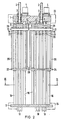
- each threaded spindle 2 is arranged on a base plate 1, which are actuated by means of drive nuts 3 with an internal thread, which are rotatably mounted on the base plate 1 and whose outer ring gears 5 are in engagement with the pinions 6 of associated electric geared motors 4, so that each threaded spindle 2 can perform a movement perpendicular to the plane of the drawing.
- the push rods 18 have beads 19 at their upper ends and beads 20 of the same type at a distance from the desired axial stroke. Between these beads, the push rods are mounted in corresponding bores in the pressure strips. Between the pressure strips and the lower beads 20 there are helical springs 21 as compression springs. At its other end, the push rods 18 are axially displaceably supported by bores of the guide plate 17 which are congruent with those of the corresponding pressure bars 11, 12, 13, 14. The distance between the pressure bars and the guide plate corresponds approximately to the length of the fuel rods to be pushed out of the reactor fuel assembly.
- mounting plates 22, 23, 24, 25 (FIGS. 2 and 4) are arranged, which are connected by means of push rods 26 to the pressure bars 11, 12, 13, 14 assigned to them are.
- the push rods 26 are fixed to the mounting plates and axially slidably connected to the pressure bars 11, 12, 13, 14. In this way, it is possible to guide the push rods 18 without any significant loss of stroke.
- the push rods 26 stop while the pressure bars 11, 12, 13, 14 move further downward, so that in the end position the pressure bars 11, 12, 13, 14 on the mounting plates 22, 23, 24, 25 and these rest on the guide plate 17.
- the pressure bar assigned to it e.g. 12
- the switching bar actuates a proximity switch 32 which is attached to the relevant pressure bar via spacers 31 and which switches off the drive means of this pressure bar.
- the jammed fuel rod must then be removed with a special pulling tool.
- FIG. 3 shows a possible arrangement of the push rods in cross section.
- the push rods are arranged in rows in the grid dimension of the fuel assembly but in different numbers per row. The reason for this is that there must be gaps for control rod guide tubes between the two rods in a geometry that is dependent on the physical conditions, which gaps remain in the fuel assembly.
- the arrangement of the rods according to FIG. 3 now offers the possibility of pushing out smaller or larger quantities of rods within the grid geometry of the fuel assembly, depending on the situation found.
- the base plate 1 and the guide plate 17 are fastened to a coordinate transport system 33, 34 (FIGS. 2 and 4), which makes it possible to transport the printing device to the fuel assembly in the respectively desired position.
- the push rods 18 can be hemispherical or funnel-shaped at their ends facing the fuel assembly in such a way that they at least partially enclose the plugs of the fuel rods, so that the fuel rods cannot slide sideways under the pressure.
- FIG. 5 a variant of the printing device according to Fig. 2 is shown in a further longitudinal section, in which an additional mounting plate (e.g. 36), sliding on guide rods 16, axially displaceable via push rods 37, which correspond in function to the push rods 26 is held on the associated guide plate (e.g. 23).
- the function of these additional mounting plates corresponds to the already described mounting plates 22, 23, 24. 25. If it should prove necessary, mounting plates can be arranged in a corresponding manner in further levels.
- FIG. 6 A further embodiment of the printing device is shown in FIG. 6 as a sectional front view, the sectional plane of which corresponds to that of FIG. 5.
- the structurally and functionally the same components are provided with the same reference numerals as in the previous embodiment.
- the principle of operation differs from that of the above-described embodiment in that instead of a spindle drive for the push rods, a hydraulic drive with the cylinder 38 and the piston 39 is used. This is firmly connected to the bracket 40 of the pressure bar 41.
- the push rods 42 are not axially displaceably mounted on the pressure bar 41 against spring pressure around the switching stroke for actuating a proximity switch, but rather are fastened to the pressure bar 41 by means of shear pins 44.
- the result of this is that when one of the fuel rods is jammed in the spacers of the fuel assembly, the shear pin of the push rod in question shears off, so that the rod remains in this position, but the drive itself is not interrupted.
- the piston 39 thus guides the remaining push rods to their lower end position. The stuck fuel rod can then be removed with a special drawing tool and treated separately.
- the two middle push rods are missing, because if they stood still, they would block the piston 39 arranged above them with the bracket 40.
- a possible fallback could be the two middle pressures rods do not attach to the pressure bar 41 with shear pins, but, according to the previous embodiment, axially sliding against spring pressure to support such a stroke that they interrupt the hydraulic drive in the event of a blockage by actuating a proximity switch.
- the piston 39 with the bracket 40 could be arranged offset by a corresponding amount perpendicular to the direction of the row of push rods.
- FIGS. 7 to 10 A printing device designed in this way is shown in FIGS. 7 to 10. According to the top view according to FIG. 7, a single spindle drive with the spindle 46, the drive motor 47 and the gear nut 48 is arranged on a base plate 45.
- the push rods 49 are fastened as a complete group in an arrangement corresponding to the grid geometry of the fuel assembly on a single pressure plate 50 (FIG. 9).
- the type of attachment is shown in FIG. 8 and corresponds to that according to FIG. 2.
- the push rods 49 are thus arranged in corresponding bores of the pressure plate 50 against spring pressure by a certain axial stroke.
- a switching plate 51 is provided in the present case, as shown in FIG. 9, which is stopped by the relevant push rod in the event of a fuel rod jamming and thereby actuates the proximity switch 32, which interrupts the drive motor 47.
- the base plate 45 is fixedly connected to the guide plate 52 via four guide rods 16 (FIG. 8). Both are in turn at such a distance from one another that the lifting movement of the pressure plate 50 corresponding to the length of the fuel rods to be pushed out can be carried out.
- the guide plate 52 has congruent bores with those of the pressure plate 50, in which the pressure rods 49 are axially displaceably mounted.
- the pressure plate 50 slides in ball bushings 53 on the guide rods 16 and is actuated by the spindle 46 via a bracket 54. For this purpose, the spindle 46 is attached to the bracket 54.
- a mounting plate 55 is in turn arranged between the pressure plate 50 and the guide plate 52, which is held on the pressure plate 50 by means of four push rods 56.
- the push rods 56 are fixed to the mounting plate 55 and axially slidably connected to the pressure plate 50. Their function is the same as already described in Fig. 2.
- a tubular holder 58 which is fastened to the base plate 45 with a flange 57, is used. It has the advantage that it is simpler in terms of both the technical design and the handling than the aforementioned coordinate transport system. This advantage is particularly important when the fuel rods can be pushed out in groups, as in the present exemplary embodiment, so that the position of the printing device relative to the fuel element does not have to be changed as often as, for example, when the fuel rods are pushed out in rows.
- the pressure device can be hung via the pipe holder on the lifting device usually present above the reactor pressure vessel and can be conveyed to the fuel element in the desired position with the aid thereof.
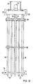
- a particularly favorable use of space results from a further embodiment variant according to FIGS. 11 and 12 through a different design of the spindle drive. It is not the gear nuts on the base plate that are moved by the drive motor, but the threaded spindles themselves.
- the two threaded spindles 60, 61 vertically displacing the pressure plate 59 can be rotated in the base plate 62 and in the guide plate 63 and are each rotatably mounted on the pressure plate 59 in a threaded nut 64 which is firmly connected to the latter.
- Each threaded spindle has a friction plate 65, 66 on its drive-side ends protruding from the base plate 62, which are set in rotation by a drive motor 67, 68 or - using appropriate transmission means - by a single drive motor.
- the threaded spindles themselves are not subject to any vertical movement. Only the pressure plate 59 together with the pressure rods 42 perform the desired vertical lifting movement.
- the guide plate 63 has congruent bores for the pressure rods 42 and the guide rods 16 with those of the mounting plate 55 and the pressure plate 59.
- the mounting of the pressure rods 42 on the pressure plate 59 corresponds functionally to that according to FIG. 6.
- the other construction elements having the same function as the previous exemplary embodiments are provided with the same reference numerals.
Landscapes
- Engineering & Computer Science (AREA)
- Physics & Mathematics (AREA)
- Plasma & Fusion (AREA)
- General Engineering & Computer Science (AREA)
- High Energy & Nuclear Physics (AREA)
- Mechanical Engineering (AREA)
- Monitoring And Testing Of Nuclear Reactors (AREA)
- Transmission Devices (AREA)
- Devices And Processes Conducted In The Presence Of Fluids And Solid Particles (AREA)
- Automatic Assembly (AREA)
- Cleaning In General (AREA)
Description
Die Erfindung betrifft eine Druckvorrichtung der im Oberbegriff des Anspruchs 1 näher bezeichneten Art.The invention relates to a printing device of the type specified in the preamble of
In der EP-A-83 10 7568.4 ist eine sogenannte Dichtsetzvorrichtung für abgebrannte Brennstäbe aus Reaktor-Brennelementen beschrieben, die dazu dient, aus einem Reaktor-Brennelement entnommene Brennstäbe in dichtest möglicher, vorzugsweise hexagonal dichtester Packung zusammenzudrükken und in einen Lagerungsbehälter zu überführen. Dazu ist es notwendig, die Brennstäbe mit Hilfe einer Druckvorrichtung aus den Abstandshaltern eines Reaktor-Brennelementes auszuschieben und über ein Führungsmittel, beispielsweise ein Führungsrohrbündel, in die Dichtsetzvorrichtung einzuführen.EP-A-83 10 7568.4 describes a so-called sealing device for spent fuel rods from reactor fuel assemblies, which is used to squeeze fuel rods removed from a reactor fuel assembly into the closest possible, preferably hexagonally tightest packing and to transfer them to a storage container. For this purpose, it is necessary to push the fuel rods out of the spacers of a reactor fuel element with the aid of a pressure device and to insert them into the sealing device via a guide means, for example a bundle of guide tubes.
Es ist der Zweck der vorliegenden Erfindung, eine Druckvorrichtung dieser Art so zu gestalten, daß es gelingt, möglichst viele, im Extremfall alle Brennstäbe gleichzeitig aus einem Brennelement auszuschieben und über das Führungsrohrbündel in die Dichtsetzvorrichtung einzubringen. Sofern das gleichzeitige Ausschieben aller Brennstäbe auf Schwierigkeiten stößt, soll es möglich sein, die Brennstäbe reihenweise oder gruppenweise auszuschieben.It is the purpose of the present invention to design a pressure device of this type in such a way that it is possible to push as many, in the extreme case all fuel rods, out of a fuel element at the same time and to insert them into the sealing device via the guide tube bundle. If the simultaneous pushing out of all fuel rods encounters difficulties, it should be possible to push the fuel rods out in rows or in groups.
Nachdem die Brennstäbe während ihrer Arbeitsphase einer relativ hohen thermischen Belastung ausgesetzt sind und auch chemischen Einflüssen unterliegen, kann es vorkommen, daß sich einzelne Brennstäbe in den Abstandshaltern verklemmen. In einem solchen Fall soll die Druckvorrichtung, um größere Schäden zu vermeiden, oberhalb eines bestimmten Druckes insgesamt abgeschaltet werden, mindestens soll aber die Krafteinwirkung auf den betreffenen Brennstab unterbrochen werden.After the fuel rods are exposed to a relatively high thermal load during their working phase and are also subject to chemical influences, it may happen that individual fuel rods get jammed in the spacers. In such a case, in order to avoid major damage, the pressure device should be switched off overall above a certain pressure, but at least the action of force on the fuel rod in question should be interrupted.
Der Erfindung liegt die Aufgabe zugrunde, eine Druckvorrichtung der eingangs beschriebenen Art für diese Zwecke so zu gestalten, daß sie unter Berücksichtigung des geometrischen Teilungsmaßes des zu entleerenden Brennelemen- in der Lage ist, eine gewünschte Anzahl von Brennstäben, in Sonderheit alle Brennstäbe gleichzeitig aus der Brennelementhalterung auszuschieben und in ein Führungsmittel zum Zwecke der Einbringung in eine Dichtsetzvorrichtung einzuführen.The invention has for its object to design a printing device of the type described for this purpose so that it is capable of taking into account the geometric pitch of the fuel elements to be emptied - a desired number of fuel rods, in particular all fuel rods simultaneously from the Push out the fuel assembly holder and insert it into a guide means for the purpose of insertion into a sealing device.
Diese Aufgabe wird durch die gemäß Patentanspruch 1 gestaltete Druckvorrichtung gelöst. Vorteilhafte Weiterbildungen und Ausgestaltungen der Druckvorrichtung nach Patenanspruch 1 sind in den Unteransprüchen gekennzeichnet.This object is achieved by the printing device designed according to
Zwei Ausführungsbeispiele der Erfindung sind anhand von Zeichungen im folgenden näher erläutert. Es zeigen :
Figur 1 eine Draufsicht auf eine bestimmte Ausführungsform der Druckvorrichtung, von der inFigur 2 ein Teillängsschnitt in Vorderansicht, in- Figur 3 ein Querschnitt, in
Figur 4 eine Seitenansicht und inFigur 5 eine Vorderansicht mit zusätzlichen Halterungsmitteln dargestellt ist ;Figur 6 eine Vorderansicht einer Ausführungsform mit einem anderen Antriebssystem und anderer Druckstangenbefestigung,- Figur 7 eine Draufsicht auf eine weitere Ausführungsform, von der in
Figur 8 ein Teillängsschnitt in Vorderansicht, in- Figur 9 eine Seitenansicht und in
Figur 10 ein Querschnitt gezeigt sind und schließlichFigur 11 eine Vorderansicht einer gegenüber- Fig. 1 modifizierten Ausführungsform, von der in
Figur 12 eine Seitenansicht dargestellt ist.
- Figure 1 is a plan view of a specific embodiment of the printing device, of which in
- Figure 2 is a partial longitudinal section in front view, in
- Figure 3 is a cross section in
- Figure 4 is a side view and in
- FIG. 5 shows a front view with additional mounting means;
- FIG. 6 shows a front view of an embodiment with a different drive system and a different push rod fastening,
- Figure 7 is a plan view of another embodiment, of which in
- Figure 8 is a partial longitudinal section in front view, in
- Figure 9 is a side view and in
- Figure 10 shows a cross section and finally
- Figure 11 is a front view of an opposite
- Fig. 1 modified embodiment, of which a side view is shown in Figure 12.
Gemäß Fig. 1 sind auf einer Grundplatte 1 vier gleichartige Gewindespindeln 2 angeordnet, die mit Hilfe von auf der Grundplatte 1 drehbar gelagerten Antriebsmuttern 3 mit Innengewinde, deren äußere Zahnkränze 5 mit den Ritzeln 6 von zugeordneten elektrischen Getriebemotoren 4 in Eingriff sind, betätigt werden, so daß jede Gewindespindel 2 eine Bewegung senkrecht zur Zeichnungsebene ausführen kann.1, four identical threaded
Aus dem in Fig. 2 dargestellten Teillängsschnitt durch die Druckvorrichtung ist in Verbindung mit Fig. 4 zu erkennen, daß die von den drehbar gelagerten Antriebsmuttern 3 axial bewegten Gewindespindeln 2 an Bügeln 7, 8, 9, 10 befestigt sind, die ihrerseits mit Druckleisten 11, 12, 13, 14, fest verbunden sind. Diese Leisten sind in Kugelbüchsen 15 auf Führungsstangen 16 axial verschiebbar gelagert. Die Führungsstangen 16 verbinden die Grundplatte 1 mit einer Führungsplatte 17. Beide befinden sich in einem solchen Abstand voneinander, daß die der Länge der auszuschiebenden Brennstäbe entsprechende Hubbewegung der Druckleisten 11, 12, 13, 14 zwischen beiden Platten ausgeführt werden kann. Zum Ausdrücken der Brennstäbe sind in entsprechender geometrischer Anordnung (Fig. 3) Druckstangen 18 vorhanden, welche an den Druckleisten 11, 12, 13, 14 um einen gewissen Axialhub gegen Federdruck verschiebbar gelagert sind. Zu diesem Zweck besitzen die Druckstangen 18 an ihren oberen Enden Wülste 19 und, im Abstand des gewünschten Axialhubes, gleichartige Wülste 20. Zwischen diesen Wülsten sind die Druckstangen in ensprechenen Bohrungen der Druckleisten gelagert. Zwischen den Druckleisten und den unteren Wülsten 20 befinden sich Schraubenfedern 21 als Druckfedern. An ihrem anderen Ende sind die Druckstangen 18 durch mit denjenigen der entsprechenden Druckleisten 11, 12, 13, 14 deckungsgleiche Bohrungen der Führungsplatte 17 axial verschiebbar gelagert. Der Abstand zwischen den Druckleisten und der Führungsplatte entspricht etwa die Länge der aus dem Reaktor-Brennelement auszuschieben Brennstäbe.From the partial longitudinal section through the pressure device shown in FIG. 2 it can be seen in connection with FIG. 4 that the threaded
Um ein Durchbiegen der Druckstangen 18 unter Belastung zu vermeiden, sind im Zwischenraum zwischen den Druckleisten 11, 12, 13, 14 und der Führungsplatte 17 Halterungsplatten 22, 23, 24, 25 (Fig. 2 und 4) angeordnet, die mit Hilfe von Schubstangen 26 mit den ihnen zugeordneten Druckleisten 11, 12, 13, 14 verbunden sind. Die Schubstangen 26 sind mit den Halterungsplatten fest und mit den Druckleisten 11, 12, 13, 14 axial gleitend verbunden. Auf diese Weise ist es möglich, die Druckstangen 18 ohne nennenswerten Hubverlust einwandfrei zu führen. Beim Aufsitzen der Halterungsplatten 22, 23, 24, 25 auf der Führungsplatte 17 bleiben die Schubstangen 26 stehen, während sich die Druckleisten 11, 12, 13, 14 weiter nach unten bewegen, so daß in der Endstellung die Druckleisten 11, 12, 13, 14 auf den Halterungsplatten 22, 23, 24, 25 und diese auf der Führungsplatte 17 aufliegen. Oberhalb der Druckleisten 11.12.13,14 sind auf den Führungsstangen 16 in axialer Richtung gleitend gelagerte Schaltleisten 27, 28, 29, 30 angeordnet, die dann in Funktion treten, wenn sich beim Ausdrückvorgang ein Brennstab in den Abstandshaltern des Reaktor-Brennelementes verklemmt, so daß die betreffende Druckstange stehen bleibt. Dabei drückt die ihr zugeordnete Druckleiste (z. B. 12), die Schraubenfeder 21 der stehengebliebenen Druckstange zusammen, wobei die obere Wulst 19 dieser Druckstange zunächst auf die Schaltleiste (z. B. 28) trifft, die dann ebenfalls stehenbleibt. Kurz bevor die Druckleiste 12 die untere Wulst 20 der stehengebliebenen Druckstange erreicht, betätigt die Schaltleiste einen über Abstandshalter 31 an der betreffenden Druckleiste befestigten Näherungsschalter 32, der das Antriebsmittel dieser Druckleiste abschaltet. Der verklemmte Brennstab muß dann mit einem speziellen Ziehwerkzeug entfernt werden.In order to avoid bending of the
In Fig. 3 ist eine mögliche Anordnung der Druckstangen im Querschnitt dargestellt. Wie zu erkennen ist, sind die Druckstangen reihenweise im Rastermaß des Brennelementes aber in unterschiedlicher Anzahl pro Reihe angeordnet. Der Grund dafür liegt darin, daß zwischen den beiden Stäben in einer von den physikalischen Gegebenheiten abhängigen Geometrie Lücken für Steuerstab-Führungsrohre vorhanden sein müssen, die im Brennelement verbleiben. Die Anordnung der Stäbe nach Fig. 3 bietet nun die Möglichkeit, im Rahmen der Rastergeometrie des Brennelementes kleinere oder grössere Mengen von Stäben, je nach der vorgefundenen Situation, auszuschieben. Dazu sind die Grundplatte 1 und die Führungsplatte 17 an einem Koordinaten-Transportsystem 33, 34 (Fig. 2 und 4) befestigt, das es erlaubt, die Druckvorrichtung in die jeweils gewünschte Position zum Brennelement zu transportieren.3 shows a possible arrangement of the push rods in cross section. As can be seen, the push rods are arranged in rows in the grid dimension of the fuel assembly but in different numbers per row. The reason for this is that there must be gaps for control rod guide tubes between the two rods in a geometry that is dependent on the physical conditions, which gaps remain in the fuel assembly. The arrangement of the rods according to FIG. 3 now offers the possibility of pushing out smaller or larger quantities of rods within the grid geometry of the fuel assembly, depending on the situation found. For this purpose, the
Der Druckstangen 18 können an ihren dem Brennelement zugewandten Enden halbkugelförmig oder trichterförmig so ausgebildet sein, daß sie die Stopfen der Brennstäbe mindestens teilweise umschließen, so daß ein seitliches Wegrutschen der Brennstäbe unter der Druckeinwirkung vermieden ist.The
Aus der in Fig. 4 dargestellten teilweise geschnittenen Seitenansicht der Druckvorrichtung ist zu erkennen, wie die Druckleisten 11.12.13.14 mit den Bügeln 7, 8, 9, 10 und den Näherungsschaltern 32 gestaltet sind. Die Näherungsschalter 32 sprechen an, sobald die ihnen zugeordneten, in Kugelbüchsen 35 geführten Schaltleisten 27, 28, 29, 30 durch eine der Druckstangen 18 angehalten werden und in den Wirkungsbereich des Schalters 32 gelangen.It can be seen from the partially sectioned side view of the printing device shown in FIG. 4 how the pressure bars 11.12.13.14 are designed with the
In Fig. 5 ist in einem weiteren Längsschnitt eine Variante der Druckvorrichtung nach Fig. 2 dargestellt, bei der eine zustätzliche Halterungsplatte (z. B 36), auf Führungsstangen 16 gleitend, über Schubstangen 37, die in ihrer Funktion den Schubstangen 26 entsprechen, axialverschiebbar an der zugeordneten Führungsplatte (z. B. 23) gehaltert ist. Diese zusätzlichen Halterungsplatten entsprechen in ihrer Funktion den bereits beschriebenen Halterungsplatten 22, 23, 24. 25. Falls es sich als notwendig erweisen sollte können in weiteren Ebenen Halterungsplatten in entsprechender Weise angeordnet werden. Es ist natürlich auch möglich, die Schubstangen 26 der Halterungsplatten 22, 23, 24, 25 rohrförmig auszubilden und die Schubstangen 37 in diesen Rohren teleskopartig anzuordnen, so daß sich beide Schubstangen nach dem Aufsetzen der unteren Halterungsplatten auf die Führungsplatte 17 teleskopartig zusammenschieben.In Fig. 5, a variant of the printing device according to Fig. 2 is shown in a further longitudinal section, in which an additional mounting plate (e.g. 36), sliding on
Eine weitere Ausführungsform der Druckvorrichtung ist als schnittbildliche Vorderansicht, deren Schnittebene derjenigen der Fig. 5 entspricht, in Fig. 6 dargestellt. Dabei sind die konstruktiv und funktional gleichen Bauelemente mit den gleichen Bezugszeichen wie im vorigen Ausführungsbeispiel versehen.A further embodiment of the printing device is shown in FIG. 6 as a sectional front view, the sectional plane of which corresponds to that of FIG. 5. The structurally and functionally the same components are provided with the same reference numerals as in the previous embodiment.
Das Funktionsprinzip unterscheidet sich dadurch von demjenigen des vorbeschriebenen Ausführungsbeispieles, daß anstelle eines Spindelantriebes für die Druckstangen ein hydraulischer Antrieb mit dem Zylinder 38 und dem Kolben 39 benutzt ist. Dieser ist mit dem Bügel 40 der Druckleiste 41 fest verbunden. Außerdem sind die Druckstangen 42 nicht gegen Federdruck um den Schalthub zur Betätigung eines Näherungsschalters axial verschiebbar an der Druckleiste 41 gehaltert, sondern mit Hilfe von Scherstiften 44 an dieser befestigt. Dies hat zur Folge, daß beim Verklemmen eines der Brennstäbe in den Abstandshaltern des Brennelementes der Scherstift der betreffenden Druckstange abschert, so daß die Stange in dieser Position verharrt, der Antrieb selbst aber nicht unterbrochen wird. Der Kolben 39 führt also die übrigen Druckstangen bis in ihre untere Endposition. Der hängengebliebene Brennstab kann dann mit einem speziellen Ziehwerkzeug entfernt und gesondert behandelt werden.The principle of operation differs from that of the above-described embodiment in that instead of a spindle drive for the push rods, a hydraulic drive with the
Bei dem in Fig. 6 dargestellten Ausführungsbeispiel fehlen im Vergleich zur Ausführungsform nach Fig. 5 die beiden mittleren Druckstangen, weil diese beim Stehenbleiben den darüber angeordneten Kolben 39 mit dem Bügel 40 blockiren würden. Eine mögliche Ausweichlösung könnte darin bestehen, die beiden mittleren Druckstangen nicht mit Scherstiften an der Druckleiste 41 zu befestigen, sondern, entsprechend dem vorigen Ausführungsbeispiel, gegen Federdruck um einen solchen Hub axial gleitend zu lagern, daß sie im Fall der Blockade durch Betätigen eines Näherungsschalters den Hydraulikantrieb unterbrechen. Als weitere Alternativlösung könnte der Kolben 39 mit dem Bügel 40 um einen entsprechenden Betrag senkrecht zur Richtung der Druckstangenreihe versetzt angeordnet werden. Ferner wäre es möglich, die Führungsstangen 16 selbst als Kolben parallel arbeitender Hydraulikzylinder auszubilden, diese mit der Druckleiste 41 fest zu verbinden und in Kugelbüchsen gleitend an der Grundplatte 1 und der Führungsplatte 17 zu lagern, wobei diese mit separaten Distanzhaltern aneinander zu befestigen wären.In the embodiment shown in FIG. 6, compared to the embodiment according to FIG. 5, the two middle push rods are missing, because if they stood still, they would block the
Es wurde bereits erwähnt, daß die Druckvorrichtung erfindungsgemäß auch so gestaltet werden kann, daß die Brennstäbe gruppenweise aus dem Brennelement auszuschieben sind. Eine so gestaltete Druckvorrichtung ist in den Figuren 7 bis 10 dargestellt. Gemäß der Draufsicht nach Fig. 7 ist auf einer Grundplatte 45 ein einziger Spindelantrieb mit der Spindel 46, dem Antriebsmotor 47 und der Getriebemutter 48 angeordnet.It has already been mentioned that the printing device according to the invention can also be designed such that the fuel rods can be pushed out of the fuel assembly in groups. A printing device designed in this way is shown in FIGS. 7 to 10. According to the top view according to FIG. 7, a single spindle drive with the
Aus der Querschnittsdarstellung in Fig. 10 ist zu erkennen, daß die Druckstangen 49 als komplette Gruppe in einer der Rastergeometrie des Brennelementes entsprechenden Anordnung an einer einzigen Druckplatte 50 befestigt sind (Fig. 9). Die Art der Befestigung ist in Fig. 8 dargestellt und entspricht derjenigen nach Fig. 2. Die Druckstangen 49 sind also in entsprechenden Bohrungen der Druckplatte 50 gegen Federdruck um einen gewissen Axialhub verschiebbar angeordnet. Anstelle einer Schaltleiste zur Betätigung des Näherungsschalters 32 wie in Fig. 2 ist im vorliegenden Fall gemäß der Darstellung in Fig. 9 eine Schaltplatte 51 vorgesehen, die im Falle des Verklemmens eines Brennstabes durch die betreffende Druckstange angehalten wird und dabei den Näherungsschalter 32 betätigt, der den Antriebsmotor 47 unterbricht. Die Grundplatte 45 ist über vier Führungsstangen 16 mit der Führungsplatte 52 fest verbunden (Fig. 8). Beide befinden sich wiederum in einem solchen Abstand voneinander, daß die der Länge der auszuschiebenden Brennstäbe entsprechende Hubbewegung der Druckplatte 50 ausgeführt werden kann. Die Führungsplatte 52 besitzt mit denjenigen der Druckplatte 50 deckungsgleiche Bohrungen, in denen die Druckstangen 49 axial verschiebbar gelagert sind. Die Druckplatte 50 gleitet in Kugelbüchsen 53 auf den Führungsstangen 16 und wird über einen Bügel 54 von der Spindel 46 betätigt. Dazu ist die Spindel 46 am Bügel 54 befestigt. Um ein Durchbiegen der Druckstangen 49 zu vermeiden, ist wiederum zwischen der Druckplatte 50 und der Führungsplatte 52 eine Halterungsplatte 55 angeordnet, die mit Hilfe von vier Schubstangen 56 an der Druckplatte 50 gehaltert ist. Die Schubstangen 56 sind mit der Halterungsplatte 55 fest und mit der Druckplatte 50 axial gleitend verbunden. Ihre Funktion ist die gleiche wie bereits in Fig. 2 beschrieben.It can be seen from the cross-sectional illustration in FIG. 10 that the
Ferner ist anstelle eines Koordinaten-Transportsystems eine mit einem Flansch 57 auf der Grundplatte 45 befestigte rohrförmige Halterung 58 benutzt. Sie hat den Vorteil, daß sie sowohl hinsichtlich der technischen Ausführung als auch der Handhabung einfacher ist, als das vorerwähnte Koordinaten-Transportsystem. Dieser Vorteil kommt vor allem dann zum Tragen, wenn die Brennstäbe wie im vorliegenden Ausführungsbeispiel, gruppenweise ausgeschoben werden können, so daß die Position der Druckvorrichtung gegenüber dem Brennelement nicht so häufig geändert werden muß, wie beispielsweise beim reihenweisen Ausschieben der Brennstäbe. Die Druckvorrichtung kann über die Rohrhalterung an das oberhalb des Reaktor-Druckbehälters üblicherweise vorhandene Hebezeug gehängt und mit dessen Hilfe in die gewünschte Position zum Brennelement befördert werden.Furthermore, instead of a coordinate transport system, a
Eine besonders günstige Raumausnutzung ergibt sich nach einer weiteren Ausführungsvariante gemäß den Figuren 11 und 12 durch eine andere Gestaltung des Spindelantriebs. Dabei sind nicht die auf der Grundplatte gelagerten Getriebemuttern vom Antriebsmotor bewegt, sondern die Gewindespindeln selbst.A particularly favorable use of space results from a further embodiment variant according to FIGS. 11 and 12 through a different design of the spindle drive. It is not the gear nuts on the base plate that are moved by the drive motor, but the threaded spindles themselves.
Dazu sind die beiden, die Druckplatte 59 vertikal verschiebenden Gewindespindeln 60, 61 in der Grundplatte 62 sowie in der Führungsplatte 63 drehbar und an der Druckplatte 59 in je einer mit dieser fest verbundenen Gewindemutter 64 drehbar gelagert. Jede Gewindespindel besitzt an ihren aus der Grundplatte 62 herausragenden antriebsseitig Enden eine Friktionsscheibe 65, 66, die von je einem Antriebsmotor 67, 68 oder - unter Verwendung entsprechender Übertragungsmittel - von einem einzigen Antriebsmotor in Drehung versetzt werden. Im Gegensatz zu den vorbeschriebenen Beispielen unterliegen dabei die Gewindespindeln selbst keiner Vertikalbewegung. Nur die Druckplatte 59 führt zusammen mit den Druckstangen 42 die gewünschte vertikale Hubbewegung aus. Dadurch reduziert sich die erforderliche Bauhöhe der Druckvorrichtung auf etwa die Hälfte derjenigen der vorbeschriebenen Ausführungsbeispiele. Die Führungsplatte 63 besitzt wiederum mit denjenigen der Halterungsplatte 55 und der Druckplatte 59 deckungsgleiche Bohrungen für die Druckstangen 42 und die Führungsstangen 16. Die Halterung der Druckstangen 42 an der Druckplatte 59 entspricht funktionell derjenigen nach Fig. 6. Die übrigen mit den vorigen Ausführungsbeispielen funktionsgleichen Konstruktionselemente sind mit den gleichen Bezugszeichen versehen.For this purpose, the two threaded
Claims (8)
Applications Claiming Priority (2)
| Application Number | Priority Date | Filing Date | Title |
|---|---|---|---|
| DE19833331761 DE3331761A1 (en) | 1983-09-02 | 1983-09-02 | PRINTING DEVICE FOR EXHAUSTING FUEL STICKS FROM A CORE REACTOR FUEL ELEMENT |
| DE3331761 | 1983-09-02 |
Publications (2)
| Publication Number | Publication Date |
|---|---|
| EP0134841A1 EP0134841A1 (en) | 1985-03-27 |
| EP0134841B1 true EP0134841B1 (en) | 1987-08-19 |
Family
ID=6208126
Family Applications (1)
| Application Number | Title | Priority Date | Filing Date |
|---|---|---|---|
| EP83112094A Expired EP0134841B1 (en) | 1983-09-02 | 1983-12-01 | Pushing device for ejecting fuel rods from a nuclear reactor fuel element |
Country Status (6)
| Country | Link |
|---|---|
| US (1) | US4673544A (en) |
| EP (1) | EP0134841B1 (en) |
| JP (1) | JPS6056297A (en) |
| KR (1) | KR850002346A (en) |
| DE (2) | DE3331761A1 (en) |
| ES (1) | ES8702069A1 (en) |
Families Citing this family (11)
| Publication number | Priority date | Publication date | Assignee | Title |
|---|---|---|---|---|
| GB2165688B (en) * | 1984-08-21 | 1988-06-22 | Atomic Energy Authority Uk | Dismantling irradiated nuclear fuel elements |
| FR2591021B1 (en) * | 1985-12-02 | 1988-02-26 | Cogema | DEVICE FOR GRIPPING A BEAM OF PENCILS OF A NUCLEAR FUEL ASSEMBLY |
| FR2596565B1 (en) * | 1986-04-01 | 1988-07-01 | Cogema | PROCESS FOR FITTING A BEAM OF PENCILS OF A NUCLEAR FUEL ASSEMBLY AND INSTALLATION FOR CARRYING OUT SAID METHOD |
| US4800061A (en) * | 1987-05-06 | 1989-01-24 | Westinghouse Electric Corp. | Apparatus for loading fuel rods into grids of nuclear fuel assemblies |
| DE3883621T2 (en) * | 1987-06-18 | 1994-04-28 | Westinghouse Electric Corp | System for pushing out and compacting fuel rods of a nuclear fuel rod bundle. |
| US5000906A (en) * | 1987-06-18 | 1991-03-19 | Westinghouse Electric Corp. | System and method for removing and consolidating the fuel rods of a nuclear fuel assembly |
| US4952072A (en) * | 1987-06-18 | 1990-08-28 | Westinghouse Electric Corp. | System and method for removing and consolidation fuel rods of a nuclear fuel assembly |
| US4968477A (en) * | 1989-02-02 | 1990-11-06 | Westinghouse Electric Corp. | Method and apparatus for removing the fuel rods of a nuclear fuel assembly |
| WO1993016840A1 (en) * | 1992-02-28 | 1993-09-02 | Combustion Engineering, Inc. | O.d. gripper |
| FR2836753B1 (en) * | 2002-03-01 | 2004-07-16 | Framatome Anp | METHOD FOR DESIGNING THE SPIDER SPRING OF A CONTROL CLUSTER OF A NUCLEAR FUEL ASSEMBLY, CORRESPONDING SYSTEM, COMPUTER PROGRAM AND PRODUCT |
| CN102862043B (en) * | 2012-08-10 | 2015-01-07 | 吴江市博众精工科技有限公司 | Compaction mechanism |
Family Cites Families (10)
| Publication number | Priority date | Publication date | Assignee | Title |
|---|---|---|---|---|
| GB844168A (en) * | 1957-06-19 | 1960-08-10 | Hawker Siddeley Nuclear Power | Improvements in and relating to mechanical handling means, more particularly for loading and unloading nuclear reactors of the solid fuel type |
| BE638999A (en) * | 1962-10-26 | |||
| US3501826A (en) * | 1967-04-21 | 1970-03-24 | Western Electric Co | Apparatus for assembling a pair of articles one within the other |
| US3510012A (en) * | 1968-08-15 | 1970-05-05 | Lummus Co | Tube bundle handling apparatus |
| DE2054394A1 (en) * | 1970-10-14 | 1972-04-20 | Bbc Brown Boveri & Cie | Gas cooled reactor fuel element - assembled in matrix of cylindrical holes in a graphite sleeve |
| FR2158112A1 (en) * | 1971-11-03 | 1973-06-15 | Creusot Loire | Nuclear fuel rod manipulator - for inserting,with drawing and transferring rods in reactor core |
| DE2623103A1 (en) * | 1976-05-22 | 1977-12-01 | Interatom | Removing groups of rods from nuclear fuel elements - by several grabs operated from one control unit |
| US4358421A (en) * | 1977-10-26 | 1982-11-09 | The Babcock & Wilcox Company | Industrial technique |
| EP0066695B1 (en) * | 1981-05-29 | 1986-01-22 | Westinghouse Electric Corporation | Spent fuel consolidation apparatus |
| US4551299A (en) * | 1982-09-15 | 1985-11-05 | Westinghouse Electric Corp. | Multiple fuel rod gripper |
-
1983
- 1983-09-02 DE DE19833331761 patent/DE3331761A1/en not_active Withdrawn
- 1983-12-01 EP EP83112094A patent/EP0134841B1/en not_active Expired
- 1983-12-01 DE DE8383112094T patent/DE3373159D1/en not_active Expired
- 1983-12-23 ES ES528362A patent/ES8702069A1/en not_active Expired
- 1983-12-26 JP JP58252354A patent/JPS6056297A/en active Granted
-
1984
- 1984-02-15 KR KR1019840000700A patent/KR850002346A/en not_active IP Right Cessation
- 1984-02-16 US US06/580,693 patent/US4673544A/en not_active Expired - Fee Related
Also Published As
| Publication number | Publication date |
|---|---|
| US4673544A (en) | 1987-06-16 |
| ES528362A0 (en) | 1986-12-01 |
| KR850002346A (en) | 1985-05-10 |
| JPS6056297A (en) | 1985-04-01 |
| EP0134841A1 (en) | 1985-03-27 |
| JPH0242440B2 (en) | 1990-09-21 |
| DE3331761A1 (en) | 1985-03-21 |
| DE3373159D1 (en) | 1987-09-24 |
| ES8702069A1 (en) | 1986-12-01 |
Similar Documents
| Publication | Publication Date | Title |
|---|---|---|
| EP0134841B1 (en) | Pushing device for ejecting fuel rods from a nuclear reactor fuel element | |
| EP0388721A2 (en) | Press with tool frame insertable into the press | |
| DE1197165B (en) | Device for the automatic load-dependent deactivation of the electric drive motor of an electromechanical lifting device | |
| EP1385652A1 (en) | Hydro-mechanical clamp in particular for transverse extrusion | |
| DE3442446C2 (en) | ||
| DE3436075C1 (en) | Device for the releasable connection of gripper rail parts of the gripper rails in a transfer press | |
| DE3235040C2 (en) | Press for pressing on sleeves, cable lugs or the like | |
| DE2157274A1 (en) | Device for deforming or pressing | |
| EP0143257B1 (en) | Tool holding fixture for a punching press, particularly of a turret cutting press for tool changing | |
| DE2810595C2 (en) | Adjustment device for adjusting the closing height of a press | |
| DE2916272A1 (en) | PUNCHING MACHINE | |
| EP0557866A1 (en) | Scrap shear | |
| DE2308291B2 (en) | Actuator with spring back for valves and the like | |
| EP0314975B1 (en) | Press with locking devices for the slide | |
| EP0266625B1 (en) | Upper tool holder for a punch or the like | |
| DE2838733A1 (en) | PROFILE STEEL SCISSORS AND / OR PUNCHING | |
| DE2011488A1 (en) | Workpiece feed device | |
| DE2318218A1 (en) | DEVICE FOR THE REGULATION AND RAPID SHUTDOWN OF NUCLEAR REACTORS | |
| DE19847973C1 (en) | Stepped work feed for press has auxiliary rail with pre-tensioned over load spring to control movement relative to main feed rail | |
| DE1752698C3 (en) | Device for the longitudinal advance of a slender pressure generating ram to be secured against buckling for hydrostatic extrusion or the like. Machine element or workpiece | |
| DE1047625B (en) | Press, scissors, punch or the like with overpressure protection | |
| CH669123A5 (en) | Filter press. | |
| EP0318459B1 (en) | Spindle drive | |
| DE3625979A1 (en) | Infinitely adjustable round dividing table | |
| DE2204182A1 (en) | CONTROL AND SHUTDOWN DEVICE FOR NUCLEAR REACTORS |
Legal Events
| Date | Code | Title | Description |
|---|---|---|---|
| PUAI | Public reference made under article 153(3) epc to a published international application that has entered the european phase |
Free format text: ORIGINAL CODE: 0009012 |
|
| AK | Designated contracting states |
Designated state(s): BE CH DE FR LI SE |
|
| 17P | Request for examination filed |
Effective date: 19850426 |
|
| 17Q | First examination report despatched |
Effective date: 19861028 |
|
| GRAA | (expected) grant |
Free format text: ORIGINAL CODE: 0009210 |
|
| AK | Designated contracting states |
Kind code of ref document: B1 Designated state(s): BE CH DE FR LI SE |
|
| REF | Corresponds to: |
Ref document number: 3373159 Country of ref document: DE Date of ref document: 19870924 |
|
| ET | Fr: translation filed | ||
| PLBE | No opposition filed within time limit |
Free format text: ORIGINAL CODE: 0009261 |
|
| STAA | Information on the status of an ep patent application or granted ep patent |
Free format text: STATUS: NO OPPOSITION FILED WITHIN TIME LIMIT |
|
| 26N | No opposition filed | ||
| PGFP | Annual fee paid to national office [announced via postgrant information from national office to epo] |
Ref country code: BE Payment date: 19891215 Year of fee payment: 7 |
|
| PGFP | Annual fee paid to national office [announced via postgrant information from national office to epo] |
Ref country code: SE Payment date: 19891220 Year of fee payment: 7 |
|
| PGFP | Annual fee paid to national office [announced via postgrant information from national office to epo] |
Ref country code: FR Payment date: 19891221 Year of fee payment: 7 |
|
| PGFP | Annual fee paid to national office [announced via postgrant information from national office to epo] |
Ref country code: DE Payment date: 19900226 Year of fee payment: 7 |
|
| PGFP | Annual fee paid to national office [announced via postgrant information from national office to epo] |
Ref country code: CH Payment date: 19900323 Year of fee payment: 7 |
|
| PG25 | Lapsed in a contracting state [announced via postgrant information from national office to epo] |
Ref country code: SE Effective date: 19901202 |
|
| PG25 | Lapsed in a contracting state [announced via postgrant information from national office to epo] |
Ref country code: LI Effective date: 19901231 Ref country code: CH Effective date: 19901231 Ref country code: BE Effective date: 19901231 |
|
| BERE | Be: lapsed |
Owner name: SIEMENS A.G. BERLIN UND MUNCHEN Effective date: 19901231 |
|
| PG25 | Lapsed in a contracting state [announced via postgrant information from national office to epo] |
Ref country code: FR Effective date: 19910830 |
|
| REG | Reference to a national code |
Ref country code: CH Ref legal event code: PL |
|
| PG25 | Lapsed in a contracting state [announced via postgrant information from national office to epo] |
Ref country code: DE Effective date: 19910903 |
|
| REG | Reference to a national code |
Ref country code: FR Ref legal event code: ST |
|
| EUG | Se: european patent has lapsed |
Ref document number: 83112094.4 Effective date: 19910910 |