EP0134748B1 - Variable width diffuser - Google Patents
Variable width diffuser Download PDFInfo
- Publication number
- EP0134748B1 EP0134748B1 EP84630128A EP84630128A EP0134748B1 EP 0134748 B1 EP0134748 B1 EP 0134748B1 EP 84630128 A EP84630128 A EP 84630128A EP 84630128 A EP84630128 A EP 84630128A EP 0134748 B1 EP0134748 B1 EP 0134748B1
- Authority
- EP
- European Patent Office
- Prior art keywords
- diffuser
- wall
- movable wall
- machine according
- vane
- Prior art date
- Legal status (The legal status is an assumption and is not a legal conclusion. Google has not performed a legal analysis and makes no representation as to the accuracy of the status listed.)
- Expired
Links
Images
Classifications
-
- F—MECHANICAL ENGINEERING; LIGHTING; HEATING; WEAPONS; BLASTING
- F04—POSITIVE - DISPLACEMENT MACHINES FOR LIQUIDS; PUMPS FOR LIQUIDS OR ELASTIC FLUIDS
- F04D—NON-POSITIVE-DISPLACEMENT PUMPS
- F04D29/00—Details, component parts, or accessories
- F04D29/40—Casings; Connections of working fluid
- F04D29/42—Casings; Connections of working fluid for radial or helico-centrifugal pumps
- F04D29/44—Fluid-guiding means, e.g. diffusers
- F04D29/46—Fluid-guiding means, e.g. diffusers adjustable
-
- F—MECHANICAL ENGINEERING; LIGHTING; HEATING; WEAPONS; BLASTING
- F01—MACHINES OR ENGINES IN GENERAL; ENGINE PLANTS IN GENERAL; STEAM ENGINES
- F01D—NON-POSITIVE DISPLACEMENT MACHINES OR ENGINES, e.g. STEAM TURBINES
- F01D17/00—Regulating or controlling by varying flow
- F01D17/10—Final actuators
- F01D17/12—Final actuators arranged in stator parts
- F01D17/14—Final actuators arranged in stator parts varying effective cross-sectional area of nozzles or guide conduits
- F01D17/141—Final actuators arranged in stator parts varying effective cross-sectional area of nozzles or guide conduits by means of shiftable members or valves obturating part of the flow path
- F01D17/143—Final actuators arranged in stator parts varying effective cross-sectional area of nozzles or guide conduits by means of shiftable members or valves obturating part of the flow path the shiftable member being a wall, or part thereof of a radial diffuser
-
- F—MECHANICAL ENGINEERING; LIGHTING; HEATING; WEAPONS; BLASTING
- F04—POSITIVE - DISPLACEMENT MACHINES FOR LIQUIDS; PUMPS FOR LIQUIDS OR ELASTIC FLUIDS
- F04D—NON-POSITIVE-DISPLACEMENT PUMPS
- F04D29/00—Details, component parts, or accessories
- F04D29/40—Casings; Connections of working fluid
- F04D29/42—Casings; Connections of working fluid for radial or helico-centrifugal pumps
- F04D29/44—Fluid-guiding means, e.g. diffusers
- F04D29/46—Fluid-guiding means, e.g. diffusers adjustable
- F04D29/462—Fluid-guiding means, e.g. diffusers adjustable especially adapted for elastic fluid pumps
- F04D29/464—Fluid-guiding means, e.g. diffusers adjustable especially adapted for elastic fluid pumps adjusting flow cross-section, otherwise than by using adjustable stator blades
-
- F—MECHANICAL ENGINEERING; LIGHTING; HEATING; WEAPONS; BLASTING
- F05—INDEXING SCHEMES RELATING TO ENGINES OR PUMPS IN VARIOUS SUBCLASSES OF CLASSES F01-F04
- F05D—INDEXING SCHEME FOR ASPECTS RELATING TO NON-POSITIVE-DISPLACEMENT MACHINES OR ENGINES, GAS-TURBINES OR JET-PROPULSION PLANTS
- F05D2250/00—Geometry
- F05D2250/50—Inlet or outlet
- F05D2250/52—Outlet
Definitions
- This invention relates to a centrifugal machine according to the precharacterizing portion of claim 1 or 8.
- Centrifugal compressors used in refrigeration systems are generally required to operate over a relatively large flow range.
- the efficiency and stability of the compressor is dependent upon the diffuser's ability to convert kinetic energy contained in the working fluid leaving the impeller into static pressure.
- the volumetric rate of flow through the diffuser correspondingly changes.
- the flow through the diffuser passage becomes unstable as the flow rate decreases below a certain level. Further reduction in the flow rate leads to a surge condition whereupon the working fluids undergo periodic flow reversals in the diffuser passage. This, of course, creates a good deal of unwanted noise and destroys the efficiency of the machine. If the rate of flow through the machine increases, the diffuser will be incapable of handling the flow through the fixed passage and a choke condition is soon reached which again adversely affects machine performance and efficiency.
- the width of the diffuser passages is changed in response to changes made in the position of compressor inlet guide vanes. Again, by matching the geometry of the diffuser to the inlet flow, surging at low flow rates is avoided. A similar device is also shown in US-A-4 219 305.
- variable width diffuser in conjunction with fixed diffuser guide vanes.
- This type of arrangement is shown in US-A-2 996 996 and 4 378 194 as well as in GB-A-305 214 which disclose the state of the art according to the precharacterizing portion of claims 1 or 8.
- the diffuser vanes are securely affixed, as by welding, to one of the opposed diffuser walls.
- the vanes are adapted to pass through openings formed in the other wall thus permitting the geometry of diffuser to be changed in response to changing load conditions.
- Fixedly mounting the diffuser blades to one of the diffuser walls presents a number of problems particularly in regard to the manufacture, maintenance and operation of the machine.
- the object of the present invention is to avoid alignment problems and to minimize leakage and uncontrollable pressure variations in a variable width diffuser section utilizing fixed diffuser guide vanes, and to provide self aligning diffuser vanes in a movable wall diffuser than can be quickly replaced in assembly without having to tear down the machine.
- FIG. 1 illustrates a centrifugal compressor of the type utilized in the refrigeration art to raise the pressure of a refrigerant (working fluid) utilized in a cooling cycle.
- the machine is generally referenced 10 and includes an axial inlet 12 that directs the refrigerant into a rotating impeller wheel assembly 13 through a series of adjustable inlet guide vanes 15-15.
- the impeller is secured to a drive shaft 17 by any suitable means to align the impeller assembly along the axis 16 of the machine.
- the impeller assembly includes a central hub 18 that supports a series of contoured blades 19.
- the blades are arranged to create passages therebetween that turn the incoming axial flow of refrigerant in a radial direction and discharge the compressed refrigerant from the blade tips 20 into a diffuser section generally depicted at 22.
- the diffuser surrounds the impeller and functions to direct the compressed fluid into a toroidal-shaped volute or collector 23 which carries the fluids to the machine exhaust.
- the apparatus of the present invention involves a variable width diffuser having fixed diffuser guide vanes that can be utilized with equal effect in a wide variety of centrifugal machines.
- the machine shown herein is thus meant to be illustrative of a centrifugal compressor and not to be limiting in any sense.
- the term "fixed diffuser vane" is also used herein to define an airfoil whose pitch or angle of attack in regard to the compressed fluids moving through the diffuser passage does not change. The machine performance is herein altered while the machine is operated by adjusting the diffuser width.
- diffuser section 22 includes a radially disposed fixed wall 25 that forms the back wall of the diffuser section.
- the front wall 26 of the diffuser is also radially disposed in regard to the impeller and is arranged to move axially towards and away from the fixed wall to alter the width of the annular diffuser passage 40 and thus alter the machine's operating characteristics in regard to varying load demands.
- the movable front wall of the diffuser is secured to a carriage generally referenced 27.
- the carriage is movably mounted in the machine between shroud 28 and the main casing 30. Studs 37 are welded to the back of wall 26 and are adapted to pass through openings in the carriage 27. Nuts 33-33 are used to draw wall 26 tightly against the front face of the carriage.
- the wall 26 is accurately located in assembly by means of dowel pins, such as dowel 34.
- the carriage is illustrated in Fig. 2 as being fully retracted against the stop face 35 on the main casing to open the diffuser passage to a maximum flow handling condition.
- the carriage in turn, is securely affixed via screws 37 to a double acting piston 38.
- the piston may be driven either by gas or liquid, it shall be assumed for explanatory purposes it is liquid actuated.
- the piston is also slidably mounted between the previously noted shroud 28 and the main casing 30 so that it can move wall 26 through means of the carriage between the previously noted maximum flow position against stop 35 and a minimum flow position wherein the front face of the piston is brought against a stop 36.
- a first expandable chamber 43 is provided between the casing wall surface 44 and the front face 45 of the piston. Delivering fluid under pressure into the chamber drives the piston axially toward the fixed wall 25 of the diffuser.
- a second expandable chamber 47 is similarly located between the back wall surface 49 of the piston and the shroud wall 48. Directing fluid under pressure at this chamber causes the piston to be driven forward thus increasing the width of the diffuser passage.
- Fluid is delivered into the chambers from a supply reservoir, not shown, by means of a pair of flow circuits.
- the first flow circuit leading to chamber 43 includes flow channels 57 and 58.
- the second circuit is more complex and is made up of channels 53-56 which coact to deliver the drive fluid into the second chamber 47.
- the channels are formed by drilling communicating holes into the machine elements and plugging the holes where appropriate.
- inlet channels 53 and 57 are drilled one behind the other and thus appear as a single channel in Fig. 2. Both the inlet channels are connected to supply lines 61 by means of threaded couplings 62.
- a suitable control system 60 (Fig. 1) containing electrically actuated valves regulates the flow of the drive fluid into and out of the two expandable chambers to either move the piston towards or away from the fixed diffuser wall 25.
- An anti- rotation pin 39 passes between the piston and the machine casing which prevents the piston from turning in assembly.
- a series of 0-ring seals 50-50 encircle the piston and prevent fluid from passing along the piston wall between chambers.
- a series of fixed diffuser guide vanes 63-63 are equally spaced about the movable wall of the diffuser as illustrated in Fig. 3.
- the vanes can be of any suitable contour and generally take the shape of an airfoil for controlling the movement of working fluids through the diffuser passage.
- the vanes usually will turn the incoming flow leaving the tip of the impeller into a path that will combat unwanted noise and vibrations at low volumetric flow rates.
- the vanes are slidably contained in the movable wall within contoured holes 64-64 that complement closely the periphery of the vanes. A close running fit is provided therebetween to permit the vanes to move freely in the holes while at the same time minimizing fluid and pressure loss in the diffuser passage.
- each vane in the assembly Positioned immediately behind each vane in the assembly is a biasing spring 72.
- the spring is a compression coil that is seated at one end in a circular recess 74 formed in the rear wall of the carriage.
- the other end of each spring is loosely mounted upon a spring retaining element 66 that is pinned to the bottom surface 68 of an opposed vane via pin 67.
- the spring retaining element includes an expanded flange 69 that abuts the connected diffuser vane and a rearwardly projected cylinder 70 that passes into the spring coil.
- each spring is loaded between the carriage and the retainer flange to urge the bottom surface of the vane into secure seating contact against the interior surface of the fixed diffuser wall.
- each vane complements the receiving surface of the wall 25 and provides sufficient contact area so that the vane will not cant in assembly.
- This coupled with the slidable mounting of the vanes and the loose spring retention, allows each of the vanes to be self-aligning in assembly.
- the vanes thus can automatically alter their relative positions to accommodate for changes in the size and location of elements due to thermal growth or the like. Similarly, because of this independent flexible mounting structure, manufacturing and assembly tolerances can be considerably relaxed when compared to other variable wall diffusers having the vanes welded or bolted to one of the walls.
- a sensing rod 80 (Fig. 1) is slidably mounted within the machine casing by means of a mounting bracket 81.
- the rod is connected to a bellows 83 which functions to seal the rod within casing 30.
- the rod is adapted to move with the wall as it is moved to different positions.
- a sensing circuit 85 is operably connected to the proximal end of the rod by means of a pivot arm 87. The arm responds to the linear displacement of the rod to detect the exact position of the movable wall.
- Circuit means are provided which generate an output signal indicative of the wall position and this information is transmitted via data line 88 to control system 60 where it is used in conjunction with other load data to position the wall in an optimum position for any given load.
- the vaneless or uncontrolled radial distance along the diffuser passage is preferably maintained at about or less than 10% of the overall impeller radius in order to provide for good aerodynamic flow characteristics through the variable range of the diffuser. Also, because of the self-adjusting feature of the present blade arrangement, the clearance between the blades and the receiving opening can be held to about 0.254 mm (0.010") without the vanes binding in the holes as the movable wall is moved between the maximum and minimum flow positions.
Abstract
Description
- This invention relates to a centrifugal machine according to the precharacterizing portion of claim 1 or 8.
- Centrifugal compressors used in refrigeration systems are generally required to operate over a relatively large flow range. The efficiency and stability of the compressor, to a large extent, is dependent upon the diffuser's ability to convert kinetic energy contained in the working fluid leaving the impeller into static pressure. As the load on the machine changes, the volumetric rate of flow through the diffuser correspondingly changes. With a fixed diffuser geometry, the flow through the diffuser passage becomes unstable as the flow rate decreases below a certain level. Further reduction in the flow rate leads to a surge condition whereupon the working fluids undergo periodic flow reversals in the diffuser passage. This, of course, creates a good deal of unwanted noise and destroys the efficiency of the machine. If the rate of flow through the machine increases, the diffuser will be incapable of handling the flow through the fixed passage and a choke condition is soon reached which again adversely affects machine performance and efficiency.
- Many schemes have been devised to maintain high machine efficiencies over a wide operation range. In US-A-4 070 132, the entire impeller wheel configuration is varied in response to load changes in an effort to match the machine performance with the changing load demands. Adjustable diffuser flow restrictors are also described in US-A-3 362 625 which serve to regulate the flow within the diffuser in an effort to improve stability at low volumetric flow rates. Variable diffuser vanes as disclosed in US-A-3 957 392 are used for the same purpose. In US-A-3 251 539, a centrifugal refrigerant compressor is described having a movable diffuser wall that is used to change the width of the diffuser passage. The width of the diffuser passages is changed in response to changes made in the position of compressor inlet guide vanes. Again, by matching the geometry of the diffuser to the inlet flow, surging at low flow rates is avoided. A similar device is also shown in US-A-4 219 305.
- One effective technique for maintaining high operating efficiency over a wide flow range in a centrifugal machine is through use of the variable width diffuser in conjunction with fixed diffuser guide vanes. This type of arrangement is shown in US-A-2 996 996 and 4 378 194 as well as in GB-A-305 214 which disclose the state of the art according to the precharacterizing portion of claims 1 or 8. In these arrangements, the diffuser vanes are securely affixed, as by welding, to one of the opposed diffuser walls. The vanes are adapted to pass through openings formed in the other wall thus permitting the geometry of diffuser to be changed in response to changing load conditions. Fixedly mounting the diffuser blades to one of the diffuser walls presents a number of problems particularly in regard to the manufacture, maintenance and operation of the machine. Little space is afforded for securing the vanes in assembly. Any misalignment of the vanes will cause the vane to bind or rub against the opposite wall as it is being repositioned. Similarly, if one or more vanes in the series has to be replaced in assembly, the entire machine generally must be torn down to effect the replacement. This requires a good deal of down time and is costly. The receiving opening, through which the vanes pass are sometimes made overly large to avoid alignment problems. This can produce unwanted loss of working fluids and pressure variations in the diffuser region which again adversely affects performance. Lastly, the machine is generally exposed to thermal growth in the course of normal operations. The magnitude of growth may exceed manufacturing tolerance resulting in binding and/or rubbing problems as the width of the diffuser passage is being changed to meet changing load conditions.
- The object of the present invention is to avoid alignment problems and to minimize leakage and uncontrollable pressure variations in a variable width diffuser section utilizing fixed diffuser guide vanes, and to provide self aligning diffuser vanes in a movable wall diffuser than can be quickly replaced in assembly without having to tear down the machine.
- In accordance with the invention this is achieved by the features claimed in the characterizing portion of claim 1 or 8.
- For a better understanding of the centrifugal machine reference is now made to the following detailed description of the invention which is to be read in conjunction with the accompanying drawings, wherein:
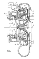
- Fig. 1 is a partial side elevation in section of a centrifugal machine embodying the teaching of the present invention;
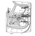
- Fig. 2 is an enlarged view of the upper portion of the machine illustrated in Fig. 1 further illustrating the variable width diffuser section utilized therein; and
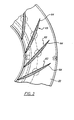
- Fig. 3 is a view taken along lines 3-3 in Fig. 2 showing a number of diffuser vanes slidably mounted in the movable wall of the diffuser.
- Referring now to the drawings wherein like numbers are used to identify like elements throughout, attention is initially directed to Fig. 1 which illustrates a centrifugal compressor of the type utilized in the refrigeration art to raise the pressure of a refrigerant (working fluid) utilized in a cooling cycle. The machine is generally referenced 10 and includes an
axial inlet 12 that directs the refrigerant into a rotatingimpeller wheel assembly 13 through a series of adjustable inlet guide vanes 15-15. The impeller is secured to adrive shaft 17 by any suitable means to align the impeller assembly along theaxis 16 of the machine. The impeller assembly includes acentral hub 18 that supports a series ofcontoured blades 19. The blades are arranged to create passages therebetween that turn the incoming axial flow of refrigerant in a radial direction and discharge the compressed refrigerant from theblade tips 20 into a diffuser section generally depicted at 22. The diffuser surrounds the impeller and functions to direct the compressed fluid into a toroidal-shaped volute orcollector 23 which carries the fluids to the machine exhaust. - The general construction of the centrifugal compressor is well known and, for this reason the structure of the machine is shown in somewhat schematic form in the drawings. As will become apparent from the disclosure below, the apparatus of the present invention involves a variable width diffuser having fixed diffuser guide vanes that can be utilized with equal effect in a wide variety of centrifugal machines. The machine shown herein is thus meant to be illustrative of a centrifugal compressor and not to be limiting in any sense. The term "fixed diffuser vane" is also used herein to define an airfoil whose pitch or angle of attack in regard to the compressed fluids moving through the diffuser passage does not change. The machine performance is herein altered while the machine is operated by adjusting the diffuser width.
- Referring now more specifically to Figs. 2 and 3,
diffuser section 22 includes a radially disposedfixed wall 25 that forms the back wall of the diffuser section. Thefront wall 26 of the diffuser is also radially disposed in regard to the impeller and is arranged to move axially towards and away from the fixed wall to alter the width of the annular diffuser passage 40 and thus alter the machine's operating characteristics in regard to varying load demands. In order to maximize the machine's efficiency in response to varying flow conditions, it is desirous to maintain the flow rate through the diffuser to just above the surge condition without causing a stall. - The movable front wall of the diffuser is secured to a carriage generally referenced 27. The carriage is movably mounted in the machine between
shroud 28 and themain casing 30.Studs 37 are welded to the back ofwall 26 and are adapted to pass through openings in thecarriage 27. Nuts 33-33 are used to drawwall 26 tightly against the front face of the carriage. Thewall 26 is accurately located in assembly by means of dowel pins, such asdowel 34. - The carriage is illustrated in Fig. 2 as being fully retracted against the
stop face 35 on the main casing to open the diffuser passage to a maximum flow handling condition. The carriage, in turn, is securely affixed viascrews 37 to a double acting piston 38. Although the piston may be driven either by gas or liquid, it shall be assumed for explanatory purposes it is liquid actuated. By introducing fluid under pressure to either side of the piston, its axial position, and thus that of the affixed carriage can be controlled in assembly. The piston is also slidably mounted between the previously notedshroud 28 and themain casing 30 so that it can movewall 26 through means of the carriage between the previously noted maximum flow position againststop 35 and a minimum flow position wherein the front face of the piston is brought against astop 36. - A first expandable chamber 43 is provided between the
casing wall surface 44 and thefront face 45 of the piston. Delivering fluid under pressure into the chamber drives the piston axially toward thefixed wall 25 of the diffuser. A secondexpandable chamber 47 is similarly located between the back wall surface 49 of the piston and theshroud wall 48. Directing fluid under pressure at this chamber causes the piston to be driven forward thus increasing the width of the diffuser passage. - Fluid is delivered into the chambers from a supply reservoir, not shown, by means of a pair of flow circuits. The first flow circuit leading to chamber 43 includes
flow channels 57 and 58. The second circuit is more complex and is made up of channels 53-56 which coact to deliver the drive fluid into thesecond chamber 47. - In practice, the channels are formed by drilling communicating holes into the machine elements and plugging the holes where appropriate. In practice, inlet channels 53 and 57 are drilled one behind the other and thus appear as a single channel in Fig. 2. Both the inlet channels are connected to supply
lines 61 by means of threadedcouplings 62. - A suitable control system 60 (Fig. 1) containing electrically actuated valves regulates the flow of the drive fluid into and out of the two expandable chambers to either move the piston towards or away from the fixed
diffuser wall 25. An anti-rotation pin 39 passes between the piston and the machine casing which prevents the piston from turning in assembly. A series of 0-ring seals 50-50 encircle the piston and prevent fluid from passing along the piston wall between chambers. Through manipulation of the control valves, the position of the carriage and thus the width of the diffuser passage can be closely regulated to match the performance characteristics to load demands. - A series of fixed diffuser guide vanes 63-63 are equally spaced about the movable wall of the diffuser as illustrated in Fig. 3. The vanes can be of any suitable contour and generally take the shape of an airfoil for controlling the movement of working fluids through the diffuser passage. The vanes usually will turn the incoming flow leaving the tip of the impeller into a path that will combat unwanted noise and vibrations at low volumetric flow rates. The vanes are slidably contained in the movable wall within contoured holes 64-64 that complement closely the periphery of the vanes. A close running fit is provided therebetween to permit the vanes to move freely in the holes while at the same time minimizing fluid and pressure loss in the diffuser passage.
- Positioned immediately behind each vane in the assembly is a biasing
spring 72. The spring is a compression coil that is seated at one end in a circular recess 74 formed in the rear wall of the carriage. The other end of each spring is loosely mounted upon a spring retaining element 66 that is pinned to thebottom surface 68 of an opposed vane viapin 67. The spring retaining element includes an expanded flange 69 that abuts the connected diffuser vane and a rearwardly projected cylinder 70 that passes into the spring coil. In assembly, each spring is loaded between the carriage and the retainer flange to urge the bottom surface of the vane into secure seating contact against the interior surface of the fixed diffuser wall. The action of the spring is such to hold the vane against the opposite wall over the entire travel distance of the carriage-piston combination between stops 35 and 36. Thebottom surface 73 of each vane complements the receiving surface of thewall 25 and provides sufficient contact area so that the vane will not cant in assembly. This, coupled with the slidable mounting of the vanes and the loose spring retention, allows each of the vanes to be self-aligning in assembly. The vanes thus can automatically alter their relative positions to accommodate for changes in the size and location of elements due to thermal growth or the like. Similarly, because of this independent flexible mounting structure, manufacturing and assembly tolerances can be considerably relaxed when compared to other variable wall diffusers having the vanes welded or bolted to one of the walls. - A sensing rod 80 (Fig. 1) is slidably mounted within the machine casing by means of a mounting
bracket 81. The rod is connected to abellows 83 which functions to seal the rod withincasing 30. The rod is adapted to move with the wall as it is moved to different positions. Asensing circuit 85 is operably connected to the proximal end of the rod by means of apivot arm 87. The arm responds to the linear displacement of the rod to detect the exact position of the movable wall. Circuit means are provided which generate an output signal indicative of the wall position and this information is transmitted viadata line 88 to controlsystem 60 where it is used in conjunction with other load data to position the wall in an optimum position for any given load. - The vaneless or uncontrolled radial distance along the diffuser passage is preferably maintained at about or less than 10% of the overall impeller radius in order to provide for good aerodynamic flow characteristics through the variable range of the diffuser. Also, because of the self-adjusting feature of the present blade arrangement, the clearance between the blades and the receiving opening can be held to about 0.254 mm (0.010") without the vanes binding in the holes as the movable wall is moved between the maximum and minimum flow positions.
Claims (15)
Applications Claiming Priority (2)
| Application Number | Priority Date | Filing Date | Title |
|---|---|---|---|
| US06/531,019 US4527949A (en) | 1983-09-12 | 1983-09-12 | Variable width diffuser |
| US531019 | 1983-09-12 |
Publications (3)
| Publication Number | Publication Date |
|---|---|
| EP0134748A2 EP0134748A2 (en) | 1985-03-20 |
| EP0134748A3 EP0134748A3 (en) | 1985-07-03 |
| EP0134748B1 true EP0134748B1 (en) | 1988-01-13 |
Family
ID=24115921
Family Applications (1)
| Application Number | Title | Priority Date | Filing Date |
|---|---|---|---|
| EP84630128A Expired EP0134748B1 (en) | 1983-09-12 | 1984-09-04 | Variable width diffuser |
Country Status (10)
| Country | Link |
|---|---|
| US (1) | US4527949A (en) |
| EP (1) | EP0134748B1 (en) |
| JP (1) | JPS6065299A (en) |
| KR (1) | KR870000017B1 (en) |
| AU (1) | AU551274B2 (en) |
| BR (1) | BR8404441A (en) |
| DE (1) | DE3468728D1 (en) |
| ES (1) | ES8701314A1 (en) |
| IN (1) | IN162216B (en) |
| MX (1) | MX167311B (en) |
Cited By (1)
| Publication number | Priority date | Publication date | Assignee | Title |
|---|---|---|---|---|
| DE4225126C1 (en) * | 1992-07-30 | 1993-04-01 | Mtu Muenchen Gmbh |
Families Citing this family (41)
| Publication number | Priority date | Publication date | Assignee | Title |
|---|---|---|---|---|
| US4844690A (en) * | 1985-01-24 | 1989-07-04 | Carrier Corporation | Diffuser vane seal for a centrifugal compressor |
| US4616483A (en) * | 1985-04-29 | 1986-10-14 | Carrier Corporation | Diffuser wall control |
| US4850795A (en) * | 1988-02-08 | 1989-07-25 | Dresser-Rand Company | Diffuser having ribbed vanes followed by full vanes |
| US4824325A (en) * | 1988-02-08 | 1989-04-25 | Dresser-Rand Company | Diffuser having split tandem low solidity vanes |
| US4902200A (en) * | 1988-04-25 | 1990-02-20 | Dresser-Rand Company | Variable diffuser wall with ribbed vanes |
| GB2218744B (en) * | 1988-05-17 | 1992-03-18 | Holset Engineering Co | Variable geometry turbine |
| US4932835A (en) * | 1989-04-04 | 1990-06-12 | Dresser-Rand Company | Variable vane height diffuser |
| GB2234295B (en) * | 1989-07-21 | 1993-07-21 | Rolls Royce Plc | Gas turbine engine compressor assembly |
| US5082428A (en) * | 1990-08-16 | 1992-01-21 | Oklejas Robert A | Centrifugal pump |
| US5116197A (en) * | 1990-10-31 | 1992-05-26 | York International Corporation | Variable geometry diffuser |
| US5207559A (en) * | 1991-07-25 | 1993-05-04 | Allied-Signal Inc. | Variable geometry diffuser assembly |
| US5145317A (en) * | 1991-08-01 | 1992-09-08 | Carrier Corporation | Centrifugal compressor with high efficiency and wide operating range |
| US5569078A (en) * | 1995-03-06 | 1996-10-29 | Colorado State University Research Foundation | Air diffuser having fixed and variable outlet ports |
| US5807071A (en) * | 1996-06-07 | 1998-09-15 | Brasz; Joost J. | Variable pipe diffuser for centrifugal compressor |
| US5669756A (en) * | 1996-06-07 | 1997-09-23 | Carrier Corporation | Recirculating diffuser |
| GB2319811A (en) * | 1996-10-03 | 1998-06-03 | Holset Engineering Co | A variable geometry turbocharger for an internal combustion engine |
| JPH11117898A (en) * | 1997-10-09 | 1999-04-27 | Ebara Corp | Turbo machine |
| JP4573074B2 (en) * | 2000-05-24 | 2010-11-04 | 株式会社Ihi | Centrifugal compressor with variable diffuser and its control method |
| JP2001329995A (en) * | 2000-05-24 | 2001-11-30 | Ishikawajima Harima Heavy Ind Co Ltd | Centrifugal compressor with variable diffuser |
| US6431823B1 (en) * | 2000-07-13 | 2002-08-13 | Yudko Slepoy | Centrifugal pump with variable capacity and pressure |
| US20050002170A1 (en) * | 2003-07-01 | 2005-01-06 | Jacobs Neal Kenneth | Electronic device remote control keypad back lighting light pipe |
| DE102005012838A1 (en) * | 2005-03-19 | 2006-09-21 | Daimlerchrysler Ag | Exhaust gas turbocharger in internal combustion engine has diffuser wall which is adjustable between effective flow cross-section in diffuser reducing minimum position and flow cross-section releasing maximum position |
| NZ544309A (en) * | 2005-12-21 | 2007-07-27 | Hot Water Innovations Ltd | Variable pump |
| DE602006017746D1 (en) * | 2005-12-30 | 2010-12-02 | Ingersoll Rand Co | INTAKE SHAFT WITH GEARS FOR A CENTRIFUGAL COMPRESSOR |
| DE102006009354A1 (en) * | 2006-03-01 | 2007-09-06 | Bayerische Motoren Werke Ag | Centrifuge compressor, for a turbocharger, has a hollow elastic body to give a wide adjustment of the flow cross section surface of the diffuser |
| KR100909779B1 (en) * | 2008-02-01 | 2009-07-29 | 엘에스엠트론 주식회사 | Variable diffuser of compressor |
| GB2467964B (en) | 2009-02-24 | 2015-03-25 | Dyson Technology Ltd | Shroud-Diffuser assembly |
| KR20110067364A (en) * | 2009-12-14 | 2011-06-22 | (주)계양정밀 | Compressor of turbo-charger |
| US8616836B2 (en) | 2010-07-19 | 2013-12-31 | Cameron International Corporation | Diffuser using detachable vanes |
| GB2513666B (en) | 2013-05-03 | 2015-07-15 | Dyson Technology Ltd | Compressor |
| US9745999B2 (en) * | 2015-01-23 | 2017-08-29 | Hamilton Sundstrand Corporation | Compressor diffuser and shroud for a motor driven compressor |
| ITUA20161854A1 (en) * | 2016-03-21 | 2017-09-21 | Nuovo Pignone Tecnologie Srl | Centrifugal compressor with diffuser blades without flow loss and assembly method of a centrifugal compressor |
| CN105822602A (en) * | 2016-05-06 | 2016-08-03 | 哈尔滨工程大学 | Diffuser bypass anti-surge device |
| TWI607185B (en) * | 2016-12-09 | 2017-12-01 | 財團法人工業技術研究院 | Modulating mechanism of centrifugal compressor |
| CN107387459B (en) * | 2017-08-30 | 2019-01-29 | 北京航空航天大学 | A kind of centrifugal blower inlet guide vane and diffuser vane simultaneously match regulating mechanism |
| CN107606849A (en) * | 2017-09-27 | 2018-01-19 | 南京师范大学 | One kind may move shared refrigeration system and its operation method |
| CN110360130B (en) | 2018-04-09 | 2022-12-27 | 开利公司 | Variable diffuser drive system |
| KR20200015244A (en) * | 2018-08-03 | 2020-02-12 | 현대자동차주식회사 | Coolant pump, cooling system provided with the same for vehicle and control method for the same |
| TWI692584B (en) * | 2019-11-05 | 2020-05-01 | 財團法人工業技術研究院 | Centrifugal compressor |
| CN112682354B (en) * | 2020-12-18 | 2022-05-27 | 山东省章丘鼓风机股份有限公司 | Guide adjusting type sealing fan |
| US11788557B1 (en) * | 2022-05-06 | 2023-10-17 | Ingersoll-Rand Industrial U.S., Inc. | Centrifugal acceleration stabilizer |
Citations (1)
| Publication number | Priority date | Publication date | Assignee | Title |
|---|---|---|---|---|
| US4070123A (en) * | 1974-01-19 | 1978-01-24 | Daimler-Benz Aktiengesellschaft | Ball joint |
Family Cites Families (14)
| Publication number | Priority date | Publication date | Assignee | Title |
|---|---|---|---|---|
| DE409961C (en) * | 1923-10-28 | 1925-02-16 | Bbc Brown Boveri & Cie | Device to prevent flickering of adjustable diffuser blades in centrifugal compressors |
| GB305214A (en) * | 1928-02-02 | 1929-10-31 | Rateau Soc | Improvements in or relating to means for controlling the running of centrifugal machines |
| US2778564A (en) * | 1953-12-01 | 1957-01-22 | Havilland Engine Co Ltd | Stator blade ring assemblies for axial flow compressors and the like |
| US2846185A (en) * | 1955-02-22 | 1958-08-05 | Sfindex | Full admission impulse turbine |
| GB861630A (en) * | 1957-04-13 | 1961-02-22 | Josef Camek | The mounting of rotatable blades for the diffusor of a centrifugal compressor |
| NL94684C (en) * | 1958-01-20 | |||
| NL126489C (en) * | 1964-05-11 | |||
| US3350897A (en) * | 1966-01-11 | 1967-11-07 | Westinghouse Electric Corp | Controls for centrifugal compressors having spin vanes in their inlets |
| US3780532A (en) * | 1971-09-17 | 1973-12-25 | Borg Warner | Temperature control system for centrifugal liquid chilling machines |
| US3937588A (en) * | 1974-07-24 | 1976-02-10 | United Technologies Corporation | Emergency control system for gas turbine engine variable compressor vanes |
| US3957392A (en) * | 1974-11-01 | 1976-05-18 | Caterpillar Tractor Co. | Self-aligning vanes for a turbomachine |
| US4219305A (en) * | 1978-12-26 | 1980-08-26 | Carrier Corporation | Diffuser control |
| US4363596A (en) * | 1979-06-18 | 1982-12-14 | Mcquay-Perfex, Inc. | Method and apparatus for surge detection and control in centrifugal gas compressors |
| US4378194A (en) * | 1980-10-02 | 1983-03-29 | Carrier Corporation | Centrifugal compressor |
-
1983
- 1983-09-12 US US06/531,019 patent/US4527949A/en not_active Expired - Fee Related
-
1984
- 1984-07-31 JP JP59161478A patent/JPS6065299A/en active Granted
- 1984-09-03 IN IN610/CAL/84A patent/IN162216B/en unknown
- 1984-09-04 DE DE8484630128T patent/DE3468728D1/en not_active Expired
- 1984-09-04 EP EP84630128A patent/EP0134748B1/en not_active Expired
- 1984-09-05 BR BR8404441A patent/BR8404441A/en not_active IP Right Cessation
- 1984-09-06 AU AU32793/84A patent/AU551274B2/en not_active Ceased
- 1984-09-07 KR KR1019840005488A patent/KR870000017B1/en not_active IP Right Cessation
- 1984-09-11 ES ES535807A patent/ES8701314A1/en not_active Expired
- 1984-09-12 MX MX202682A patent/MX167311B/en unknown
Patent Citations (1)
| Publication number | Priority date | Publication date | Assignee | Title |
|---|---|---|---|---|
| US4070123A (en) * | 1974-01-19 | 1978-01-24 | Daimler-Benz Aktiengesellschaft | Ball joint |
Cited By (1)
| Publication number | Priority date | Publication date | Assignee | Title |
|---|---|---|---|---|
| DE4225126C1 (en) * | 1992-07-30 | 1993-04-01 | Mtu Muenchen Gmbh |
Also Published As
| Publication number | Publication date |
|---|---|
| EP0134748A2 (en) | 1985-03-20 |
| KR850002873A (en) | 1985-05-20 |
| ES8701314A1 (en) | 1986-11-16 |
| DE3468728D1 (en) | 1988-02-18 |
| AU3279384A (en) | 1985-03-21 |
| US4527949A (en) | 1985-07-09 |
| EP0134748A3 (en) | 1985-07-03 |
| JPS6065299A (en) | 1985-04-15 |
| ES535807A0 (en) | 1986-11-16 |
| MX167311B (en) | 1993-03-15 |
| AU551274B2 (en) | 1986-04-24 |
| JPH0115720B2 (en) | 1989-03-20 |
| KR870000017B1 (en) | 1987-01-28 |
| IN162216B (en) | 1988-04-16 |
| BR8404441A (en) | 1985-07-30 |
Similar Documents
| Publication | Publication Date | Title |
|---|---|---|
| EP0134748B1 (en) | Variable width diffuser | |
| EP0189364B1 (en) | Diffuser vane seal for a centrifugal compressor | |
| US11092166B2 (en) | Variable geometry diffuser having extended travel and control method thereof | |
| EP0148101B1 (en) | Method and apparatus for the control of a centrifugal compressor | |
| KR900007250B1 (en) | Diffuser wall control system | |
| KR100388162B1 (en) | Turbomachinery having variable angle flow guiding device | |
| US5156522A (en) | Deflector means for centrifugal pumps | |
| US4460310A (en) | Diffuser throttle ring control | |
| US5207559A (en) | Variable geometry diffuser assembly | |
| US4611969A (en) | Calibrating apparatus and method for a movable diffuser wall in a centrifugal compressor | |
| US4586870A (en) | Method and apparatus for regulating power consumption while controlling surge in a centrifugal compressor | |
| JPH05263662A (en) | Tip clearance control apparatus for turbo machine and blade | |
| US6145317A (en) | Steam turbine, steam turbine plant and method for cooling a steam turbine | |
| US6506011B1 (en) | Method for limiting split ring diffuser travel | |
| US4261685A (en) | Energy transfer machine | |
| US4279570A (en) | Energy transfer machine | |
| GB2192231A (en) | Centrifugal compressor control | |
| EP0198784A1 (en) | Fixed vane arrangement for a variable width diffuser | |
| US4197051A (en) | Energy transfer machine | |
| US5098255A (en) | VAriable geometry pitot pump | |
| US4248567A (en) | Energy transfer machine | |
| KR102603024B1 (en) | Method for controlling the clearance between shroud and impeller of turbomachine | |
| SU1724898A1 (en) | Controllable partial hydraulic machine | |
| JPS62244000A (en) | Turbine-driven compressor | |
| JPS61169692A (en) | Eddy-current type fluid machinery |
Legal Events
| Date | Code | Title | Description |
|---|---|---|---|
| PUAI | Public reference made under article 153(3) epc to a published international application that has entered the european phase |
Free format text: ORIGINAL CODE: 0009012 |
|
| AK | Designated contracting states |
Designated state(s): CH DE FR GB IT LI SE |
|
| PUAL | Search report despatched |
Free format text: ORIGINAL CODE: 0009013 |
|
| AK | Designated contracting states |
Designated state(s): CH DE FR GB IT LI SE |
|
| 17P | Request for examination filed |
Effective date: 19850813 |
|
| 17Q | First examination report despatched |
Effective date: 19860514 |
|
| GRAA | (expected) grant |
Free format text: ORIGINAL CODE: 0009210 |
|
| AK | Designated contracting states |
Kind code of ref document: B1 Designated state(s): CH DE FR GB IT LI SE |
|
| REF | Corresponds to: |
Ref document number: 3468728 Country of ref document: DE Date of ref document: 19880218 |
|
| ET | Fr: translation filed | ||
| ITF | It: translation for a ep patent filed |
Owner name: UFFICIO BREVETTI RICCARDI & C. |
|
| PLBE | No opposition filed within time limit |
Free format text: ORIGINAL CODE: 0009261 |
|
| STAA | Information on the status of an ep patent application or granted ep patent |
Free format text: STATUS: NO OPPOSITION FILED WITHIN TIME LIMIT |
|
| 26N | No opposition filed | ||
| ITTA | It: last paid annual fee | ||
| EAL | Se: european patent in force in sweden |
Ref document number: 84630128.1 |
|
| PGFP | Annual fee paid to national office [announced via postgrant information from national office to epo] |
Ref country code: FR Payment date: 19960808 Year of fee payment: 13 |
|
| PGFP | Annual fee paid to national office [announced via postgrant information from national office to epo] |
Ref country code: SE Payment date: 19960814 Year of fee payment: 13 |
|
| PGFP | Annual fee paid to national office [announced via postgrant information from national office to epo] |
Ref country code: GB Payment date: 19960820 Year of fee payment: 13 |
|
| PGFP | Annual fee paid to national office [announced via postgrant information from national office to epo] |
Ref country code: DE Payment date: 19960826 Year of fee payment: 13 |
|
| PGFP | Annual fee paid to national office [announced via postgrant information from national office to epo] |
Ref country code: CH Payment date: 19960827 Year of fee payment: 13 |
|
| PG25 | Lapsed in a contracting state [announced via postgrant information from national office to epo] |
Ref country code: GB Free format text: LAPSE BECAUSE OF NON-PAYMENT OF DUE FEES Effective date: 19970904 |
|
| PG25 | Lapsed in a contracting state [announced via postgrant information from national office to epo] |
Ref country code: SE Free format text: LAPSE BECAUSE OF NON-PAYMENT OF DUE FEES Effective date: 19970905 |
|
| PG25 | Lapsed in a contracting state [announced via postgrant information from national office to epo] |
Ref country code: LI Free format text: LAPSE BECAUSE OF NON-PAYMENT OF DUE FEES Effective date: 19970930 Ref country code: FR Free format text: THE PATENT HAS BEEN ANNULLED BY A DECISION OF A NATIONAL AUTHORITY Effective date: 19970930 Ref country code: CH Free format text: LAPSE BECAUSE OF NON-PAYMENT OF DUE FEES Effective date: 19970930 |
|
| GBPC | Gb: european patent ceased through non-payment of renewal fee |
Effective date: 19970904 |
|
| REG | Reference to a national code |
Ref country code: CH Ref legal event code: PL |
|
| PG25 | Lapsed in a contracting state [announced via postgrant information from national office to epo] |
Ref country code: DE Free format text: LAPSE BECAUSE OF NON-PAYMENT OF DUE FEES Effective date: 19980603 |
|
| EUG | Se: european patent has lapsed |
Ref document number: 84630128.1 |
|
| REG | Reference to a national code |
Ref country code: FR Ref legal event code: ST |