EP0134641A2 - Kühlungssteuerungssystem - Google Patents
Kühlungssteuerungssystem Download PDFInfo
- Publication number
- EP0134641A2 EP0134641A2 EP84304449A EP84304449A EP0134641A2 EP 0134641 A2 EP0134641 A2 EP 0134641A2 EP 84304449 A EP84304449 A EP 84304449A EP 84304449 A EP84304449 A EP 84304449A EP 0134641 A2 EP0134641 A2 EP 0134641A2
- Authority
- EP
- European Patent Office
- Prior art keywords
- compartment
- control
- temperature
- heater
- refrigerating
- Prior art date
- Legal status (The legal status is an assumption and is not a legal conclusion. Google has not performed a legal analysis and makes no representation as to the accuracy of the status listed.)
- Withdrawn
Links
Images
Classifications
-
- G—PHYSICS
- G05—CONTROLLING; REGULATING
- G05D—SYSTEMS FOR CONTROLLING OR REGULATING NON-ELECTRIC VARIABLES
- G05D23/00—Control of temperature
- G05D23/19—Control of temperature characterised by the use of electric means
- G05D23/1919—Control of temperature characterised by the use of electric means characterised by the type of controller
-
- F—MECHANICAL ENGINEERING; LIGHTING; HEATING; WEAPONS; BLASTING
- F25—REFRIGERATION OR COOLING; COMBINED HEATING AND REFRIGERATION SYSTEMS; HEAT PUMP SYSTEMS; MANUFACTURE OR STORAGE OF ICE; LIQUEFACTION SOLIDIFICATION OF GASES
- F25B—REFRIGERATION MACHINES, PLANTS OR SYSTEMS; COMBINED HEATING AND REFRIGERATION SYSTEMS; HEAT PUMP SYSTEMS
- F25B5/00—Compression machines, plants or systems, with several evaporator circuits, e.g. for varying refrigerating capacity
Definitions
- This invention relates to a refrigerating control system for a domestic electrical appliance of the kind known as "fridge/freezers", i.e. to such appliances as contain respective refrigerating and freezing compartments.
- the two compartments will have differing requirements for refrigeration and that these requirements will vary from time to time in accordance with their respective contents, climatic conditions, etc. and thus it will be appreciated-that a-control system, suitable for use with such appliances needs to be flexible in coping with the different and respectively varying requirements of the two compartments.
- a known refrigerating control system proposed for use with such appliances incorporates two compressors and two refrigerant systems, one for each compartment. This system is effective but suffers from the problem of being expensive to manufacture.
- An alternative proposal utilises a single compressor and, in effect, a single refrigerant system coupled in series between the two compartments. This system is, of course, cheaper to produce but tends to exhibit poor control in low ambient temperatures.
- a refrigerating control system for an electrical appliance having a refrigerating compartment for storage of fresh foods and a freezing compartment for storage of frozen foods, characterised in that said system includes a compressor, a condensor, and first and second evaporators, through which in use refrigerant material is circulated, associated respectively with said refrigerating and freezing compartments, at least said refrigerating compartment being provided with a user-operable thermostatic control, said system further including a heater for inducing a phase change in said refrigerant material to control the temperature within the refrigerating compartment, in accordance with the setting of said thermostatic control, and a thermal cut-out device arranged to be sensitive to a predetermined maximum temperature in the vicinity of said heater and to de-energise said heater when said maximum temperature is sensed.
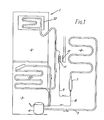
- the appliance is shown generally at 1 and includes a refrigerator compartment 2.and a freezer compartment 3.
- a single compressor 4 drives a suitable coolant medium of known kind via a pipe 5 to a condenser 6 and a drier 7, at the output of which the medium separates into two restrictor tubes, 8 and 9.
- Restrictor tube 8 leads to the evaporator 10 associated with the freezer compartment 3 and thence back to the input of compressor 4.
- Restrictor tube 9 leads to the evaporator 12 associated with the refrigerator compartment 2.
- the medium, having traversed the evaporator 12 is constrained to pass through the evaporator 10 before returning to the compressor 4.
- Portion 11 of the restrictor tube 9 is wound around a control heater 13 for reasons that will become clear hereinafter.
- Both compartments 2 and 3 have respective thermostats (not shown in Figure 1) to permit the temperatures of the two compartments to be selected by the user.
- the freezer themostat is, however, caused to be the main control and this generates an electrical signal which starts the compressor 4 when refrigeration is required in the freezer compartment 3.
- the refrigerator compartment 2 will also be cooled until the refrigerator thermostat (which is of the changeover kind) produces an electrical signal indicating that the relevant compartment (2) is cold enough.
- the control heater 13 is energised and induces a phase change in the refrigerant material flowing through the portion 11 of the restrictor tube 9, changing the material from liquid to vapour. The mass flow rate is reduced dramatically when this phase change occurs, effectively eliminating cooling of the refrigerator compartment 2.
- the heater continues to be energised until the refrigerator thermostat generates a signal indicating that further cooling of the relevant compartment (2) is required. At that time the heater 13 is de-energised and cooling re-commences.
- the arrangement is such that the refrigerator thermostat can re-start the compressor should the refrigerator compartment temperature exceed that set by the thermostat associated with the relevant compartment (2). Under these circumstances, it will be appreciated that the freezer compartment 3 will be cooled to an extent slightly greater than that set by its thermostat.
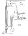
- Thermostat 15 the main device, is effective to start the compressor 4 when the temperature in the freezer compartment exceeds that set on the thermostat 15 by means of a user-operable control.
- the compressor having been activated, both compartments 2 and 3 are cooled, and let us assume that compartment 2 is the first to be cooled to the temperature set by its associated thermostat 14.
- the thermostat 14 changes from position C to position B, which thus energises the heater 13 via a normally closed switch 18 which is opened when a temperature detector 19, of any convenient form, detects that the temperature in the vicinity of the heater 13 is, or is in danger of, exceeding a safe limit set by the detector itself.
- the detector 19 is typically a bimetallic thermal cut-out device and the switch 18 may be integral therewith or separate and controlled thereby.
- the thermostat 14 When the temperature within the refrigerator compartment 2 has risen to above the temperature set by the thermostat 14, then the thermostat 14 reverts to position C, thereby de-energising the heater 13 and also ensuring that the compressor 4 is turned on, even if the freezer thermostat 15 has caused the compressor 4 to be turned off due to the freezer compartment 3 having reached the set temperature therefor.
- Switch 20 may be arranged to energise a neon light 21 situated within the refrigerator compartment 2, whenever the door thereto is opened.
Landscapes
- Engineering & Computer Science (AREA)
- Physics & Mathematics (AREA)
- General Physics & Mathematics (AREA)
- Automation & Control Theory (AREA)
- Mechanical Engineering (AREA)
- Thermal Sciences (AREA)
- General Engineering & Computer Science (AREA)
- Devices That Are Associated With Refrigeration Equipment (AREA)
Applications Claiming Priority (2)
| Application Number | Priority Date | Filing Date | Title |
|---|---|---|---|
| GB8321283 | 1983-08-06 | ||
| GB838321283A GB8321283D0 (en) | 1983-08-06 | 1983-08-06 | Domestic electrical appliances |
Publications (2)
| Publication Number | Publication Date |
|---|---|
| EP0134641A2 true EP0134641A2 (de) | 1985-03-20 |
| EP0134641A3 EP0134641A3 (de) | 1986-08-13 |
Family
ID=10546966
Family Applications (1)
| Application Number | Title | Priority Date | Filing Date |
|---|---|---|---|
| EP84304449A Withdrawn EP0134641A3 (de) | 1983-08-06 | 1984-06-29 | Kühlungssteuerungssystem |
Country Status (4)
| Country | Link |
|---|---|
| EP (1) | EP0134641A3 (de) |
| DK (1) | DK379484A (de) |
| ES (1) | ES8505780A1 (de) |
| GB (1) | GB8321283D0 (de) |
Family Cites Families (4)
| Publication number | Priority date | Publication date | Assignee | Title |
|---|---|---|---|---|
| DE1151261B (de) * | 1957-07-01 | 1963-07-11 | Electrolux Ab | Vorrichtung bei einem Kuehlschrank zur Regelung der Temperatur einer Kuehl-kammer unabhaengig von den Temperaturen in den uebrigen Kuehlkammern |
| DE1941495A1 (de) * | 1968-09-27 | 1970-04-09 | Hitachi Ltd | Kuehlgeraet |
| CA1046784A (en) * | 1975-11-28 | 1979-01-23 | Bent Karll | Compressor refrigeration plant |
| IT1111778B (it) * | 1979-01-22 | 1986-01-13 | Philco Italiana | Macchina frigo-congelatrice a compressore unico |
-
1983
- 1983-08-06 GB GB838321283A patent/GB8321283D0/en active Pending
-
1984
- 1984-06-29 EP EP84304449A patent/EP0134641A3/de not_active Withdrawn
- 1984-08-06 DK DK379484A patent/DK379484A/da not_active Application Discontinuation
- 1984-08-06 ES ES534911A patent/ES8505780A1/es not_active Expired
Also Published As
| Publication number | Publication date |
|---|---|
| ES534911A0 (es) | 1985-06-01 |
| DK379484A (da) | 1985-02-07 |
| GB8321283D0 (en) | 1983-09-07 |
| DK379484D0 (da) | 1984-08-06 |
| ES8505780A1 (es) | 1985-06-01 |
| EP0134641A3 (de) | 1986-08-13 |
Similar Documents
| Publication | Publication Date | Title |
|---|---|---|
| KR900008901B1 (ko) | 차량의 공기조화기 및 냉장고의 냉각장치 | |
| US2812642A (en) | Refrigerating apparatus | |
| US3218819A (en) | Refrigeration apparatus | |
| US3004401A (en) | Forced air cooled refrigerator | |
| US2713249A (en) | Liquid defrosting system and the like | |
| US3135316A (en) | Convertible heating and cooling food storage cabinet | |
| US3023589A (en) | Refrigerating apparatus | |
| US2462240A (en) | Two-temperature refrigerator system | |
| US3174297A (en) | Refrigerating apparatus with defrost control means | |
| US2133948A (en) | Refrigeration apparatus | |
| US3123986A (en) | Combined refrigerator | |
| US3010288A (en) | Refrigerating apparatus | |
| US2551163A (en) | Refrigerating apparatus | |
| US3164970A (en) | Defrost control | |
| EP0045728A2 (de) | Elektronischer Temperaturregler für ein Gefriergerät | |
| US2723533A (en) | Refrigerating apparatus | |
| US2947153A (en) | Combined thermostat and defrost control for air conditioning apparatus | |
| US2065604A (en) | Refrigerating apparatus | |
| US3063250A (en) | Refrigeration apparatus with defrost control means | |
| US2962872A (en) | Refrigerator construction and controls | |
| US2805555A (en) | Hot gas defrost system | |
| US4178771A (en) | Compressor refrigerator | |
| EP0134641A2 (de) | Kühlungssteuerungssystem | |
| US2133955A (en) | Control for two-temperature refrigerators | |
| US2733574A (en) | Refrigerating system |
Legal Events
| Date | Code | Title | Description |
|---|---|---|---|
| PUAI | Public reference made under article 153(3) epc to a published international application that has entered the european phase |
Free format text: ORIGINAL CODE: 0009012 |
|
| AK | Designated contracting states |
Designated state(s): AT BE CH DE FR GB IT LI LU NL SE |
|
| RAP1 | Party data changed (applicant data changed or rights of an application transferred) |
Owner name: THORN EMI APPLIANCES LIMITED |
|
| PUAL | Search report despatched |
Free format text: ORIGINAL CODE: 0009013 |
|
| AK | Designated contracting states |
Kind code of ref document: A3 Designated state(s): AT BE CH DE FR GB IT LI LU NL SE |
|
| STAA | Information on the status of an ep patent application or granted ep patent |
Free format text: STATUS: THE APPLICATION IS DEEMED TO BE WITHDRAWN |
|
| 18D | Application deemed to be withdrawn |
Effective date: 19870216 |
|
| RIN1 | Information on inventor provided before grant (corrected) |
Inventor name: MILLS, ALAN CHARLES Inventor name: SHONE, KENNETH ARTHUR |