EP0134639A2 - Knock down containers - Google Patents
Knock down containers Download PDFInfo
- Publication number
- EP0134639A2 EP0134639A2 EP84304432A EP84304432A EP0134639A2 EP 0134639 A2 EP0134639 A2 EP 0134639A2 EP 84304432 A EP84304432 A EP 84304432A EP 84304432 A EP84304432 A EP 84304432A EP 0134639 A2 EP0134639 A2 EP 0134639A2
- Authority
- EP
- European Patent Office
- Prior art keywords
- container
- panels
- panel
- bracket
- clips
- Prior art date
- Legal status (The legal status is an assumption and is not a legal conclusion. Google has not performed a legal analysis and makes no representation as to the accuracy of the status listed.)
- Withdrawn
Links
- 238000003197 gene knockdown Methods 0.000 title claims abstract description 6
- 229920003023 plastic Polymers 0.000 claims description 7
- 239000004033 plastic Substances 0.000 claims description 7
- 239000004743 Polypropylene Substances 0.000 claims description 2
- 238000000034 method Methods 0.000 claims description 2
- -1 polypropylene Polymers 0.000 claims description 2
- 229920001155 polypropylene Polymers 0.000 claims description 2
- 239000000758 substrate Substances 0.000 claims 1
- 239000002184 metal Substances 0.000 description 2
- 230000000295 complement effect Effects 0.000 description 1
- 238000000465 moulding Methods 0.000 description 1
- 230000003014 reinforcing effect Effects 0.000 description 1
- 229920003002 synthetic resin Polymers 0.000 description 1
- 239000000057 synthetic resin Substances 0.000 description 1
- 235000013311 vegetables Nutrition 0.000 description 1
- 125000000391 vinyl group Chemical group [H]C([*])=C([H])[H] 0.000 description 1
- 229920002554 vinyl polymer Polymers 0.000 description 1
Images

Classifications
-
- A—HUMAN NECESSITIES
- A47—FURNITURE; DOMESTIC ARTICLES OR APPLIANCES; COFFEE MILLS; SPICE MILLS; SUCTION CLEANERS IN GENERAL
- A47F—SPECIAL FURNITURE, FITTINGS, OR ACCESSORIES FOR SHOPS, STOREHOUSES, BARS, RESTAURANTS OR THE LIKE; PAYING COUNTERS
- A47F5/00—Show stands, hangers, or shelves characterised by their constructional features
- A47F5/10—Adjustable or foldable or dismountable display stands
- A47F5/13—Adjustable or foldable or dismountable display stands made of tubes or wire
-
- F—MECHANICAL ENGINEERING; LIGHTING; HEATING; WEAPONS; BLASTING
- F16—ENGINEERING ELEMENTS AND UNITS; GENERAL MEASURES FOR PRODUCING AND MAINTAINING EFFECTIVE FUNCTIONING OF MACHINES OR INSTALLATIONS; THERMAL INSULATION IN GENERAL
- F16B—DEVICES FOR FASTENING OR SECURING CONSTRUCTIONAL ELEMENTS OR MACHINE PARTS TOGETHER, e.g. NAILS, BOLTS, CIRCLIPS, CLAMPS, CLIPS OR WEDGES; JOINTS OR JOINTING
- F16B12/00—Jointing of furniture or the like, e.g. hidden from exterior
- F16B12/10—Jointing of furniture or the like, e.g. hidden from exterior using pegs, bolts, tenons, clamps, clips, or the like
- F16B12/28—Jointing of furniture or the like, e.g. hidden from exterior using pegs, bolts, tenons, clamps, clips, or the like for metal furniture parts
- F16B12/38—Jointing of furniture or the like, e.g. hidden from exterior using pegs, bolts, tenons, clamps, clips, or the like for metal furniture parts using snap-action elements
-
- Y—GENERAL TAGGING OF NEW TECHNOLOGICAL DEVELOPMENTS; GENERAL TAGGING OF CROSS-SECTIONAL TECHNOLOGIES SPANNING OVER SEVERAL SECTIONS OF THE IPC; TECHNICAL SUBJECTS COVERED BY FORMER USPC CROSS-REFERENCE ART COLLECTIONS [XRACs] AND DIGESTS
- Y10—TECHNICAL SUBJECTS COVERED BY FORMER USPC
- Y10T—TECHNICAL SUBJECTS COVERED BY FORMER US CLASSIFICATION
- Y10T24/00—Buckles, buttons, clasps, etc.
- Y10T24/34—Combined diverse multipart fasteners
- Y10T24/3427—Clasp
- Y10T24/3439—Plural clasps
- Y10T24/344—Resilient type clasp
-
- Y—GENERAL TAGGING OF NEW TECHNOLOGICAL DEVELOPMENTS; GENERAL TAGGING OF CROSS-SECTIONAL TECHNOLOGIES SPANNING OVER SEVERAL SECTIONS OF THE IPC; TECHNICAL SUBJECTS COVERED BY FORMER USPC CROSS-REFERENCE ART COLLECTIONS [XRACs] AND DIGESTS
- Y10—TECHNICAL SUBJECTS COVERED BY FORMER USPC
- Y10T—TECHNICAL SUBJECTS COVERED BY FORMER US CLASSIFICATION
- Y10T403/00—Joints and connections
- Y10T403/71—Rod side to plate or side
- Y10T403/7129—Laterally spaced rods
- Y10T403/7141—Plural channels in connector
Definitions
- the invention relates to knock down containers for storing or transporting items such as clothes, housewares, tools, vegetable produce, etc. It is well known that one can buy so-called knock down furniture comprising a kit of parts which are assembled by user to form a predetermined storage container or display unit, see e.g. U.S. patents 1648025A, 3208406A and 3693808A.
- a difficulty with known containers is that because the components are arranged to interengage in a predetermined way only, the user cannot easily use the components to assemble a container of a different configuration. Also, very often the components must be engaged using tools. In general, the known containers must be stood on a support, e.g. connected to a bracket on the floor. It is one object of this invention to provide a container for storage or transport which may readily be assembled on site to any configuration without the use of tools, and which may be dismantled and assembled in a different configuration at the choice of the user. It is another object of the invention to provide a storage container which may be suspended from a support, e.g. an overhead rail as in a wardrobe clothes rail, and also to provide a range of brackets useful for this and allied purposes.
- a container in knock down form comprising a kit of parts to be assembled into the container, the kit including container wall panels having engaging parts whereby the panels are held together characterised in that the margins of the panels (P) are of rod form (R) and in-that separates clips (C) are present to connect the panels (P) together, the clips having two generally parallel channels (11) each to receive a panel margin (R).
- rod is intended to embrace any cylindrical item, e.g. a rod, bar, tube or the like and which may be of circular or substantially circular cross-sectional shape or other shape which can be engaged with the separate clips having complementary shaped channels.
- the container may take the form of a bin, box, compartment having all closed sides or at least one open side.
- the panels and the clips are formed of synthetic resin, however the panels may be vinyl coated wire.
- each clip comprises an elongate body of generally E cross sectional shape, the outer walls being rounded and the web between the channels being shorter and thinner than the outer walls.
- the invention includes a range of brackets, each having a channel like socket to receive a rod of a panel, and engaging means to engage a support from which the container may be suspended or which is suspended from the container or to engage a structure.
- each bin comprises a number of panels P, namely, a bottom panel Pl, two side panels P2, and a back panel P3.
- Each panel is a planar generally square grid like structure, the vertical and horizontal bars and margins of which are formed of rods R of circular cross-sectional shape.
- the panels are formed of strong resilient plastics such as polypropylene, metal, plastics coated metal or the like. Adjacent panels are held together at their edges by clips C.
- Each clip is moulded of plastics and is of generally E cross-sectional shape, having two identical channels 11.
- the length of the clip is equal to the distance between adjacent rods R of the panel.
- each channel 11 has an outer wall 12 having a rounded top surface 13, and the channels are separated by a relatively thinner and shorter web 14.
- the mouth of the channels is slightly smaller than the channel itself.
- Each channel 11 is dimensioned to receive and engage a rod R of a panel, the rod being guided into the channel by urging outwardly the outer wall, and the rod is received in the channel as a snap fit. Although the rod R is received in a channel 11 and held snugly therein, the rod may still be pivoted with respect to the channel, which facilitates assembly of the bin.
- a kit of parts is supplied to the user to snap engage clips C to the margins R on three sides of one panel destined to be the bottom panel Pl.
- the panel Pl is laid flat on say a table or floor surface and then the margin of a panel-is snap fitted to the outer channel 11 of each clip C already secured to the bottom panel Pl).
- Two adjacent panels P2, P3 are then raised vertically and clipped together at their margins.
- the third panel P2 is raised and clipped to the adjacent one. It has been found preferable to engage each corner of a bin by the use of two clips C spaced apart along the margin of the panels. If the bin is to have four sides the process is repeated for the fifth panel.
- Bins may be connected together by engaging the clips C with panel margins of adjacent bins.
- the top bin is connected to the clothes hanger rail 10 by a bracket B1 of generally U shape.
- the ,bight 15 of the bracket is shaped to straddle and engage the circular rail 10 and the free ends of the bracket Bl are each shaped as a clip 16 having a single channel 11 with a thickened base 17 and relatively thin sidewalls 18 ( Figure 4) to engage a pair of the grid rods R of a panel as a snap fit.
- two brackets Bl hold the top bin to the rail 10.
- the bins contain folded towels or blankets. Because the panels have open sides clothes stored in the bins are well ventilated. It is surprising how much weight can be put in the bins without the panels or clips distorting, even though they are plastics mouldings. Up to 10 kg can be placed in a bin measuring 30 cm x 30 cm x 30 cm.
- a bracket Bl is used in association with a bracket B2 to suspend a tubular rod 19, e.g. for hanging towels, face cloths or neck ties below bins.
- the bracket Bl is inverted and connected to a side panel P2 of the bin Sl by engagement of the clips 16 at the free ends with adjacent rods R of the grid.
- the bracket B2 is adapted to engage a side panel P2 of another bin S2 located alongside and below the level of the first bin.
- the bracket B2 comprises a base 20 having a foot 21.
- a channel shape 22 is formed in one side in the base and the foot to engage a rod R of the side panel P2 of the bin S2 which is present below and to one side of the first bin Sl.
- An upright wall 23 stands on the base 20 and has a reinforcing sloped rib 24 and another 25 extends between the underside of the base 20 and the foot 21.
- the tube 19 has two longitudinally spaced apart recesses 26, one to receive the wall 23 in snug engagement and the other to receive the bight 15 of the bracket B2.
- the brackets are dimensioned so that the tube 19 will be suspended generally horizontally below the bins.
- the bracket B2 is snap fitted to an upright rod R of the adjacent panel P2, and the tube 19 is brought to engage the wall 23 in one of the recesses 26.
- the bracket B1 is snap fitted to the opposite panel P2 of the first bin, and the bight 15 is received in the adjacent recess 26.
- the rib 24 helps keep the bracket B2 and the rod 19 in engagement.
- brackets Bl two bins having a common wall are secured in side-by-side relation and both are suspended from a rail 10 by three brackets Bl.
- a rod 19 is suspended below one bin S, the right hand bin, as shown, by a pair of brackets B3, shown in more detail in Figure 9.
- the bracket B3 comprises a channel section 11 from one end of which extends an offset portion 27, shaped and dimensioned to engage the rods R at the corner of a bin, and which has an extension 28 which extends in a loop portion 29.
- a pair of brackets B3 is suspended from opposite sides of the bin by snap fitting the channel section into. engagement with a vertical rod R, the adjacent horizontal rod (or rods) being received in the portion 27.
- a rod 19 is fitted to the brackets B3 by urging it down on to the loop portions 29, until they are received in the respective recess 26.
- a dimple 30 is present on the outside of the loop portion 29 better to engage the parts together, and as-shown in Figure 10.
- a bracket B4 is used to steady a bin (or bins) to an adjacent wall 31.
- the bracket B4 has a base 32 having a channel 11 to receive a rod R of a panel P.
- the channel has a thicker side wall 33 having an overhang 34 and a thin opposite sidewall 35.
- the bracket B4 is secured to the wall 31 by a screw passed through a screwhole 36.
- a number of the brackets B4 may be used to secure a bin to a wall 31, in the absence of the rail 10, e.g. to make use of a blank wall.
- a carrying basket may be built up of a bottom panel Pl and four side panels P2, and attaching a rod 19 to two opposite sides P2 by brackets B2 to define a carrying handle.
- the bin may be used for this purpose, e.g. for tools or toys.
- bracket B5 is used to suspend a bin from a wire shelf 37.
- the bracket B5 comprises a web 38 having at each end an open loop 39, 40, one of which is of a larger diameter than the other.
- the loop 40 is looped over a rod R and then the loop 39 is looped over a wire of the shelf 37.
- the user is able to make from the kit of parts any shape of container that he wants and to dismantle that shape and build up another, all by hand.
- the container may be suspended from a wall both inside and outside and which may be fixed or movable, e.g. a closet interior wall or an office door.
- the kit of parts is light in weight and of low volume when collapsed making it eminently suitable for transport and storage.
Landscapes
- Engineering & Computer Science (AREA)
- General Engineering & Computer Science (AREA)
- Mechanical Engineering (AREA)
- Supports Or Holders For Household Use (AREA)
- Assembled Shelves (AREA)
- Packaging Of Annular Or Rod-Shaped Articles, Wearing Apparel, Cassettes, Or The Like (AREA)
Abstract
A container in knock down form is especially easy to assemble, dismantle and reassemble, comprises a kit of panels (P) and clips (C), the panels having marginal rods (R) and the clips (C) being of generally E form and having two channels (11) each to receive a margin (R). Preferably the containers are suspended from a rod (10) e.g. a coat hanger rail. A range of brackets B1, B2, B3, B4, B5 to secure the container parts together or to a support is also disclosed.
Description
- The invention relates to knock down containers for storing or transporting items such as clothes, housewares, tools, vegetable produce, etc. It is well known that one can buy so-called knock down furniture comprising a kit of parts which are assembled by user to form a predetermined storage container or display unit, see e.g. U.S. patents 1648025A, 3208406A and 3693808A.
- A difficulty with known containers is that because the components are arranged to interengage in a predetermined way only, the user cannot easily use the components to assemble a container of a different configuration. Also, very often the components must be engaged using tools. In general, the known containers must be stood on a support, e.g. connected to a bracket on the floor. It is one object of this invention to provide a container for storage or transport which may readily be assembled on site to any configuration without the use of tools, and which may be dismantled and assembled in a different configuration at the choice of the user. It is another object of the invention to provide a storage container which may be suspended from a support, e.g. an overhead rail as in a wardrobe clothes rail, and also to provide a range of brackets useful for this and allied purposes.
- According to one aspect of the invention there is provided a container in knock down form, comprising a kit of parts to be assembled into the container, the kit including container wall panels having engaging parts whereby the panels are held together characterised in that the margins of the panels (P) are of rod form (R) and in-that separates clips (C) are present to connect the panels (P) together, the clips having two generally parallel channels (11) each to receive a panel margin (R).
- The term "rod" is intended to embrace any cylindrical item, e.g. a rod, bar, tube or the like and which may be of circular or substantially circular cross-sectional shape or other shape which can be engaged with the separate clips having complementary shaped channels.
- The container may take the form of a bin, box, compartment having all closed sides or at least one open side.
- Most preferably the panels and the clips are formed of synthetic resin, however the panels may be vinyl coated wire.
- In a much preferred feature, the panels are of grid form, the bars of the grid being of the same rod form as the margins of the panels. It is preferred that the length of the clips is substantially equal to the distance between adjacent parallel bars of the grid. Preferably, each clip comprises an elongate body of generally E cross sectional shape, the outer walls being rounded and the web between the channels being shorter and thinner than the outer walls.
- In a much preferred feature, the invention includes a range of brackets, each having a channel like socket to receive a rod of a panel, and engaging means to engage a support from which the container may be suspended or which is suspended from the container or to engage a structure.
- In order that the invention may be well understood, it will now be described with reference to the accompanying diagrammatic drawings, in which
- Figure 1 is a perspective view of a stack of storage bins of the invention;
- Figure 2 is a perspective view drawn to an enlarged scale of a corner of the bin of Figure 1;
- Figure 3 is a sectional view taken on lines III-III on Figure 1;
- Figure 4 is a sectional view taken on lines IV-IV on Figure 1;
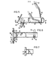
- Figure 5 is a perspective view of a rod for neck ties, etc. to be suspended by brackets below a bin;
- Figure 6 is a section taken on lines VI-VI on Figure 5;
- Figure 7 is a section taken on lines VII-VII on Figure 6;
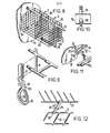
- Figure 8 is another embodiment of the invention;
- Figures 9, 10 and 11 show details of the embodiment of Figure 8, and
- Figure 12 shows a bin suspended by a bracket from a wire shelf.
- Where possible-the same reference numerals are used in the different embodiments.
- The embodiment of Figures 1 to 4 comprises a stack or column of open storage bins or baskets S located in a wardrobe or cubicle, the top bin being suspended from the
rail 10 of circular cross-section which may be a coat hanger rail or a shower curtain rail, etc. As shown, each bin comprises a number of panels P, namely, a bottom panel Pl, two side panels P2, and a back panel P3. Each panel is a planar generally square grid like structure, the vertical and horizontal bars and margins of which are formed of rods R of circular cross-sectional shape. The panels are formed of strong resilient plastics such as polypropylene, metal, plastics coated metal or the like. Adjacent panels are held together at their edges by clips C. Each clip is moulded of plastics and is of generally E cross-sectional shape, having twoidentical channels 11. The length of the clip is equal to the distance between adjacent rods R of the panel. As shown in Figure 3, eachchannel 11 has anouter wall 12 having a rounded top surface 13, and the channels are separated by a relatively thinner and shorter web 14. The mouth of the channels is slightly smaller than the channel itself. Eachchannel 11 is dimensioned to receive and engage a rod R of a panel, the rod being guided into the channel by urging outwardly the outer wall, and the rod is received in the channel as a snap fit. Although the rod R is received in achannel 11 and held snugly therein, the rod may still be pivoted with respect to the channel, which facilitates assembly of the bin. A kit of parts is supplied to the user to snap engage clips C to the margins R on three sides of one panel destined to be the bottom panel Pl. (In one convenient operation the panel Pl is laid flat on say a table or floor surface and then the margin of a panel-is snap fitted to theouter channel 11 of each clip C already secured to the bottom panel Pl). Two adjacent panels P2, P3 are then raised vertically and clipped together at their margins. The third panel P2 is raised and clipped to the adjacent one. It has been found preferable to engage each corner of a bin by the use of two clips C spaced apart along the margin of the panels. If the bin is to have four sides the process is repeated for the fifth panel. - Bins may be connected together by engaging the clips C with panel margins of adjacent bins.
- The top bin is connected to the
clothes hanger rail 10 by a bracket B1 of generally U shape. The ,bight 15 of the bracket is shaped to straddle and engage thecircular rail 10 and the free ends of the bracket Bl are each shaped as aclip 16 having asingle channel 11 with a thickened base 17 and relatively thin sidewalls 18 (Figure 4) to engage a pair of the grid rods R of a panel as a snap fit. As shown in Figure 1, two brackets Bl hold the top bin to therail 10. In Figure'1, the bins contain folded towels or blankets. Because the panels have open sides clothes stored in the bins are well ventilated. It is surprising how much weight can be put in the bins without the panels or clips distorting, even though they are plastics mouldings. Up to 10 kg can be placed in a bin measuring 30 cm x 30 cm x 30 cm. - In the embodiment of Figure 5, a bracket Bl is used in association with a bracket B2 to suspend a
tubular rod 19, e.g. for hanging towels, face cloths or neck ties below bins. The bracket Bl is inverted and connected to a side panel P2 of the bin Sl by engagement of theclips 16 at the free ends with adjacent rods R of the grid. The bracket B2 is adapted to engage a side panel P2 of another bin S2 located alongside and below the level of the first bin. The bracket B2 comprises abase 20 having afoot 21. Achannel shape 22 is formed in one side in the base and the foot to engage a rod R of the side panel P2 of the bin S2 which is present below and to one side of the first bin Sl. Anupright wall 23 stands on thebase 20 and has a reinforcingsloped rib 24 and another 25 extends between the underside of thebase 20 and thefoot 21. Thetube 19 has two longitudinally spaced apartrecesses 26, one to receive thewall 23 in snug engagement and the other to receive thebight 15 of the bracket B2. The brackets are dimensioned so that thetube 19 will be suspended generally horizontally below the bins. In use, the bracket B2 is snap fitted to an upright rod R of the adjacent panel P2, and thetube 19 is brought to engage thewall 23 in one of therecesses 26. The bracket B1 is snap fitted to the opposite panel P2 of the first bin, and thebight 15 is received in theadjacent recess 26. Therib 24 helps keep the bracket B2 and therod 19 in engagement. - In the embodiment of Figure 8, two bins having a common wall are secured in side-by-side relation and both are suspended from a
rail 10 by three brackets Bl. Arod 19 is suspended below one bin S, the right hand bin, as shown, by a pair of brackets B3, shown in more detail in Figure 9. The bracket B3 comprises achannel section 11 from one end of which extends anoffset portion 27, shaped and dimensioned to engage the rods R at the corner of a bin, and which has anextension 28 which extends in aloop portion 29. A pair of brackets B3 is suspended from opposite sides of the bin by snap fitting the channel section into. engagement with a vertical rod R, the adjacent horizontal rod (or rods) being received in theportion 27. Arod 19 is fitted to the brackets B3 by urging it down on to theloop portions 29, until they are received in therespective recess 26. Adimple 30 is present on the outside of theloop portion 29 better to engage the parts together, and as-shown in Figure 10. - A bracket B4 is used to steady a bin (or bins) to an
adjacent wall 31. The bracket B4 has a base 32 having achannel 11 to receive a rod R of a panel P. The channel has a thicker side wall 33 having anoverhang 34 and a thinopposite sidewall 35. The bracket B4 is secured to thewall 31 by a screw passed through ascrewhole 36. A number of the brackets B4 may be used to secure a bin to awall 31, in the absence of therail 10, e.g. to make use of a blank wall. - It will be appreciated that a carrying basket may be built up of a bottom panel Pl and four side panels P2, and attaching a
rod 19 to two opposite sides P2 by brackets B2 to define a carrying handle. The bin may be used for this purpose, e.g. for tools or toys. - In the embodiment of Figure 12, a number of spaced apart brackets B5 is used to suspend a bin from a
wire shelf 37. The bracket B5 comprises aweb 38 having at each end anopen loop 39, 40, one of which is of a larger diameter than the other. In use, theloop 40 is looped over a rod R and then the loop 39 is looped over a wire of theshelf 37. - By virtue of the invention, the user is able to make from the kit of parts any shape of container that he wants and to dismantle that shape and build up another, all by hand. The container may be suspended from a wall both inside and outside and which may be fixed or movable, e.g. a closet interior wall or an office door. The kit of parts is light in weight and of low volume when collapsed making it eminently suitable for transport and storage.
Claims (11)
1. A container in knock down form, comprising a kit of parts to be assembled into the container, the kit including container wall panels having engaging parts whereby the panels are held together characterised in that the margins of the panels (P) are of rod form (R) and in that separate clips (C) are present to connect the panels (P) together, the clips having two generally parallel channels (11) each to receive a panel margin (R).
2. A container kit according to Claim 1 characterised in that the panels (P) are of grid form, the bars of the grid being of the same rod form (R) as the margins of the panels.
3. A container kit according to Claim 2 characterised in that the length of the clips (C) is substantially equal to the distance between adjacent parallel bars (R) of the grid.
4. A container kit according to any preceding Claim characterised in that each clip comprises an elongate body of generally E cross sectional shape, having two parallel channels (11), the outer walls (12) being rounded (13) and the web (14) between the channels being shorter and thinner than the outer walls (11).
5. A container kit according to Claim 4 characterised in that the diameter of the channels (11) is selected relative to the diameter of the rods (R) at the margins of the panels (P) so that the parts are engaged as a snap fit and the margin of a panel may be pivotally moved within the respective channel.
6. A container kit according to any preceding Claim characterised in that a bracket (Bl) is present to suspend the container from a cylindrical support mounted overhead, e.g. a clothes hanger rail (10), the bracket (Bl) being of generally U shape with the bight (15) being adapted to engage the support (10) and each free arm being of clip form (16) having a single channel (11) whereby the bracket (Bl) may be engaged with two rods (R) of a panel (P).
7. A container kit according to any preceding Claim characterised in that a bracket (B2, B3) is present to engage the container with a cylindrical rod (19) which is not a support, and in that the bracket (B2, B3) comprises a clip portion having a channel (11, 22) to be engaged with a rod (R) of a panel (P) and a connecting portion (23,29) to engage the rod (19).
8. A container kit according to Claim 7 characterised in that the connecting part (23, 29) of the bracket (B2, B3) is adapted to be received in and engaged with recesses (26) preformed in the rod (19).
9. A container kit according to any preceding Claim characterised in that the kit includes bracket (B4, B5) having a portion (11, 40) for a connection to a panel (P) of the container and a portion (36, 39) to engage a structure (31, 37).
10. A container kit according to any preceding Claim characterised in that the clips (C) and the brackets (B) are formed of a strong resilient plastics such as polypropylene and the panels (P) are formed of such plastics or a plastics coated wire.
11. A method of assembling a container according to any of Claims 1 to 5 characterised in that clips are engaged with at least three opposite sides of a first panel, the panel is laid flat on a substrate, e.g. a table or floor, three other panels are then engaged with the clips of the first panel, and a pair of the other panels is then raised and clipped together, followed by the raising of the third other panel and clipping that to one of the other panels to form the container.
Applications Claiming Priority (4)
| Application Number | Priority Date | Filing Date | Title |
|---|---|---|---|
| US51228583A | 1983-07-08 | 1983-07-08 | |
| US512285 | 1983-07-08 | ||
| US06/573,989 US4765495A (en) | 1983-07-08 | 1984-01-26 | Knock down storage system and accessories therefor |
| US573989 | 2000-05-17 |
Publications (2)
| Publication Number | Publication Date |
|---|---|
| EP0134639A2 true EP0134639A2 (en) | 1985-03-20 |
| EP0134639A3 EP0134639A3 (en) | 1985-07-31 |
Family
ID=27057515
Family Applications (1)
| Application Number | Title | Priority Date | Filing Date |
|---|---|---|---|
| EP84304432A Withdrawn EP0134639A3 (en) | 1983-07-08 | 1984-06-28 | Knock down containers |
Country Status (2)
| Country | Link |
|---|---|
| US (1) | US4765495A (en) |
| EP (1) | EP0134639A3 (en) |
Cited By (2)
| Publication number | Priority date | Publication date | Assignee | Title |
|---|---|---|---|---|
| EP0291058A1 (en) * | 1987-05-14 | 1988-11-17 | Mamouth Comix Ltd. | System for assembling furniture, boxes, partitions or the like |
| WO1993019641A1 (en) * | 1992-04-01 | 1993-10-14 | O Seop Shin | Instant furniture for household effects |
Families Citing this family (42)
| Publication number | Priority date | Publication date | Assignee | Title |
|---|---|---|---|---|
| US5058863A (en) * | 1988-09-15 | 1991-10-22 | Maffet Harold C | Panel apparatus and elements for securing a plurality of panels together |
| ZA89620B (en) * | 1989-01-26 | 1990-02-28 | Fridjhon Michael | Wine rack |
| US5069350A (en) * | 1989-11-28 | 1991-12-03 | Wood-Mode, Incorporated | Backsplash system |
| USD334704S (en) | 1991-06-10 | 1993-04-13 | Rubbermaid Commercial Products Inc. | Connector for receptacles |
| US5331725A (en) * | 1992-07-30 | 1994-07-26 | Design Ideas, Ltd. | Rod clip |
| US5383562A (en) * | 1992-12-21 | 1995-01-24 | Gay; Kenneth F. | Open frame rack assembly |
| US5727700A (en) * | 1995-02-28 | 1998-03-17 | American Greetings Corporation | Overhead display unit for inflated balloons |
| US5749479A (en) * | 1996-01-18 | 1998-05-12 | Belokin; Paul | Display assembly |
| USD382747S (en) * | 1996-04-02 | 1997-08-26 | Contico International, Inc. | Hanging closet organizer |
| US6161320A (en) * | 1997-07-02 | 2000-12-19 | Peterson; Steven Charles | Portable, modular, graphics-display system |
| DE19815047B4 (en) * | 1997-09-24 | 2006-08-17 | Obo Bettermann Gmbh & Co. Kg | Arrangement for the screwless connection of grid cable tracks |
| US6581786B1 (en) * | 1998-02-17 | 2003-06-24 | Industrial Wire Products, Inc Missouri Corp. | Suspended shoe rack |
| USD429938S (en) * | 1998-09-03 | 2000-08-29 | Allen Eric L | Locker door storage rack |
| US6019445A (en) * | 1999-01-15 | 2000-02-01 | Gades; Blair R. | Multiple compartment laundry sorter |
| US6669036B1 (en) * | 1999-10-13 | 2003-12-30 | Frank Yang | Modular storage assembly |
| IT1316165B1 (en) * | 2000-01-11 | 2003-04-03 | Metaltex Spa | METAL WIRE SHELF WITH SUSPENSIBLE SIDES, PARTICULARLY FOR TROLLEYS AND SIMILAR |
| USD435990S1 (en) | 2000-01-24 | 2001-01-09 | Sandy Alan Felsenthal | Hanging drawer set |
| USD435378S (en) * | 2000-01-24 | 2000-12-26 | Sandy Alan Felsenthal | Hanging drawer set |
| US6308837B1 (en) * | 2000-02-22 | 2001-10-30 | Elizabeth A. Bragg | Rack for holding pillows |
| US6558065B2 (en) * | 2001-07-09 | 2003-05-06 | Te-Li Huang | Geometric construction system |
| US6823999B2 (en) | 2001-08-10 | 2004-11-30 | William R. Heneveld, Sr. | Pivoting storage organizer bracket system |
| US7244498B2 (en) * | 2002-06-12 | 2007-07-17 | Tda Research, Inc. | Nanoparticles modified with multiple organic acids |
| US6988628B2 (en) * | 2002-09-25 | 2006-01-24 | Sauder Woodworking Company | Closet storage system |
| US7051885B2 (en) | 2003-04-07 | 2006-05-30 | Displays By Martin Paul, Inc. - Creative Center | Cross-merchandising display shelf |
| USD516359S1 (en) | 2004-03-26 | 2006-03-07 | Display By Martin Paul, Inc. - Creative Center | Display shelf with curvature |
| US8443991B1 (en) * | 2006-05-21 | 2013-05-21 | Ellis Ivey, III | Retractable overhead, self-leveling storage assembly |
| US7959019B2 (en) * | 2006-09-14 | 2011-06-14 | Roger Jette | Suspended cable support system |
| US7845080B2 (en) * | 2007-12-26 | 2010-12-07 | Nasiell Gustav M | Tubing cutting apparatus |
| US7967156B2 (en) * | 2008-06-23 | 2011-06-28 | Seville Classics Inc. | Storage rack |
| US20100252520A1 (en) * | 2008-06-23 | 2010-10-07 | Seville Classics, Inc. | Storage rack |
| USD608111S1 (en) | 2009-03-12 | 2010-01-19 | Erie Cotton Products Inc. | Machine-compressed rag dispensing rack |
| US8783628B2 (en) * | 2010-03-26 | 2014-07-22 | Roger Jette | Flexible cable management system |
| US20120132663A1 (en) | 2010-11-30 | 2012-05-31 | Tyco Healthcare Group Lp | Jaw Restraint |
| US20120216375A1 (en) * | 2011-02-24 | 2012-08-30 | Arthur Druhl | Accessory clip for a control bar on a walk behind mower |
| US9072362B2 (en) * | 2011-08-25 | 2015-07-07 | Eric Gallup | Collapsible utility tray with flexible mounting feature |
| ES2395297B1 (en) * | 2011-12-07 | 2014-01-30 | Valdinox, S.L. | DEVICE FOR THE UNION OF PORTABLE TRAY SECTIONS. |
| CA2875573C (en) * | 2013-12-20 | 2020-07-14 | Christine Jacques | Apparatus for drying sporting equipment |
| USD837557S1 (en) * | 2017-03-17 | 2019-01-08 | Whitmor, Inc. | Hanger and storage unit |
| US11013283B2 (en) * | 2017-06-02 | 2021-05-25 | The Hover Cover LLC | Hover cover |
| RU184223U1 (en) * | 2017-09-30 | 2018-10-18 | Дмитрий Андреевич Мельников | QUICK CELL |
| US11525303B2 (en) * | 2019-07-23 | 2022-12-13 | Jackie West | Ceiling tile ladder attachment device |
| IT202000012400A1 (en) * | 2020-05-26 | 2021-11-26 | Ferplast Spa | HOOK ELEMENT FOR THE ASSEMBLY OF CAGES USED FOR THE CONTAINMENT OF PETS |
Family Cites Families (18)
| Publication number | Priority date | Publication date | Assignee | Title |
|---|---|---|---|---|
| FR451728A (en) * | 1912-11-30 | 1913-04-25 | Anton Grabherr | Curtain holder |
| US1225611A (en) * | 1916-04-27 | 1917-05-08 | Edward C Gatlin | Garment-support. |
| GB187685A (en) * | 1921-07-20 | 1922-10-20 | Brier Jenkinson | Improvements in or relating to the displaying or exhibiting of carpets, rugs and the like |
| US1648025A (en) * | 1924-05-26 | 1927-11-08 | Molloy William Lawrence | Display device |
| US1626009A (en) * | 1924-10-21 | 1927-04-26 | Timothy J Murray | Folding crate |
| US1777058A (en) * | 1927-07-27 | 1930-09-30 | Forrest A Walker | Mechanical dishwasher |
| US2480327A (en) * | 1946-01-09 | 1949-08-30 | Idelsohn Rose | Garment hanger |
| US2790556A (en) * | 1954-03-01 | 1957-04-30 | Clinton H Burt | Egg gathering basket |
| FR1173711A (en) * | 1957-04-26 | 1959-03-02 | showcase shelf | |
| US2936146A (en) * | 1957-07-29 | 1960-05-10 | August H Wunder | Detachable supporting rail for receptacles, etc. |
| FR1275250A (en) * | 1960-11-26 | 1961-11-03 | Folding basket with mesh panels | |
| US3208406A (en) * | 1963-05-03 | 1965-09-28 | Maslow Louis | Coupling clip |
| US3693808A (en) * | 1971-06-01 | 1972-09-26 | Brode Milling Co Inc Van | Display rack |
| US3762951A (en) * | 1971-09-08 | 1973-10-02 | Honeywell Inc | Method and apparatus for removing accumulated paint from paint racks |
| US3743106A (en) * | 1972-01-26 | 1973-07-03 | Reliing Corp | Garment hanger device |
| US4136848A (en) * | 1977-02-07 | 1979-01-30 | Mccollum Robert H | Bracket |
| US4319421A (en) * | 1980-05-27 | 1982-03-16 | Sidney Diamond | Ceiling grid suspension display device |
| US4352255A (en) * | 1980-12-04 | 1982-10-05 | Warehime Norwood R | Group use toy structural construction set |
-
1984
- 1984-01-26 US US06/573,989 patent/US4765495A/en not_active Expired - Lifetime
- 1984-06-28 EP EP84304432A patent/EP0134639A3/en not_active Withdrawn
Cited By (2)
| Publication number | Priority date | Publication date | Assignee | Title |
|---|---|---|---|---|
| EP0291058A1 (en) * | 1987-05-14 | 1988-11-17 | Mamouth Comix Ltd. | System for assembling furniture, boxes, partitions or the like |
| WO1993019641A1 (en) * | 1992-04-01 | 1993-10-14 | O Seop Shin | Instant furniture for household effects |
Also Published As
| Publication number | Publication date |
|---|---|
| US4765495A (en) | 1988-08-23 |
| EP0134639A3 (en) | 1985-07-31 |
Similar Documents
| Publication | Publication Date | Title |
|---|---|---|
| EP0134639A2 (en) | Knock down containers | |
| US5289927A (en) | Releasably mountable caddy devices | |
| US4984759A (en) | Container support with improved bag holding means | |
| US5348168A (en) | Releasably mountable caddy devices | |
| US6464086B1 (en) | Hanging modular storage unit | |
| US4760800A (en) | Reversible knick knack shelf | |
| US5620105A (en) | Storage caddy | |
| US20030085188A1 (en) | Hanging storage unit with shelves and hooks | |
| US4895334A (en) | Wall-mountable caddy | |
| CA1255633A (en) | Modular wrap organizer | |
| US6168031B1 (en) | Hanging file support apparatus | |
| KR101804752B1 (en) | Multi-functional rack with wall fixed type | |
| WO2000062650A1 (en) | Funnel system for holding implements | |
| US5472082A (en) | Expandable closet hanger | |
| US6237878B1 (en) | Apparatus for holding a plastic bag | |
| US4915248A (en) | Basket assembly with storage means | |
| US5924578A (en) | Clothing hanger holder | |
| US20240237819A1 (en) | Closet storage system | |
| KR20140112233A (en) | Storage and shelves apparatus installed wall | |
| KR200248922Y1 (en) | Removable shelf partition plate for partitioning the hanging shelf | |
| JPH0468223B2 (en) | ||
| EP0585496A1 (en) | Hanging file system | |
| JPH10179299A (en) | Suspended shelf | |
| KR200464816Y1 (en) | The shelf deferment unit where the establishment is possible in the form which is various | |
| JPH0415112Y2 (en) |
Legal Events
| Date | Code | Title | Description |
|---|---|---|---|
| PUAI | Public reference made under article 153(3) epc to a published international application that has entered the european phase |
Free format text: ORIGINAL CODE: 0009012 |
|
| AK | Designated contracting states |
Designated state(s): AT BE CH DE FR GB IT LI LU NL SE |
|
| PUAL | Search report despatched |
Free format text: ORIGINAL CODE: 0009013 |
|
| AK | Designated contracting states |
Designated state(s): AT BE CH DE FR GB IT LI LU NL SE |
|
| STAA | Information on the status of an ep patent application or granted ep patent |
Free format text: STATUS: THE APPLICATION IS DEEMED TO BE WITHDRAWN |
|
| 18D | Application deemed to be withdrawn |
Effective date: 19860401 |