EP0134231B1 - Fixing element for knocking into a drilled hole - Google Patents
Fixing element for knocking into a drilled hole Download PDFInfo
- Publication number
- EP0134231B1 EP0134231B1 EP19840900651 EP84900651A EP0134231B1 EP 0134231 B1 EP0134231 B1 EP 0134231B1 EP 19840900651 EP19840900651 EP 19840900651 EP 84900651 A EP84900651 A EP 84900651A EP 0134231 B1 EP0134231 B1 EP 0134231B1
- Authority
- EP
- European Patent Office
- Prior art keywords
- plug
- nail
- expandable portion
- hole
- drilled hole
- Prior art date
- Legal status (The legal status is an assumption and is not a legal conclusion. Google has not performed a legal analysis and makes no representation as to the accuracy of the status listed.)
- Expired
Links
- 239000000463 material Substances 0.000 claims description 6
- 229920003023 plastic Polymers 0.000 claims description 4
- 239000004033 plastic Substances 0.000 claims description 4
- 229910000831 Steel Inorganic materials 0.000 claims description 3
- 239000010959 steel Substances 0.000 claims description 3
- 238000009434 installation Methods 0.000 description 2
- 239000002184 metal Substances 0.000 description 2
Images
Classifications
-
- F—MECHANICAL ENGINEERING; LIGHTING; HEATING; WEAPONS; BLASTING
- F16—ENGINEERING ELEMENTS AND UNITS; GENERAL MEASURES FOR PRODUCING AND MAINTAINING EFFECTIVE FUNCTIONING OF MACHINES OR INSTALLATIONS; THERMAL INSULATION IN GENERAL
- F16B—DEVICES FOR FASTENING OR SECURING CONSTRUCTIONAL ELEMENTS OR MACHINE PARTS TOGETHER, e.g. NAILS, BOLTS, CIRCLIPS, CLAMPS, CLIPS OR WEDGES; JOINTS OR JOINTING
- F16B13/00—Dowels or other devices fastened in walls or the like by inserting them in holes made therein for that purpose
- F16B13/12—Separate metal or non-separate or non-metal dowel sleeves fastened by inserting the screw, nail or the like
- F16B13/126—Separate metal or non-separate or non-metal dowel sleeves fastened by inserting the screw, nail or the like fastened by inserting an unthreaded element, e.g. pin or nail
Definitions
- the present invention relates to a fixing element of the kind disclosed in the preamble to claim 1.
- Fastening elements intended for knocking in, of the type described here are intended to replace fastening means of the type plug+screw, with the object of reducing the time and input of work in different kinds of installation or erection where plugging is necessary.
- fastening elements of the type plug+screw are still preferred, since these give greater resistance to withdrawal.
- the object of the present invention is to provide a fastening element with the aid of which it is possible to achieve values for withdrawal resistance which correspond to those achieved with a screw+plug fastening of high quality.
- a plug preferably formed of rigid plastic and being provided at its in fixed condition inner end with an expandable portion, which is diametrically slitted and has a central hole being adapted to a co-operating nail.
- the hole which preferably tapers conically towards the inner end of the plug, is provided with four internal longitudinal ridges.
- This plug is characterized in that the exterior surface of the expandable portion is provided with a plurality of longitudinal grooves, which together with the ridges are formed such that the expandable portion has a substantially constant cross-sectional area along the greater portion of its length, the sum ofthe cross-sectional areas ofthe expandable portion and the steel nail being substantially equal to or fall to a minor extent below the cross-sectional area of a pre-drilled hole of nominal diameter.
- the US-A-1 499 071 shows a bolt anchor of a ductile metal, preferably lead, with four internal ridges and four external grooves which bolt anchor has a certain likeness in appearance to the present invention.
- this bolt anchor is intended to be useable in combination with a great number of screw sizes in spite of the fact that the bolt anchor in an one size bolt anchor.
- the main purpose of the bolt anchor design has thus been to create the possibilityfor screws of different sizes to cut their own threads in the internal ridges of the one size bolt anchor. It is only when the largest size screws are used that the material of the bolt anchor is redistributed and the grooves of the bolt anchor will be more of less filled up by the metal of the anchor.
- As screws of different diameters, lengths and forms are used the degree of expansion will vary quite a lot and as nails are not used the problems with axial expansion have not been taken into consideration when giving final shape to this anchor.
- This relationship between said areas may be denoted as the filling factor of the fastening element, and the following relationship applies to it: the plug area relating to the expansion zone.
- the filling factor For filling factors equal to, or less than 1, only a radial redistribution of the plastics in the expansion zone takes place, and thereby radial filling-out of the cavities between plug and hole wall. To acheive the greatest possible withdrawal value, the filling factor must be close to 1 along the entire length of the expandable portion.
- the filling factor should exceed 1, an axial expansion occurs when the nail is driven in, i.e. material is pressed in front of the nail towards the end of the plug.
- the radial expansion does not have time to develop to its fullest extent, and poor withdrawal values are obtained as a result. Added to this, large forces are required to overcome the inner resistance of the plastics, and the plug may be damaged when the nail is driven in.
- the device in accordance with the invention consists of a plug 1 with a coacting nail or the like 2 adjusted to the length of the plug.
- the plug comprises an expandable portion 3 provided with a diametral slit 8, the portion 3 extending from the inner end 4 of the plug and to an unexpandable portion 5, which may have different lengths depending on the field of use of the plug.
- the portion 5 merges into a collar 6 in which there is the mouth of a hole 7 suited to the nail, and this hole tapers towards the inner end 4 of the plug in the expandable portion 3, which is provided with four internal, longitudinal ridges 9.
- the material in the expandable portion of the plug will be redistributed and will assume an annular appearance when the plug is placed in a hole and the nail is driven in. There is thus achieved a large contact surface against the hole wall as well as high pressure on the contact surface, and thereby maximum reistance to withdrawal.
- the forces in withdrawal stresses will be taken up by the head of the nail.
- the latter can be provided with a shallow, claw-like rolled thread over the portion coacting with the expandable portion of the plug. Screwing the nail out and removing the plug is thus enabled.
- the thread is formed such that it does not retard drivinq in the nail.
Abstract
Description
- The present invention relates to a fixing element of the kind disclosed in the preamble to claim 1.
- In known fixing elements for knocking into pre-drilled holes it has been attempted to achieve great resistance to withdrawal by supplying the expandable portion with a large amount of material which, since the outside diameter is determined with respect to the hole diameter, has only been able to be arranged by reducing the extension of the nail hole in the expandable portion or by heavily reducing its diameter within this portion. Furthertothis it has been in many cases attempted to increase the resistance to withdrawal by forming cutouts of different shapes at right angles to the longitudinal axis and on the exterior surface of the expandable portion, these being expected to form claw-like engagement means which will grip into the wall of the hole when the plug expands.
- Fastening elements intended for knocking in, of the type described here, are intended to replace fastening means of the type plug+screw, with the object of reducing the time and input of work in different kinds of installation or erection where plugging is necessary. However, it has been found that in many types of such erection or installation, fastening elements of the type plug+screw are still preferred, since these give greater resistance to withdrawal.
- The object of the present invention is to provide a fastening element with the aid of which it is possible to achieve values for withdrawal resistance which correspond to those achieved with a screw+plug fastening of high quality.
- This object has been achieved by a plug preferably formed of rigid plastic and being provided at its in fixed condition inner end with an expandable portion, which is diametrically slitted and has a central hole being adapted to a co-operating nail. The hole; which preferably tapers conically towards the inner end of the plug, is provided with four internal longitudinal ridges. This plug is characterized in that the exterior surface of the expandable portion is provided with a plurality of longitudinal grooves, which together with the ridges are formed such that the expandable portion has a substantially constant cross-sectional area along the greater portion of its length, the sum ofthe cross-sectional areas ofthe expandable portion and the steel nail being substantially equal to or fall to a minor extent below the cross-sectional area of a pre-drilled hole of nominal diameter.
- The US-A-1 499 071 shows a bolt anchor of a ductile metal, preferably lead, with four internal ridges and four external grooves which bolt anchor has a certain likeness in appearance to the present invention. However, this bolt anchor is intended to be useable in combination with a great number of screw sizes in spite of the fact that the bolt anchor in an one size bolt anchor. The main purpose of the bolt anchor design has thus been to create the possibilityfor screws of different sizes to cut their own threads in the internal ridges of the one size bolt anchor. It is only when the largest size screws are used that the material of the bolt anchor is redistributed and the grooves of the bolt anchor will be more of less filled up by the metal of the anchor. As screws of different diameters, lengths and forms are used the degree of expansion will vary quite a lot and as nails are not used the problems with axial expansion have not been taken into consideration when giving final shape to this anchor.
- With the present invention these problems have been solved and a uniform expansion is achieved along practically the whoae of the expandable portion. There is also obtained large contact surface and large contact pressure againstthewall of the hole because the sum of the cross-sectional areas of the expandable portion and the steel nail are substantially equal or fall to minor extent below the cross-sectional area of a pre-drilled hole of nominal diameter.
- This relationship between said areas may be denoted as the filling factor of the fastening element, and the following relationship applies to it:

- If the filling factor should exceed 1, an axial expansion occurs when the nail is driven in, i.e. material is pressed in front of the nail towards the end of the plug. When the nail is in movement during driving-in, the radial expansion does not have time to develop to its fullest extent, and poor withdrawal values are obtained as a result. Added to this, large forces are required to overcome the inner resistance of the plastics, and the plug may be damaged when the nail is driven in.
- The invention will now be described with reference to the accompanying drawing, on which
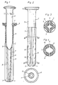
- Figure 1 is a side view of a device in accordance with the invention, including nail and plug, the latter in longitudinal section,
- Figure 2 are side and end views of the plug,
- Figure 3 is a cross section along the line III-III in Figure 2 and
- Figure 4 is a cross section along the line IV-IV in Figure 2.
- The device in accordance with the invention consists of a
plug 1 with a coacting nail or the like 2 adjusted to the length of the plug. The plug comprises anexpandable portion 3 provided with adiametral slit 8, theportion 3 extending from theinner end 4 of the plug and to anunexpandable portion 5, which may have different lengths depending on the field of use of the plug. At the outer end of the plug theportion 5 merges into acollar 6 in which there is the mouth of ahole 7 suited to the nail, and this hole tapers towards theinner end 4 of the plug in theexpandable portion 3, which is provided with four internal,longitudinal ridges 9. Corresponding to theseridges 9 there are fourgrooves 10 arranged in the cylindrical outer surface of the expandable portion. - The increase in the cross-sectional area of the expandable portion, which occurs in a direction towards the
inner end 4 of the plug, as a result of the taper of thehole 7, is compensated by the grooves at theinner end 4 of the plug having greater width and depth, which is illustrated by Figures 3 and 4, showing two different cross- sections of theexpandable portion 3. - By keeping the cross-sectional area constant, and, together with the nail area, in correspondence with the hole area, i.e. with the
filling factor 1, the material in the expandable portion of the plug will be redistributed and will assume an annular appearance when the plug is placed in a hole and the nail is driven in. There is thus achieved a large contact surface against the hole wall as well as high pressure on the contact surface, and thereby maximum reistance to withdrawal. - The forces in withdrawal stresses will be taken up by the head of the nail. In order to transmit larger forces between the expanded portion of the plug and the nail, the latter can be provided with a shallow, claw-like rolled thread over the portion coacting with the expandable portion of the plug. Screwing the nail out and removing the plug is thus enabled. The thread is formed such that it does not retard drivinq in the nail.
Claims (1)
- Fixing element for knocking into a pre-drilled hole in concrete or the like material in so-called straight-through fixing for fastening wall panels, studs etc., said fixing element consisting of a plug (1) with a nail (2) or the like expansion means coacting therewith, said plug preferably being manufactured in a rigid plastic material and including an expandable portion (3) extending from the inner end (4) of the plug in a fixed condition and preferably provide with a diametral slit (8), said portion (3) merging into a non- expandable zone (5) terminating at the outer end of the plug in a collar (6), the plug being formed with a central hole (7) starting from the end provided with the collar (6), the hole being adapted to the nail (2) and preferably tapering conically towards the inner end of the plug (4) in the expandable portion (3), in which it is provided with four internal longitudinal ridges (9), characterized in that the exterior surface of the expandable portion is provided with a plurality of longitudinal grooves (10) which together with the ridges (9) are formed such that the expandable portion has a substantially constant cross-sectional area along the greater portion of its length, the sum of the cross-sectional areas of the expandable portion (3) and the steel nail (2) being substantially equal to or fall to a minor extent below the cross-sectional area of a pre-drilled hole of nominal diameter.
Priority Applications (1)
| Application Number | Priority Date | Filing Date | Title |
|---|---|---|---|
| AT84900651T ATE39976T1 (en) | 1983-01-27 | 1984-01-25 | FASTENER FOR DRIVING INTO DRILLED HOLE. |
Applications Claiming Priority (2)
| Application Number | Priority Date | Filing Date | Title |
|---|---|---|---|
| SE8300423 | 1983-01-27 | ||
| SE8300423A SE434179B (en) | 1983-01-27 | 1983-01-27 | FIXING DEVICE FOR WRAPPING IN A PREVENTED HALL |
Publications (3)
| Publication Number | Publication Date |
|---|---|
| EP0134231A1 EP0134231A1 (en) | 1985-03-20 |
| EP0134231B1 true EP0134231B1 (en) | 1989-01-11 |
| EP0134231B2 EP0134231B2 (en) | 1993-05-26 |
Family
ID=20349788
Family Applications (1)
| Application Number | Title | Priority Date | Filing Date |
|---|---|---|---|
| EP19840900651 Expired - Lifetime EP0134231B2 (en) | 1983-01-27 | 1984-01-25 | Fixing element for knocking into a drilled hole |
Country Status (7)
| Country | Link |
|---|---|
| EP (1) | EP0134231B2 (en) |
| JP (1) | JPS60500224A (en) |
| DE (1) | DE3476103D1 (en) |
| DK (1) | DK153857C (en) |
| FI (1) | FI77514C (en) |
| SE (1) | SE434179B (en) |
| WO (1) | WO1984002961A1 (en) |
Families Citing this family (5)
| Publication number | Priority date | Publication date | Assignee | Title |
|---|---|---|---|---|
| FR2640657B1 (en) * | 1988-12-21 | 1993-05-21 | Itw De France | OBJECT INTENDED TO BE FIXED ON A THICK WALL, FOR EXAMPLE IN MASONRY |
| GB9012519D0 (en) * | 1990-06-05 | 1990-07-25 | Strachan & Henshaw Ltd | Connecting bolts |
| DE9307036U1 (en) * | 1993-05-08 | 1993-08-19 | Franke Gmbh & Co Kg | Fitting part that can be attached to a furniture component made of wood or a wood-like material |
| US5575600A (en) * | 1995-07-10 | 1996-11-19 | Anthony C. Giannuzzi | All-metal expansible anchor and nail assembly |
| CN106763049B (en) * | 2016-12-31 | 2019-03-05 | 中国工程物理研究院激光聚变研究中心 | Push away swollen drawing type flexible fastening connector |
Family Cites Families (5)
| Publication number | Priority date | Publication date | Assignee | Title |
|---|---|---|---|---|
| US1499071A (en) * | 1923-03-28 | 1924-06-24 | Henry B Newhall | Bolt anchor |
| DE889516C (en) * | 1951-08-01 | 1953-09-10 | Niedergesaess & Co | Expanding dowel |
| US3482482A (en) * | 1968-07-26 | 1969-12-09 | Usm Corp | Drive anchor fastening devices |
| US3613497A (en) * | 1969-04-10 | 1971-10-19 | U S Expansion Bolt Co | Expansion anchor |
| AU3281471A (en) * | 1970-08-27 | 1973-03-01 | Wa. Deutsher Proprietary Limited | Improved wall plug |
-
1983
- 1983-01-27 SE SE8300423A patent/SE434179B/en not_active IP Right Cessation
-
1984
- 1984-01-25 DE DE8484900651T patent/DE3476103D1/en not_active Expired
- 1984-01-25 JP JP50071784A patent/JPS60500224A/en active Granted
- 1984-01-25 WO PCT/SE1984/000023 patent/WO1984002961A1/en active IP Right Grant
- 1984-01-25 EP EP19840900651 patent/EP0134231B2/en not_active Expired - Lifetime
- 1984-09-11 FI FI843558A patent/FI77514C/en not_active IP Right Cessation
- 1984-09-26 DK DK460584A patent/DK153857C/en not_active IP Right Cessation
Also Published As
| Publication number | Publication date |
|---|---|
| FI77514C (en) | 1989-03-10 |
| JPH045844B2 (en) | 1992-02-03 |
| EP0134231A1 (en) | 1985-03-20 |
| EP0134231B2 (en) | 1993-05-26 |
| FI77514B (en) | 1988-11-30 |
| FI843558L (en) | 1984-09-11 |
| SE8300423D0 (en) | 1983-01-27 |
| DK460584A (en) | 1984-09-26 |
| DE3476103D1 (en) | 1989-02-16 |
| WO1984002961A1 (en) | 1984-08-02 |
| JPS60500224A (en) | 1985-02-21 |
| DK153857C (en) | 1989-04-10 |
| DK460584D0 (en) | 1984-09-26 |
| DK153857B (en) | 1988-09-12 |
| SE434179B (en) | 1984-07-09 |
| FI843558A0 (en) | 1984-09-11 |
Similar Documents
| Publication | Publication Date | Title |
|---|---|---|
| US4861206A (en) | Straddling plug | |
| US3942407A (en) | Expandable screw anchoring devices | |
| US5263803A (en) | Anchor bolt | |
| US5531553A (en) | Masonry fixing | |
| US3911781A (en) | Anchor sleeve for use in bores formed in relatively easily friable materials | |
| CA1141999A (en) | Expanding anchor bolt assembly | |
| US4481702A (en) | Method of assembling threaded insert bushing within a working material | |
| US5205688A (en) | Deformable plug of a wall fastener | |
| US4963062A (en) | Single-piece, pre-shaped anchor | |
| EP0401182B1 (en) | Anchoring bolt | |
| US4330230A (en) | Anchor bolt assembly | |
| US20010022924A1 (en) | Dowel | |
| US2470924A (en) | Fastening device | |
| US4195547A (en) | Anchor bolt assembly | |
| US3742809A (en) | Expansion anchor with conically tapered and threaded interacting parts | |
| JPH01150008A (en) | Expansion plug fixed into undercut drilled hole | |
| EP0134231B1 (en) | Fixing element for knocking into a drilled hole | |
| US4135432A (en) | Anchor for undercut bore | |
| US3217583A (en) | Unitary expansion anchor for bolts | |
| US4537541A (en) | Anchor bolt assembly | |
| EP0560789B1 (en) | Improved fixing | |
| US2984279A (en) | Locking insert with deformable flange bearing peripheral biting teeth | |
| JPH03107605A (en) | Expansion plug | |
| US3837257A (en) | Anchoring device | |
| US20060193711A1 (en) | Threaded bolt fastener |
Legal Events
| Date | Code | Title | Description |
|---|---|---|---|
| PUAI | Public reference made under article 153(3) epc to a published international application that has entered the european phase |
Free format text: ORIGINAL CODE: 0009012 |
|
| 17P | Request for examination filed |
Effective date: 19840825 |
|
| AK | Designated contracting states |
Designated state(s): AT BE CH DE FR GB LI NL |
|
| 17Q | First examination report despatched |
Effective date: 19860320 |
|
| GRAA | (expected) grant |
Free format text: ORIGINAL CODE: 0009210 |
|
| AK | Designated contracting states |
Kind code of ref document: B1 Designated state(s): AT BE CH DE FR GB LI NL |
|
| PG25 | Lapsed in a contracting state [announced via postgrant information from national office to epo] |
Ref country code: LI Effective date: 19890111 Ref country code: CH Effective date: 19890111 |
|
| REF | Corresponds to: |
Ref document number: 39976 Country of ref document: AT Date of ref document: 19890115 Kind code of ref document: T |
|
| REF | Corresponds to: |
Ref document number: 3476103 Country of ref document: DE Date of ref document: 19890216 |
|
| REG | Reference to a national code |
Ref country code: CH Ref legal event code: PL |
|
| ET | Fr: translation filed | ||
| PLBI | Opposition filed |
Free format text: ORIGINAL CODE: 0009260 |
|
| 26 | Opposition filed |
Opponent name: J.H. DE WIT EN ZONEN B.V. Effective date: 19891006 |
|
| NLR1 | Nl: opposition has been filed with the epo |
Opponent name: J.H. DE WIT EN ZONEN B.V. |
|
| PUAH | Patent maintained in amended form |
Free format text: ORIGINAL CODE: 0009272 |
|
| STAA | Information on the status of an ep patent application or granted ep patent |
Free format text: STATUS: PATENT MAINTAINED AS AMENDED |
|
| REG | Reference to a national code |
Ref country code: GB Ref legal event code: 732E |
|
| 27A | Patent maintained in amended form |
Effective date: 19930526 |
|
| AK | Designated contracting states |
Kind code of ref document: B2 Designated state(s): AT BE CH DE FR GB LI NL |
|
| REG | Reference to a national code |
Ref country code: FR Ref legal event code: TP |
|
| NLR2 | Nl: decision of opposition | ||
| ET3 | Fr: translation filed ** decision concerning opposition | ||
| NLR3 | Nl: receipt of modified translations in the netherlands language after an opposition procedure | ||
| NLS | Nl: assignments of ep-patents |
Owner name: THORSMAN & CO. AB TE NYKOEPING, ZWEDEN. |
|
| PGFP | Annual fee paid to national office [announced via postgrant information from national office to epo] |
Ref country code: FR Payment date: 19970109 Year of fee payment: 14 |
|
| PGFP | Annual fee paid to national office [announced via postgrant information from national office to epo] |
Ref country code: AT Payment date: 19970114 Year of fee payment: 14 |
|
| PGFP | Annual fee paid to national office [announced via postgrant information from national office to epo] |
Ref country code: GB Payment date: 19970116 Year of fee payment: 14 |
|
| PGFP | Annual fee paid to national office [announced via postgrant information from national office to epo] |
Ref country code: NL Payment date: 19970130 Year of fee payment: 14 |
|
| PGFP | Annual fee paid to national office [announced via postgrant information from national office to epo] |
Ref country code: DE Payment date: 19970131 Year of fee payment: 14 |
|
| PGFP | Annual fee paid to national office [announced via postgrant information from national office to epo] |
Ref country code: BE Payment date: 19970318 Year of fee payment: 14 |
|
| PG25 | Lapsed in a contracting state [announced via postgrant information from national office to epo] |
Ref country code: GB Free format text: LAPSE BECAUSE OF NON-PAYMENT OF DUE FEES Effective date: 19980125 Ref country code: AT Free format text: LAPSE BECAUSE OF NON-PAYMENT OF DUE FEES Effective date: 19980125 |
|
| PG25 | Lapsed in a contracting state [announced via postgrant information from national office to epo] |
Ref country code: BE Free format text: LAPSE BECAUSE OF NON-PAYMENT OF DUE FEES Effective date: 19980131 |
|
| BERE | Be: lapsed |
Owner name: THORSMAN & CO A.B. Effective date: 19980131 |
|
| PG25 | Lapsed in a contracting state [announced via postgrant information from national office to epo] |
Ref country code: NL Free format text: LAPSE BECAUSE OF NON-PAYMENT OF DUE FEES Effective date: 19980801 |
|
| GBPC | Gb: european patent ceased through non-payment of renewal fee |
Effective date: 19980125 |
|
| PG25 | Lapsed in a contracting state [announced via postgrant information from national office to epo] |
Ref country code: FR Free format text: THE PATENT HAS BEEN ANNULLED BY A DECISION OF A NATIONAL AUTHORITY Effective date: 19980930 |
|
| NLV4 | Nl: lapsed or anulled due to non-payment of the annual fee |
Effective date: 19980801 |
|
| PG25 | Lapsed in a contracting state [announced via postgrant information from national office to epo] |
Ref country code: DE Free format text: LAPSE BECAUSE OF NON-PAYMENT OF DUE FEES Effective date: 19981001 |
|
| REG | Reference to a national code |
Ref country code: FR Ref legal event code: ST |
|
| APAH | Appeal reference modified |
Free format text: ORIGINAL CODE: EPIDOSCREFNO |