EP0133923B1 - Alarm device for doors and windows - Google Patents
Alarm device for doors and windows Download PDFInfo
- Publication number
- EP0133923B1 EP0133923B1 EP84107829A EP84107829A EP0133923B1 EP 0133923 B1 EP0133923 B1 EP 0133923B1 EP 84107829 A EP84107829 A EP 84107829A EP 84107829 A EP84107829 A EP 84107829A EP 0133923 B1 EP0133923 B1 EP 0133923B1
- Authority
- EP
- European Patent Office
- Prior art keywords
- door
- contact
- window
- alarm device
- screws
- Prior art date
- Legal status (The legal status is an assumption and is not a legal conclusion. Google has not performed a legal analysis and makes no representation as to the accuracy of the status listed.)
- Expired
Links
Images

Classifications
-
- G—PHYSICS
- G08—SIGNALLING
- G08B—SIGNALLING OR CALLING SYSTEMS; ORDER TELEGRAPHS; ALARM SYSTEMS
- G08B13/00—Burglar, theft or intruder alarms
- G08B13/02—Mechanical actuation
- G08B13/08—Mechanical actuation by opening, e.g. of door, of window, of drawer, of shutter, of curtain, of blind
Definitions
- the invention relates to an alarm device according to the preamble of claim 1.
- Such an alarm device is known from GB-A-1 445 705.
- a microswitch is provided in the cavity behind the striking plate of a door lock, which is connected to a circuit together with another destructible electrical conductor.
- the microswitch is actuated by the door latch when the door is shut off, so that this circuit is closed.
- a resilient tongue arranged outside the microswitch is pushed through the bolt onto a spring pressure bolt of the microswitch.
- the resilient tongue protrudes into the opening into which the bolt is pushed when the door is locked.
- essential functional elements which are required to actuate the microswitch, are exposed and thus, for. B. by foaming, can be disabled.
- the microswitch also takes up a relatively large amount of space.
- the contact switch has a current-conducting switch housing housed in a metal housing provided with a screw-on plate.
- a switching plunger made of non-conductive material, in particular plastic, is slidably mounted.
- the switching plunger carries a current-conducting contact plate at its end opposite the striking plate side surface, which closes the current contact to the signaling device when the striking plate is lifted or bent off the frame wood.
- the contact switch which consists of a relatively large number of individual components, is of relatively complex construction. The distance between the contacts must be quite large, otherwise there is a risk that an alarm signal will be triggered even with relatively low vibrations.
- the known device should only respond when the window or door is opened by force.
- the object of the invention is therefore to provide an alarm device of the type mentioned, which has an extremely simple and space-saving structure and whose essential parts are protected against inoperative networks.
- the installation of the contact switch in the door or window frame is extremely simple and can also be done by a handyman.
- the installation can be adjusted to any window or door.
- the base plate, on which the two fixed contacts and the spring contact are provided can be attached in a height-adjustable manner relative to the bottom of the depression in which the contact switch is arranged. This can be done, for example, with the help of screws rotatable in the base plate, e.g. B. mirror screws happen, the underlying thread are designed in the manner of wood screw threads and can be screwed into the material of the door or window frame.
- Material changes for example the "working of the wood of the door or window frame that occurs over time, can also be compensated for in this way. It is achieved in this way that the base plate can be arranged as close as possible to the cover plate, which can be designed as a striking plate.
- the contact switch can be arranged as a latch lock or as a latch lock in the latch or latch opening of the door or window frame. It is of course also possible to provide the recess in which the contact switch is arranged at another point on the door or window frame.
- the spring contact is actuated by the latch or bolt or by a striking plate or an actuating element provided on the window or door leaf, so that the circuit is connected. As long as the circuit is switched on, the switched-on signal device is not actuated. However, if the circuit is opened by removing the spring contact from one of the two fixed contacts, the switched-on signaling device is activated.
- the signal device can be designed in a known manner and can, for example, deliver an acoustic or optical signal.
- the circuit is interrupted whenever the actuator by which the spring contact is brought into such a position that it connects the two fixed contacts to one another is removed from the spring contact. If the signaling device is switched on, the latter is then activated.
- the alarm device is insensitive to vibrations, which are generated, for example, by passing heavy vehicles or strong gusts of wind. Furthermore, the system responds not only when the door or window is opened by force, but also when it is opened carefully, which is not desired.
- the contact arrangement is designed so that the freely movable end of the leaf spring is movable between two fixed contacts for contacting them, it is possible to close two different circuits.
- One circuit can then be used for the alarm device and the other circuit can be used for other purposes. In this way, one obtains, without requiring additional space, a variety of possible uses for the alarm device, for example for monitoring the frequency of the door movements or closing and opening operations on the door for statistical purposes or security purposes or the triggering of automatic monitoring systems by the additional circuit and the like.
- a suitable carrier for this can be a plastic block which has a cavity in which the contacts are arranged accordingly.
- a projection made of electrically non-conductive material which protrudes through an opening in the plastic block and which is displaced when the door or window is closed and opened.
- the plastic block can be guided by means of screws on a holding frame, through which a displacement of the plastic block and thus the distance of the leaf spring relative to the actuating element, which acts on the latter when it is closed and opened, is achieved. In this way it can be achieved that the movable end of the leaf spring rests with security when the door or window is closed against the corresponding fixed contact for closing the closed circuit.
- a contact switch 3 is installed in a recess 9 of a door or window frame 7.
- the contact switch has a base plate 8 made of a non-conductive or insulating material as a support for the two fixed contacts 1 and 2.
- the two contacts 2 and 2 are passed through the base plate 8 and connected to connecting lines 15 and 16 on the rear side of the base plate. which lead to an actuating device 6 for a signal device 5 connected to the actuating device 6.
- a spring contact 4 designed as a leaf spring is electrically conductively and firmly connected.
- the other end of the spring contact 4 is freely movable and can be brought into conductive connection or contact with the other fixed contact 2.
- an actuator 12 which can be designed as a bolt or latch of the closing device of the door or window.
- the actuator can also be a projection provided on the window or door frame, which presses the spring contact 4 with its free end against the fixed contact 2 when the door or window is closed.
- a cover plate 10 can be provided which has an elongated opening 11 through which the actuating member 12 can be brought into effect on the spring contact 4.
- the spring contact 4 When the spring contact 4 is lifted off the fixed contact 2 at one end, as shown in FIG. 2, the spring contact 4 projects into the opening 11 of the cover plate 10.
- the cover plate 10 is attached to the door by means of screws 17 and 18 or window frame 7 attached. The surface of the cover plate 10 is flush with the surface of the door or window frame 7 surrounding it.
- the base plate 8 can be adjusted relative to the bottom 19 of the recess 9. This is done with the aid of screws 20 and 21, the thread of which is inserted in sleeves 22 and 23, which are anchored in the material of the door or window frame, for example screwed in.
- the sleeves 22 and 23 have internal threads into which the thread of the screws 20 and 21 is screwed.
- This height adjustment ensures that the spring contact 14 is always in the correct position, so that it is pressed into the closed position of the window or door by the actuator 12 with its free end on the fixed contact 2 or is brought into conductive connection .
- the closed circuit is interrupted, whereby the switched-on signal device 5 is put into operation. An acoustic or optical signal can then be emitted by the signal device 5.
- the actuating device 6 can be designed as a relay that actuates a switch that is open as long as the closed circuit is closed. When the closed circuit is interrupted, this switch is closed, as a result of which the signaling device 5 is activated.
- the actuating device 6 it is also possible to design the actuating device 6 as an electronic component, for example as a logic circuit (AND circuit, AND / OR circuit, etc.).
- the spring contact 4 preferably has an insulating layer 13, for example made of plastic, at the point at which it comes into contact with the actuating member 12.
- This insulating layer is advantageous if the actuator 12 consists of an electrically conductive material.
- the conductive part of the spring contact 4 is then electrically insulated from the actuator 12 by the isoller layer 13.
- the ball 14 is made of non-conductive material. In this way, possible changes in resistance and capacity of the alarm system are avoided, in particular when highly sensitive electronic control devices are used for the actuating device 6 and the signal device 5.
- the screw is rotatably mounted with its head part 25 in the base plate 8, so that a height adjustment of the base plate 8 relative to the bottom 19 of the recess in which the contact switch 3 is mounted is achieved.
- the carrier for the contacts is designed as a plastic block 27 which has a cavity 28, on the walls of which the contacts 1, 2 and a contact 26 are present.
- the contacts 1 and 2 correspond to the contacts 1 and 2 in the previous embodiments, i. H. the contacts 1 and 2 are connected to the circuit 6, 15, 16 shown in FIG. 1, for example, while the contacts 1 and 26 are connected to an additional circuit through which, for example, a counting device, a monitoring device or a triggering device for a monitoring device or an additional alarm circuit, which ensures an additional alarm triggering and the like. More can be connected.
- the free end of the leaf spring 4 has a projection 29 which projects through an opening 44 in the plastic block 27.
- the projection 29 projects beyond the front of the plastic block 27 by a small amount, which corresponds at least to the distance between the two contacts 2 and 26.
- the leaf spring 4 is practically completely covered to the outside, specifically by the front block side 45.
- Unnoticed opening of the door or window is not possible because the projection 29 together with the free end of the leaf spring 4 under the spring action of the opening movement of the actuator 12 in the open, non-foamed space in which the actuator 12 was previously has, would follow. This means that the breakdown of the essential components of the contact switch is avoided.
- the leaf spring 4 rests with its front surface in an electrically conductive connection on the fixed contact 26 which is on the front wall of the cavity 28 in the immediate vicinity above the through hole 44 for the Projection 29 is arranged.
- the front ends with which the screws 30 and 31 are inserted into the screw sleeves 35 and 36 are conical in order to make assembly easier.
- the screws 30 and 31 are, as can be seen from FIG. 7 for the upper screw, their thickened rear ends (in FIG. 7 hemispherical end 46) in slots 37, 38 in the rear wall of the holding frame 32 by means of anchored in the screw in front of the reinforced end circumferential groove 49. It is also possible to support the back of the thickened end of the screw against a stop surface which is formed, for example, by a U-shaped part.
- the screws 30 and 31 without tilting into the cast-in screw sleeves 35 and 36 with the aid of a suitable tool inserted between the plastic block 27 and the side walls of the holding frame 32 with the preferably conical ends of the screws 30 and 31 .
- a suitable tool inserted between the plastic block 27 and the side walls of the holding frame 32 with the preferably conical ends of the screws 30 and 31 .
- the thickened ends of the screws 30 and 31 lie, as can be seen from FIG. 7, on the rear outside of the rear wall of the holding frame 32 and form an abutment during the assembly of the plastic block 27.
- the plastic block 27 sits on the Bottom part 47 of the holding frame 32.
- the holding frame 32 is preferably made of sheet metal, and the shaping is achieved by stamping and folding.
- suitable spacers can be provided on the outside of the rear wall of the holding frame 32 or the distance can be set similar to that in FIGS Figures 2 to 4 is shown with the aid of screws 20, 21, which are inserted in the material of the ster- or door frame anchored sleeves 22, 23, wherein the screws 20, 21 can be designed as M-threaded screws.
- the screws 30, 31, as shown for the case of the screw 30 in Fig. 7, near it Thickened ends have a square screw part 39.
- This screw part 39 can also be polygonal.
- the lateral surfaces of this screw part 39 are alternately electrically conductive and electrically insulating.
- An electrically conductive leaf spring 40 bears against this polygonal screw part 39, which is fastened to the rear wall of the holding frame 32 with the aid of a non-conductive holder 48.
- the leaf springs 40 and the polygonal screw part 39 are connected in sabotage circuits, not shown, through which an alarm can be triggered if the screws 30 and 31 are inadvertently turned.
- This alarm is triggered if, when the screws 30 and 31 are turned, there is a change from one side face to the next following side face, i. H. when the leaf springs 40 abut against a conductive surface when the screws are turned against an electrically non-conductive surface, as a result of which the current in the sabotage circuits is then interrupted and an activated alarm device is activated.
- a current is switched into the corresponding circuit, which in turn then sets an alarm device into operation.
- FIG. 6 there is a conductive film 42 in a side wall 41 of the holding frame 32, which is connected to a further electrical sabotage circuit, not shown in detail.
- This conductive film 42 is insulated from the sheet metal of the holding frame 42, which forms the neutral conductor.
- it is also possible to isolate several of them Provided conductive foils 42 in the side wall 41 of the holding frame 32, which are connected in a circuit, not shown. If the holding frame is drilled laterally with the aid of a metal tool, for example a drill, the conductive foils 42 are short-circuited to one another or to the sheet metal holding frame, so that an alarm device can be triggered. In this respect, a lateral protection of the contact switch against lateral drilling and e.g. subsequent foaming is achieved.
Landscapes
- Physics & Mathematics (AREA)
- General Physics & Mathematics (AREA)
- Burglar Alarm Systems (AREA)
- Push-Button Switches (AREA)
Abstract
Description
Die Erfindung betrifft eine Alarmvorrichtung nach dem Oberbegriff des Anspruchs 1.The invention relates to an alarm device according to the preamble of
Eine derartige Alarmvorrichtung ist aus der GB-A-1 445 705 bekannt. Bei dieser bekannten Alarmvorrichtung ist in der Höhlung hinter dem Schließblech eines Türschlosses ein Mikroschalter vorgesehen, der zusammen mit einem weiteren zerstörbaren elektrischen Leiter in einen Stromkreis geschaltet ist. Durch den Türriegel wird beim Absperren der Tür der Mikroschalter betätigt, so daß dieser Stromkreis geschlossen ist. Hierzu wird eine außerhalb des Mikroschalters angeordnete federnde Zunge durch den Riegel auf einen Federdruckbolzen des Mikroschalters aufgeschoben. Die federnde Zunge ragt in die Öffnung, in die der Riegel beim Absperren der Tür geschoben wird. Das bedeutet, daß wesentliche Funktionselemente, welche zur Betätigung des Mikroschalters erforderlich sind, freiliegen und damit, z. B. durch Ausschäumen, außer Funktion gesetzt werden können. Zudem hat auch der Mikroschalter einen relativ großen Platzbedarf.Such an alarm device is known from GB-A-1 445 705. In this known alarm device, a microswitch is provided in the cavity behind the striking plate of a door lock, which is connected to a circuit together with another destructible electrical conductor. The microswitch is actuated by the door latch when the door is shut off, so that this circuit is closed. For this purpose, a resilient tongue arranged outside the microswitch is pushed through the bolt onto a spring pressure bolt of the microswitch. The resilient tongue protrudes into the opening into which the bolt is pushed when the door is locked. This means that essential functional elements, which are required to actuate the microswitch, are exposed and thus, for. B. by foaming, can be disabled. The microswitch also takes up a relatively large amount of space.
Bei einer weiteren aus der DE-B-1 283 124 bekannten Alarmvorrichtung besitzt der Kontaktschalter ein in einem mit einer Anschraubplatte versehenen Metallgehäuse untergebrachtes stromleitendes Schaltergehäuse. In diesem ist ein aus nichtleitendem Werkstoff, insbesondere Kunststoff, bestehender Schaltstößel verschiebbar gelagert. Der Schaltstößel trägt an seinem der Schließblechseitenfläche gegenüberliegenden Ende eine stromleitende Kontaktplatte, die beim Abheben oder Abbiegen des Schließblechs vom Rahmenholz den Stromkontakt zur Signaleinrichtung schließt. Dabei wird bei geschlossener Tür der Schaltstößel mit Hilfe einer zusätzlich vorgesehenen Druckfeder gegen die Schließblechseitenfläche gedrückt. Bei dieser Alarmvorrichtung ist der Kontaktschalter, welcher aus relativ vielen Einzeibestandteilen besteht, relativ aufwendig aufgebaut. Der Abstand der Kontakte voneinander muß ziemlich groß bemessen sein, weil sonst die Gefahr besteht, daß schon bei relativ geringen Erschütterungen ein Alarmsignal ausgelöst wird. Außerdem soll die bekannte Vorrichtung nur bei gewaltsamem Öffnen des Fensters oder der Tür ansprechen.In another alarm device known from DE-B-1 283 124, the contact switch has a current-conducting switch housing housed in a metal housing provided with a screw-on plate. In this a switching plunger made of non-conductive material, in particular plastic, is slidably mounted. The switching plunger carries a current-conducting contact plate at its end opposite the striking plate side surface, which closes the current contact to the signaling device when the striking plate is lifted or bent off the frame wood. When the door is closed, the switching plunger is pressed against the striking plate side surface with the help of an additional compression spring. In this alarm device, the contact switch, which consists of a relatively large number of individual components, is of relatively complex construction. The distance between the contacts must be quite large, otherwise there is a risk that an alarm signal will be triggered even with relatively low vibrations. In addition, the known device should only respond when the window or door is opened by force.
Dies trifft auch für andere Kontaktschalter in bekannten Alarmvorrichtungen zu DE-A-20 45 904, DE-A-24 38 817, DE-C-53 154, DE-C-375 699. DE-C-597 733 und US-A-26 60 632).This also applies to other contact switches in known alarm devices to DE-A-20 45 904, DE-A-24 38 817, DE-C-53 154, DE-C-375 699. DE-C-597 733 and US-A -26 60 632).
Aufgabe der Erfindung ist es daher, eine Alarmvorrichtung der eingangs genannten Art zu schaffen, die einen äußerst einfachen und raumsparenden Aufbau aufweist und deren funktionswesentlichen Teile gegen Außerfunktionsetzen geschützt sind.The object of the invention is therefore to provide an alarm device of the type mentioned, which has an extremely simple and space-saving structure and whose essential parts are protected against inoperative networks.
Diese Aufgabe wird erfindungsgemäß durch die kennzeichnenden Merkmale des Anspruchs 1 gelöst.This object is achieved by the characterizing features of
Die Unteransprüche enthalten Weiterbildungen der Erfindung.The subclaims contain developments of the invention.
Vorteilhaft ist bei der Erfindung nicht nur der einfache Aufbau, insbesondere des Kontaktschalters, sondern auch dessen verdeckte Anordnung. Die Installation des Kontaktschalters in den Tür- bzw. Fensterrahmen ist äußerst einfach und kann auch von einem Heimwerker ausgeführt werden. Der Einbau kann auf jedes Fenster oder jede Tür eingestellt werden. Insbesondere läßt sich die Grundplatte, an der die beiden feststehenden Kontakte und der Federkontakt vorgesehen sind, gegenüber dem Boden der Vertiefung, in welcher der Kontaktschalter angeordnet ist, höhenverstellbar befestigen. Dies kann beispielsweise mit Hilfe von in die Grundplatte drehbaren Schrauben, z. B. Spiegelschrauben, geschehen, deren dahinterliegendes Gewinde nach Art von Holzschraubengewinden ausgebildet sind und in das Material des Tür- bzw. Fensterrahmens eingeschraubt werden können. Auch Materialveränderungen, beispielsweise das mit der Zeit auftretende « Arbeiten des Holzes des Tür- bzw. Fensterrahmens kann auf diese Weise ausgeglichen werden. Es wird auf diese Weise erzielt, daß die Grundplatte möglichst nahe an der Abdeckplatte, welche als Schließblech ausgebildet sein kann, angeordnet werden kann.Not only the simple structure, in particular the contact switch, but also its concealed arrangement is advantageous in the invention. The installation of the contact switch in the door or window frame is extremely simple and can also be done by a handyman. The installation can be adjusted to any window or door. In particular, the base plate, on which the two fixed contacts and the spring contact are provided, can be attached in a height-adjustable manner relative to the bottom of the depression in which the contact switch is arranged. This can be done, for example, with the help of screws rotatable in the base plate, e.g. B. mirror screws happen, the underlying thread are designed in the manner of wood screw threads and can be screwed into the material of the door or window frame. Material changes, for example the "working of the wood of the door or window frame that occurs over time, can also be compensated for in this way. It is achieved in this way that the base plate can be arranged as close as possible to the cover plate, which can be designed as a striking plate.
Der Kontaktschalter kann als Fallensicherung oder als Riegelsicherung in der Riegel- oder Fallenöffnung des Tür- bzw. Fensterrahmens angeordnet sein. Es ist natürlich auch möglich, die Vertiefung, in welcher der Kontaktschalter angeordnet wird, auch an einer anderen Stelle des Tür- bzw. Fensterrahmens vorzusehen. Der Federkontakt wird von der Falle oder dem Riegel bzw. von einem Schließblech oder einem am Fenster- oder Türflügel vorgesehenen Betätigungselement betätigt, so daß der Stromkreis angeschlossen wird. Solange der Stromkreis eingeschaltet ist, wird die eingeschaltete Signaleinrichtung nicht betätigt. Wenn jedoch der Stromkreis durch Entfernen des Federkontaktes von einem der beiden feststehenden Kontakte geöffnet wird, wird die eingeschaltete Signaleinrichtung in Tätigkeit gesetzt. Die Signaleinrichtung kann in bekannter Weise ausgebildet sein und beispielsweise ein akustisches oder optisches Signal liefern.The contact switch can be arranged as a latch lock or as a latch lock in the latch or latch opening of the door or window frame. It is of course also possible to provide the recess in which the contact switch is arranged at another point on the door or window frame. The spring contact is actuated by the latch or bolt or by a striking plate or an actuating element provided on the window or door leaf, so that the circuit is connected. As long as the circuit is switched on, the switched-on signal device is not actuated. However, if the circuit is opened by removing the spring contact from one of the two fixed contacts, the switched-on signaling device is activated. The signal device can be designed in a known manner and can, for example, deliver an acoustic or optical signal.
Der Stromkreis wird immer dann unterbrochen, wenn das Betätigungsglied, durch welches der Federkontakt in eine solche Stellung gebracht wird, daß er beide feststehende Kontakte miteinander verbindet, vom Federkontakt entfernt wird. Wenn die Signaleinrichtung eingeschaltet ist, wird letztere dann in Tätigkeit gesetzt.The circuit is interrupted whenever the actuator by which the spring contact is brought into such a position that it connects the two fixed contacts to one another is removed from the spring contact. If the signaling device is switched on, the latter is then activated.
Die Alarmvorrichtung ist unempfindlich gegenüber Erschütterungen, welche beispielsweise durch vorbeifahrende schwere Fahrzeuge oder starke Windböen erzeugt werden. Ferner spricht die Anlage nicht nur bei gewaltsamem Öffnen der Tür bzw. des Fensters an, sondern auch bei vorsichtigem, nicht erwünschtem Öffnen.The alarm device is insensitive to vibrations, which are generated, for example, by passing heavy vehicles or strong gusts of wind. Furthermore, the system responds not only when the door or window is opened by force, but also when it is opened carefully, which is not desired.
Wenn die Kontaktanordnung so ausgebildet ist, daß das frei bewegliche Ende der Blattfeder zwischen zwei feststehenden Kontakten zur jeweiligen Kontaktgabe mit diesen beweglich ist, ist es möglich, zwei verschiedene Stromkreise zu schließen. Der eine Stromkreis kann dann für die Alarmvorrichtung verwendet werden und der andere Stromkreis läßt sich für andere Zwecke verwenden. Auf diese Weise erhält man, ohne daß zusätzlicher Platz benötigt wird, eine Vielfalt von Anwendungsmöglichkeiten für die Alarmvorrichtung, beispielsweise für die Überwachung der Frequenz der Türbewegungen bzw. Schließ- und Öffnungsvorgänge an der Tür für statistische Zwecke oder Sicherungszwecke oder das Auslösen automatischer Überwachungssysteme durch den zusätzlichen Stromkreis und dergleichen mehr.If the contact arrangement is designed so that the freely movable end of the leaf spring is movable between two fixed contacts for contacting them, it is possible to close two different circuits. One circuit can then be used for the alarm device and the other circuit can be used for other purposes. In this way, one obtains, without requiring additional space, a variety of possible uses for the alarm device, for example for monitoring the frequency of the door movements or closing and opening operations on the door for statistical purposes or security purposes or the triggering of automatic monitoring systems by the additional circuit and the like.
Ein geeigneter Träger hierfür kann ein Kunststoffblock sein, der einen Hohlraum aufweist, in welchem die Kontakte entsprechend angeordnet sind. Am freien Ende der Blattfeder befindet sich dann ein Vorsprung aus elektrisch nicht leitendem Material, der durch eine Öffnung im Kunststoffblock ragt und welcher beim Schließen und Öffnen der Tür bzw. des Fensters verschoben wird. Der Kunststoffblock kann hierzu mittels Schrauben an einem Halterahmen geführt sein, durch die auch eine Verschiebung des Kunststoffblockes und damit des Abstandes der Blattfeder gegenüber dem Betätigungsglied, welches beim Schließen und Öffnen auf diese einwirkt, erreicht wird. Hierdurch läßt sich erzielen, daß das bewegliche Ende der Blattfeder mit Sicherheit bei verschlossener Tür bzw. verschlossenem Fenster gegen den entsprechenden feststehenden Kontakt zur Schließung des Ruhestromkreises anliegt.A suitable carrier for this can be a plastic block which has a cavity in which the contacts are arranged accordingly. At the free end of the leaf spring there is a projection made of electrically non-conductive material, which protrudes through an opening in the plastic block and which is displaced when the door or window is closed and opened. For this purpose, the plastic block can be guided by means of screws on a holding frame, through which a displacement of the plastic block and thus the distance of the leaf spring relative to the actuating element, which acts on the latter when it is closed and opened, is achieved. In this way it can be achieved that the movable end of the leaf spring rests with security when the door or window is closed against the corresponding fixed contact for closing the closed circuit.
Anhand der beiliegenden Figuren wird an einem Ausführungsbeispiel die Erfindung noch näher erläutert. Es zeigt :
Figur 1 in schematischer Darstellung ein Ausführungsbeispiel, wobei die Anordnung des Kontaktschalters im Tür- bzw. Fensterrahmen und auseinandergezogener Darstellung gezeigt sind ;Figur 2 eine Seitenansicht des eingebauten Kontaktschalters mit noch abgehobener Abdeckplatte ;Figur 3 in Seitenansicht ein weiteres Ausführungsbeispiel ;- Figur 4 die Einzelheit A in Fig. 2 in - vergrößerter Darstellung ;
Figur 5 eine Ausführungsform in Form eines Kunststoffblockes für den Träger der Kontakte des Kontaktschalters in Seitenansicht;Figur 6 in perspektivischer Ansicht einen Halterahmen sowie den in der Fig. 5 dargestellten Kunststoffblock mit den Kontakten vor dem Zusammenbau und- Figur 7 in perspektivischer Ansicht eine Sicherung für die Halteschrauben, mit denen der als Kunststoffblock in den
Figuren 5 und 6 dargestellte Träger an der Rückseite des Halterahmens befestigt ist.
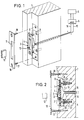
- Figure 1 shows a schematic representation of an embodiment, the arrangement of the contact switch in the door or window frame and exploded view are shown;
- Figure 2 is a side view of the built-in contact switch with the cover plate still raised;
- Figure 3 shows a side view of another embodiment;
- FIG. 4 shows detail A in FIG. 2 in an enlarged representation;
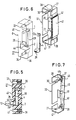
- Figure 5 shows an embodiment in the form of a plastic block for the carrier of the contacts of the contact switch in side view;
- 6 shows a perspective view of a holding frame and the plastic block shown in FIG. 5 with the contacts before assembly and
- Figure 7 is a perspective view of a fuse for the retaining screws with which the carrier shown as a plastic block in Figures 5 and 6 is attached to the back of the holding frame.
Beim dargestellten Ausführungsbeispiel der Figuren 1 und 2 ist ein Kontaktschalter 3 in einer Vertiefung 9 eines Tür- bzw. Fensterrahmens 7 eingebaut. Der Kontaktschalter besitzt eine aus einem nichtleitenden bzw. isolierenden Material bestehende Grundplatte 8 als Träger für die beiden feststehenden Kontakte 1 und 2. Die beiden Kontakte 2 und 2 sind durch die Grundplatte 8 hindurchgeführt und auf der Rückseite der Grundplatte mit Verbindungsleitungen 15 und 16 verbunden, die zu einer Betätigungseinrichtung 6 für eine an die Betätigungseinrichtung 6 angeschlossene Signaleinrichtung 5 führen.In the illustrated embodiment of Figures 1 and 2, a
Mit dem einen feststehenden Kontakt 1 an der Grundplatte 8 ist das eine Ende eines als Blattfeder ausgebildeten Federkontaktes 4 elektrisch leitend und fest verbunden. Das andere Ende des Federkontaktes 4 ist frei beweglich und kann mit dem anderen feststehenden Kontakt 2 in leitende Verbindung bzw. Berührung gebracht werden. Dies erfolgt durch ein Betätigungsglied 12, welches als Riegel oder Falle der Schließeinrichtung der Tür bzw. des Fensters ausgebildet sein kann. Das Betätigungsglied kann auch ein am Fenster- bzw. Türrahmen vorgesehener Vorsprung sein, der beim Schließen der Tür bzw. des Fensters den Federkontakt 4 mit seinem freien Ende gegen den feststehenden Kontakt 2 drückt.With the one fixed
Zum Schutz der Grundplatte 8 kann eine Abdeckplatte 10 vorgesehen sein, die eine längliche Öffnung 11 aufweist, durch welche das Betätigungsglied 12 auf den Federkontakt 4 zur Einwirkung gebracht werden kann. Wenn der Federkontakt 4 von dem feststehenden Kontakt 2 mit seinem einen Ende abgehoben ist, wie das in Fig.2 dargestellt ist, ragt der Federkontakt 4 in die Öffnung 11 der Abdeckplatte 10. Die Abdeckplatte 10 ist mit Hilfe von Schrauben 17 und 18 am Tür bzw. Fensterrahmen 7 befestigt. Die Oberfläche der Abdeckplatte 10 ist bündig mit der diese umgebenden Oberfläche des Tür- bzw. Fensterrahmens 7.To protect the
Innerhalb der Vertiefung 9 kann die Grundplatte 8 gegenüber dem Boden 19 der Vertiefung 9 verstellt werden. Dies geschieht mit Hilfe von Schrauben 20 und 21, deren Gewinde eingesetzt ist in Hülsen 22 und 23, die in Material des Tür- bzw. Fensterrahmens verankert sind, beispielsweise eingeschraubt sind. Die Hülsen 22 und 23 besitzen Innengewinde, in die das Gewinde der Schrauben 20 und 21 eingeschraubt wird.Within the
Je nachdem, wie tief die Schrauben 20 und 21 in die Hülsen 22 und 23 eingeschraubt werden, ergibt sich eine « Höheneinstellung » der Grundplatte 8 gegenüber dem Boden 19 der Vertiefung 9.Depending on how deep the
Durch diese Höheneinstellung wird gewährleistet, daß der Federkontakt 14 immer in der richtigen Lage ist, so daß dieser in Schließstellung des Fensters bzw. der Tür durch das Betätigungsglied 12 mit seinem freien Ende auf den feststehenden Kontakt 2 aufgedrückt wird bzw. in leitende Verbindung gebracht wird.This height adjustment ensures that the
Wenn der Federkontakt 4 die beiden feststehenden Kontakte 1 und 2 miteinander in elektrisch leitende Verbindung bringt, wird über die Betätigungseinrichtung 6 und die beiden Verbindungsleitungen 15 und 16 ein Ruhestromkreis gebildet. Wenn dieser Ruhestromkreis geschlossen ist, bleibt die eingeschaltete Signaleinrichtung 5 unbetätigt, d. h. es wird kein Alarmsignal ausgelöst.When the spring contact 4 brings the two fixed
Wird jedoch das Betätigungsglied 12 vom Federkontakt 4 entfernt, wird der Ruhestromkreis unterbrochen, wodurch die eingeschaltete Signaleinrichtung 5 in Betrieb gesetzt wird. Es kann dann ein akustisches oder optisches Signal von der Signalvorrichtung 5 abgegeben werden.However, if the
Die Betätigungseinrichtung 6 kann als Relais ausgebildet sein, das einen Schalter betätigt, der so lange geöffnet ist, wie der Ruhestromkreis geschlossen ist. Beim Unterbrechen des Ruhestromkreises wird dieser Schalter geschlossen, wodurch die Signaleinrichtung 5 in Tätigkeit versetzt wird. Es ist jedoch auch möglich, die Betätigungseinrichtung 6 als elektronischen Bauteil, beispielsweise als logische Schaltung (UND-Schaltung, UND/ODER-Schaltung usw.) auszubilden.The
Der Federkontakt 4 besitzt an der Stelle, an welcher er mit dem Betätigungsglied 12 in Berührung kommt, bevorzugt eine Isolierschicht 13, beispielsweise aus Kunststoff.The spring contact 4 preferably has an insulating
Diese Isolierschicht ist dann von Vorteil, wenn das Betätigungsglied 12 aus einem elektrisch leitfähigen Material besteht. Durch die Isollerschicht 13 wird dann der leitfähige Teil des Federkontaktes 4 vom Betätigungsglied 12 elektrisch isoliert.This insulating layer is advantageous if the
Bei dem in der Fig. 3 dargestellten Ausführungsbeispiel befindet sich zwischen dem Federkontakt 4 und dem Betätigungsglied 12 eine Kugel 14. Diese Kugel 14 ragt in eine konisch ausgebildete Öffnung 24 in der Grundplatte 8. Ein kalottenförmiger Teil der Kugel 14 ragt über die äußere Ebene der Grundplatte 8 hinaus und kann mit dem Betätigungsglied 12 in Berührung gebracht werden. Die Wirkungsweise dieser Anordnung ist die gleiche wie beim Ausführungsbeispiel der Figuren 1 und 2. In vorteilhafter Weise besteht die Kugel 14 aus nichtleitendem Material. Auf diese Weise werden mögliche Widerstands-und Kapazitätsänderungen des Alarmsystems vermieden, insbesondere dann, wenn hochsensitive elektronische Steuereinrichtungen für die Betätigungseinrichtung 6 und die Signaleinrichtung 5 verwendet werden.In the embodiment shown in FIG. 3 there is a
Wie aus der Fig. 4 zu ersehen ist, ist die Schraube mit ihrem Kopfteil 25 drehbar in der Grundplatte 8 gelagert, so daß eine Höhenverstellung der Grundplatte 8 gegenüber dem Boden 19 der Vertiefung, in welcher der Kontaktschalter 3 gelagert ist, erzielt wird.As can be seen from Fig. 4, the screw is rotatably mounted with its
Bei der in den Figuren 5 und 6 dargestellten Ausführungsform ist der Träger für die Kontakte als Kunststoffblock 27 ausgebildet, der einen Hohlraum 28 aufweist, an dessen Wände die Kontakte 1, 2 und ein Kontakt 26 vorhanden sind. Die Kontakte 1 und 2 entsprechen den Kontakten 1 und 2 in den vorherigen Ausführungsbeispielen, d. h. die Kontakte 1 und 2 sind an den beispielsweise in der Figur 1 dargestellten Schaltkreis 6, 15, 16 geschaltet, während die Kontakte 1 und 26 in einen zusätzlichen Schaltkreis geschaltet sind, durch den beispielsweise eine Zähleinrichtung, eine Überwachungseinrichtung oder eine Auslöseeinrichtung für eine Überwachungseinrichtung oder ein zusätzlicher Alarmstromkreis, der eine zusätzliche Alarmauslösung gewährleistet, und dgl. mehr angeschlossen sein können.In the embodiment shown in FIGS. 5 and 6, the carrier for the contacts is designed as a
Das freie Ende der Blattfeder 4 besitzt einen Vorsprung 29, der durch eine Öffnung 44 im Kunststoffblock 27 ragt. Der Vorsprung 29 steht um einen geringen Betrag, der mindestens dem Abstand zwischen den beiden Kontakten 2 und 26 entspricht, über die Vorderseite des Kunststoffblockes 27 über. Durch das Betätigungsglied 12, beispielsweise einen Riegel, kann beim Verschließen der Tür der Vorsprung 29 in der Fig. 5 nach rechts verschoben werden, bis die Blattfeder 4 mit ihrem unteren freien Ende in elektrischen Kontakt kommt mit dem Kontakt 2. Wenn das Betätigungsglied 12 nach links verschoben wird, bewegt sich unter der Federvorspannung die Blattfeder 4 ebenfalls nach links, bis die Blattfeder in elektrisch leitende Verbindung mit dem Kontakt 26 kommt, wie es in der Fig. 5 dargestellt ist. Hierdurch wird der im vorstehenden erwähnte zweite Stromkreis geschlossen.The free end of the leaf spring 4 has a
Auch bei diesem Ausführungsbeispiel ist die Blattfeder 4 nach außen hin praktisch vollständig abgedeckt, und zwar durch die vordere Blockseite 45. Die Außerbetriebsetzung der Blattfeder durch Ausschäumen des Hohlraums, welcher vor der vorderen Blockseite 45 vorhanden ist, mit Kunststoff, um ein unbemerktes Zurückziehen des Betätigungsgliedes- 12, d. h. ein unbemerktes Öffnen der Tür oder des Fensters durchzuführen, ist nicht möglich, weil der Vorsprung 29 zusammen mit dem freien Ende der Blattfeder 4 unter der Federwirkung der Öffnungsbewegung des Betätigungsgliedes 12 in den offenen, nicht ausgeschäumten Raum, in welchem sich das Betätigungsglied 12 vorher befunden hat, folgen würde. Das bedeutet, daß die Außerfunktionssetzung der wesentlichen Bestandteile des Kontaktschalters vermieden wird.In this embodiment, too, the leaf spring 4 is practically completely covered to the outside, specifically by the
Damit gewährleistet wird, daß in der Schließstellung des Betätigungsgliedes 12 die Blattfeder 4 mit Sicherheit mit ihrem frei beweglichen Ende in elektrischen Kontakt am Kontakt 2, der an der Rückwand des Hohlraumes 28 im Kunststoffblock 27 vorhanden ist, anliegt, ist nicht nur der Vorsprung 29 entsprechend lang bemessen, so daß er mindestens um die Bewegungsstrecke des unteren Endes der Blattfeder 4 über die Vorderseite des Kunststoffblockes übersteht, sondern es ist auch noch eine Einstellmöglichkeit durch die Schrauben 30, 31, wie im folgenden näher erläutert wird, vorhanden.This ensures that in the closed position of the
Um den Abstand der vordersten Spitze des Vorsprungs 29 gegenüber dem Betätigungsglied 12 so einzustellen, daß bei der Bewegung des Betätigungsgliedes 12 durch dieses auch das unter Ende der Blattfeder 4 in elektrischen Kontakt mit dem feststehenden Kontakt 2 gebracht wird, sind in Bohrungen 33, 34 des Kunststoffblockes 27 Innengewinde, beispielsweise in Form von eingegossenen Schraubhülsen 35, 36 vorgesehen. In die Innengewinde dieser Schraubhülsen 35 und 36 sind die Schrauben 30, 31 eingesetzt. Anstelle der eingegossenen Schraubhülsen 35 können auch Spreizdübel in die Bohrungen 33 und 34 eingesetzt werden, in die die Schrauben 30, 31 eingesetzt sind. Durch die vorderen Öffnungen der Bohrungen 33 und 34 läßt sich ein Werkzeug, z. B. ein Schraubenzieher, hindurchstecken und in den jeweiligen Schraubschlitz am konisch geformten Schraubenkopf einsetzen und die Schraube verdrehen, wodurch nicht nur eine Befestigung des Kunststoffblockes 27 am in der Figur 6 im einzelnen dargestellten Halterahmen 32 erzielt wird, sondern auch eine genaue Einstellung des Abstandes des Isolierblockes 27 und damit des Abstandes der Blattfeder 4 bzw. der vorderen Spitze des Vorsprunges 29 vom Betätigungsglied 12, das in Richtung auf die Blattfeder 4 zu bzw. in Richtung auf den Vorsprung 29 zu und von diesem weg beweglich ist. Damit wird gewährleistet, daß durch den zur Verfügung stehenden Verschiebeweg des Betätigungsgliedes 12 bei der Schließstellung des Betätigungsgliedes 12 das frei bewegliche Ende der Blattfeder 4 in Anlage kommt mit dem festen Kontakt 2.In order to adjust the distance of the foremost tip of the
Wenn das Betätigungsglied 12 in die geöffnete Stellung zurückgebracht wird, liegt, wie schon erwähnt, die Blattfeder 4 mit ihrer vorderen Fläche in elektrisch leitender Verbindung am festen Kontakt 26 an, der an der Vorderwand des Hohlraumes 28 in unmittelbarer Nähe über der Durchgangsbohrung 44 für den Vorsprung 29 angeordnet ist.When the
Wie schon erwähnt, sind die vorderen Enden, mit denen die Schrauben 30 und 31 in die Schraubhülsen 35 und 36 eingesetzt sind, konisch ausgebildet zwecks Montageerleichterung. Bei der Montage werden die Schrauben 30 und 31 mit, wie aus der Fig. 7 für die obere Schraube erkennbar ist, ihren verdickt ausgebildeten rückwärtigen Enden (in Fig. 7 halbkugelförmiges Ende 46) in Schlitzen 37, 38 in der Rückwand des Halterahmens 32 mittels einer vor dem verstärkten Ende in die Schraube eingeformten umlaufenden Nut 49 verankert. Es ist auch möglich, die Rückseite des verdickt ausgebildeten Endes der Schraube gegen eine Anschlagfläche abzustützen, die gebildet wird beispielsweise von einem U-förmigen Teil. Auf diese Weise ist es möglich, die Schrauben 30 und 31 verkantungsfrei mit Hilfe eines geeigneten, zwischen den Kunststoffblock 27 und den Seitenwänden des Halterahmens 32 eingesteckten Werkzeugs mit den bevorzugt ausgebildeten konisch zulaufenden Enden der Schrauben 30 und 31 in die eingegossenen Schraubhülsen 35 und 36 einzusetzen. Natürlich ist es auch möglich, die eine Schraube, insbesondere die obere Schraube 30, länger auszubilden als die andere oder eine Schablone als Montagehilfe zu verwenden. Die verdickt ausgebildeten Enden der Schrauben 30 und 31 liegen dabei, wie aus der Fig. 7 zu ersehen ist, an der rückwärtigen Außenseite der Rückwand des Halterahmens 32 an und bilden ein Widerlager bei der Montage des Kunststoffblocks 27. Der Kunststoffblock 27 sitzt dabei auf dem Bodenteil 47 des Halterahmens 32 auf. Der Halterahmen 32 besteht bevorzugterweise aus Blech, und die Formgebung wird durch Stanzen und Abkanten erreicht.As already mentioned, the front ends with which the
Um den für die verdickt ausgebildeten Enden an der Außenseite der Rückwand benötigten Abstand von dem Material des Tür- bzw. Fensterrahmens zu erhalten, können geeignete Abstandhalter an der Außenseite der Rückwand des Halterahmens 32 vorgesehen sein oder der Abstand kann eingestellt sein ähnlich wie es in den Figuren 2 bis 4 dargestellt ist mit Hilfe von Schrauben 20, 21, die in dem Material des ster- bzw. Türrahmens verankerten Hülsen 22, 23 eingesetzt sind, wobei die Schrauben 20, 21 als M-Gewindeschrauben ausgebildet sein können.In order to obtain the required distance from the material of the door or window frame for the thickened ends on the outside of the rear wall, suitable spacers can be provided on the outside of the rear wall of the holding
Zur Sicherung der Schrauben gegen eine nicht beabsichtigte Verdrehung derselben und damit Veränderung des gewünschten eingestellten Abstandes des Isolierblocks 27 vom Betätigungsglied 12 können die Schrauben 30, 31, wie das für den Fall der Schraube 30 in der Fig. 7 dargestellt ist, in der Nähe ihrer verdickt ausgebildeten Enden einen vierkantig ausgebildeten Schraubenteil 39 aufweisen. Dieser Schraubenteil 39 kann auch mehrkantig ausgebildet sein. Die seitlichen Flächen dieses Schraubenteils 39 sind abwechselnd elektrisch leitend und elektrisch isolierend ausgebildet. An diesem mehrkantig ausgebildeten Schraubenteil 39 liegt eine elektrisch leitende Blattfeder 40 an, die an der Rückwand des Halterahmens 32 mit Hilfe einer nichtleitend ausgebildeten Halterung 48 befestigt ist. Die Blattfedern 40 sowie der mehrkantig ausgebildete Schraubenteil 39 sind in nicht näher dargestellte Sabotage-Stromkreise geschaltet, durch die ein Alarm ausgelöst werden kann, wenn die Schrauben 30 und 31 in unbeabsichtiger Weise verdreht werden. Dieser Alarm wird ausgelöst, wenn beim Verdrehen der Schrauben 30 und 31 ein Wechsel von einer Seitenfläche auf die nächstfolgende Seitenfläche erfolgt, d. h. wenn die Blattfedern 40 von der Anlage an einer leitenden Fläche beim Verdrehen der Schrauben an einer elektrisch nicht leitenden Fläche anliegen, wodurch dann in den Sabotage-Stromkreisen der Strom unterbrochen wird und eine eingeschaltete Alarmeinrichtung in Tätigkeit gesetzt wird. Natürlich ist es auch möglich, daß durch den Wechsel von einer nicht leitenden Fläche, an welcher die Blattfeder 40 anliegt, zu einer leitenden Fläche ein Strom in den entsprechenden Stromkreis eingeschaltet wird, der hinwiederum dann eine Alarmeinrichtung in Betrieb setzt.To secure the screws against unintentional rotation thereof and thus change the desired set distance of the insulating
Wie aus der Figur 6 zu ersehen ist, befindet sich in einer Seitenwand 41 des Halterahmens 32 eine leitfähige Folie 42, welche in einen weiteren, nicht näher dargestellten elektrischen Sabotage-Stromkreis geschaltet ist. Diese leitfähige Folie 42 ist isoliert gegenüber dem Blech des Halterahmens 42, welches den Null-Leiter bildet. Es ist jedoch auch möglich, mehrere voneinander isolierte leitfähige Folien 42 in der Seitenwand 41 des Halterahmens 32 vorzusehen, welche in einen nicht näher dargestellten Stromkreis geschaltet sind. Wenn mit Hilfe eines Metallwerkzeuges, beispielsweise eines Bohrers, der Halterahmen seitlich angebohrt wird, werden die leitfähigen Folien 42 miteinander bzw. mit dem Blechhalterahmen kurzgeschlossen, so daß hierdurch eine Alarmvorrichtung ausgelöst werden kann. Insofern wird eine seitliche Absicherung des Kontaktschalters gegen seitliches Anbohren und z: B. nachträglichem Ausschäumen erreicht.As can be seen from FIG. 6, there is a
Claims (10)
Priority Applications (1)
| Application Number | Priority Date | Filing Date | Title |
|---|---|---|---|
| AT84107829T ATE26625T1 (en) | 1983-07-05 | 1984-07-05 | ALARM DEVICE FOR DOORS OR WINDOWS. |
Applications Claiming Priority (2)
| Application Number | Priority Date | Filing Date | Title |
|---|---|---|---|
| DE3324189 | 1983-07-05 | ||
| DE19833324189 DE3324189A1 (en) | 1983-07-05 | 1983-07-05 | ALARM DEVICE FOR DOORS OR WINDOWS |
Publications (2)
| Publication Number | Publication Date |
|---|---|
| EP0133923A1 EP0133923A1 (en) | 1985-03-13 |
| EP0133923B1 true EP0133923B1 (en) | 1987-04-15 |
Family
ID=6203191
Family Applications (1)
| Application Number | Title | Priority Date | Filing Date |
|---|---|---|---|
| EP84107829A Expired EP0133923B1 (en) | 1983-07-05 | 1984-07-05 | Alarm device for doors and windows |
Country Status (3)
| Country | Link |
|---|---|
| EP (1) | EP0133923B1 (en) |
| AT (1) | ATE26625T1 (en) |
| DE (2) | DE3324189A1 (en) |
Families Citing this family (2)
| Publication number | Priority date | Publication date | Assignee | Title |
|---|---|---|---|---|
| GB8603049D0 (en) * | 1986-02-07 | 1986-03-12 | Murdoch J W | Security system |
| DE202013006372U1 (en) | 2013-07-16 | 2013-08-05 | Kfv Karl Fliether Gmbh & Co. Kg | monitoring device |
Family Cites Families (6)
| Publication number | Priority date | Publication date | Assignee | Title |
|---|---|---|---|---|
| DE416658C (en) * | 1923-05-05 | 1925-07-21 | Franz Theobald | Electric alarm device |
| DE1061660B (en) * | 1957-05-31 | 1959-07-16 | Siemens Ag | Electrical fuse arrangement |
| DE1283124B (en) * | 1967-01-24 | 1968-11-14 | Herbert Szigat Wuppertaler Sch | Alarm device for doors or windows |
| JPS5247669Y2 (en) * | 1972-08-31 | 1977-10-28 | ||
| US4225857A (en) * | 1978-09-05 | 1980-09-30 | Frank Karl F | Spring loop door and window alarm switch |
| US4283718A (en) * | 1979-07-02 | 1981-08-11 | Synco National Ltd. | Door alarm device |
-
1983
- 1983-07-05 DE DE19833324189 patent/DE3324189A1/en active Granted
-
1984
- 1984-07-05 AT AT84107829T patent/ATE26625T1/en not_active IP Right Cessation
- 1984-07-05 DE DE8484107829T patent/DE3463191D1/en not_active Expired
- 1984-07-05 EP EP84107829A patent/EP0133923B1/en not_active Expired
Also Published As
| Publication number | Publication date |
|---|---|
| EP0133923A1 (en) | 1985-03-13 |
| DE3324189A1 (en) | 1985-01-24 |
| DE3463191D1 (en) | 1987-05-21 |
| ATE26625T1 (en) | 1987-05-15 |
| DE3324189C2 (en) | 1987-07-02 |
Similar Documents
| Publication | Publication Date | Title |
|---|---|---|
| EP0006147B1 (en) | Door lock, particularly mortise door lock | |
| DE60010841T2 (en) | Security system equipped with switches without mechanical operation of an opening of an automobile | |
| DE102006019493A1 (en) | pressure switch | |
| DE202005009818U1 (en) | Electrical power transmission between such as a door and frame uses spring loaded contacts engaging fixed contacts | |
| DE1653997A1 (en) | Padlock with electrical switch | |
| DE202006018746U1 (en) | Hinge with built-in safety switch | |
| EP0195102B1 (en) | Electric contactor for monitoring a bolt screwed in a thread or a yielding material | |
| EP0133923B1 (en) | Alarm device for doors and windows | |
| EP1024238B1 (en) | Device for detecting the position of a lock bolt | |
| EP1906418A1 (en) | Control device with a control device | |
| EP0228987B1 (en) | Device for latching a mobile switchgear | |
| DE3425564A1 (en) | LOCKING SWITCH WITH DEVICES FOR REDUCING THE REQUIRED ACTIVITY | |
| DE102012108991B4 (en) | switching contact | |
| EP1040499B1 (en) | Coupling device | |
| EP0200912B1 (en) | Electrically controllable door lock with profile lock cylinder | |
| DE4012408C2 (en) | ||
| DE2746319A1 (en) | FASTENING AND SWITCHING DEVICE | |
| EP3626917A1 (en) | Actuating handle with access control system | |
| DE3239785C1 (en) | Push-button switch | |
| DE1902838A1 (en) | Padlock alarm device | |
| DE4218660C1 (en) | Profile cylinder switch lock - has profile cylinder operable by key and electrical switch device operable by switch cam of profile cylinder | |
| EP0774555A2 (en) | Lock with visible indication as to whether the lock is unlocked or locked | |
| DE2220326C3 (en) | Alarm device in a sliding bolt lock | |
| DE7438635U (en) | Device for the electrical monitoring of the locking of a lock | |
| DE4241585A1 (en) | Adjustable electric switch with latching blade movable on slider - has recess in rim of plunger into which blade is introduced to effect coupling between slider and plunger |
Legal Events
| Date | Code | Title | Description |
|---|---|---|---|
| PUAI | Public reference made under article 153(3) epc to a published international application that has entered the european phase |
Free format text: ORIGINAL CODE: 0009012 |
|
| AK | Designated contracting states |
Designated state(s): AT BE CH DE FR GB IT LI NL SE |
|
| 17P | Request for examination filed |
Effective date: 19850830 |
|
| 17Q | First examination report despatched |
Effective date: 19860722 |
|
| GRAA | (expected) grant |
Free format text: ORIGINAL CODE: 0009210 |
|
| AK | Designated contracting states |
Kind code of ref document: B1 Designated state(s): AT BE CH DE FR GB IT LI NL SE |
|
| PG25 | Lapsed in a contracting state [announced via postgrant information from national office to epo] |
Ref country code: NL Effective date: 19870415 |
|
| REF | Corresponds to: |
Ref document number: 26625 Country of ref document: AT Date of ref document: 19870515 Kind code of ref document: T |
|
| PG25 | Lapsed in a contracting state [announced via postgrant information from national office to epo] |
Ref country code: SE Effective date: 19870430 |
|
| REF | Corresponds to: |
Ref document number: 3463191 Country of ref document: DE Date of ref document: 19870521 |
|
| ITF | It: translation for a ep patent filed |
Owner name: BUGNION S.P.A. |
|
| ET | Fr: translation filed | ||
| NLV1 | Nl: lapsed or annulled due to failure to fulfill the requirements of art. 29p and 29m of the patents act | ||
| PLBE | No opposition filed within time limit |
Free format text: ORIGINAL CODE: 0009261 |
|
| STAA | Information on the status of an ep patent application or granted ep patent |
Free format text: STATUS: NO OPPOSITION FILED WITHIN TIME LIMIT |
|
| 26N | No opposition filed | ||
| PGFP | Annual fee paid to national office [announced via postgrant information from national office to epo] |
Ref country code: FR Payment date: 19910614 Year of fee payment: 8 |
|
| PGFP | Annual fee paid to national office [announced via postgrant information from national office to epo] |
Ref country code: BE Payment date: 19910626 Year of fee payment: 8 |
|
| PGFP | Annual fee paid to national office [announced via postgrant information from national office to epo] |
Ref country code: GB Payment date: 19910704 Year of fee payment: 8 |
|
| ITTA | It: last paid annual fee | ||
| PGFP | Annual fee paid to national office [announced via postgrant information from national office to epo] |
Ref country code: AT Payment date: 19910731 Year of fee payment: 8 |
|
| PGFP | Annual fee paid to national office [announced via postgrant information from national office to epo] |
Ref country code: DE Payment date: 19910808 Year of fee payment: 8 |
|
| PGFP | Annual fee paid to national office [announced via postgrant information from national office to epo] |
Ref country code: CH Payment date: 19911031 Year of fee payment: 8 |
|
| PG25 | Lapsed in a contracting state [announced via postgrant information from national office to epo] |
Ref country code: GB Effective date: 19920705 Ref country code: AT Effective date: 19920705 |
|
| PG25 | Lapsed in a contracting state [announced via postgrant information from national office to epo] |
Ref country code: LI Effective date: 19920731 Ref country code: CH Effective date: 19920731 Ref country code: BE Effective date: 19920731 |
|
| BERE | Be: lapsed |
Owner name: KLINK WINFRED Effective date: 19920731 |
|
| GBPC | Gb: european patent ceased through non-payment of renewal fee |
Effective date: 19920705 |
|
| PG25 | Lapsed in a contracting state [announced via postgrant information from national office to epo] |
Ref country code: FR Effective date: 19930331 |
|
| REG | Reference to a national code |
Ref country code: CH Ref legal event code: PL |
|
| PG25 | Lapsed in a contracting state [announced via postgrant information from national office to epo] |
Ref country code: DE Effective date: 19930401 |
|
| REG | Reference to a national code |
Ref country code: FR Ref legal event code: ST |