EP0133705B1 - Method of manufacturing metal pipe with longitudinally differentiated wall thickness - Google Patents
Method of manufacturing metal pipe with longitudinally differentiated wall thickness Download PDFInfo
- Publication number
- EP0133705B1 EP0133705B1 EP84109549A EP84109549A EP0133705B1 EP 0133705 B1 EP0133705 B1 EP 0133705B1 EP 84109549 A EP84109549 A EP 84109549A EP 84109549 A EP84109549 A EP 84109549A EP 0133705 B1 EP0133705 B1 EP 0133705B1
- Authority
- EP
- European Patent Office
- Prior art keywords
- plate
- pipe
- thicker
- thinner
- thickness
- Prior art date
- Legal status (The legal status is an assumption and is not a legal conclusion. Google has not performed a legal analysis and makes no representation as to the accuracy of the status listed.)
- Expired
Links
Images


Classifications
-
- B—PERFORMING OPERATIONS; TRANSPORTING
- B21—MECHANICAL METAL-WORKING WITHOUT ESSENTIALLY REMOVING MATERIAL; PUNCHING METAL
- B21C—MANUFACTURE OF METAL SHEETS, WIRE, RODS, TUBES, PROFILES OR LIKE SEMI-MANUFACTURED PRODUCTS OTHERWISE THAN BY ROLLING; AUXILIARY OPERATIONS USED IN CONNECTION WITH METAL-WORKING WITHOUT ESSENTIALLY REMOVING MATERIAL
- B21C37/00—Manufacture of metal sheets, rods, wire, tubes, profiles or like semi-manufactured products, not otherwise provided for; Manufacture of tubes of special shape
- B21C37/06—Manufacture of metal sheets, rods, wire, tubes, profiles or like semi-manufactured products, not otherwise provided for; Manufacture of tubes of special shape of tubes or metal hoses; Combined procedures for making tubes, e.g. for making multi-wall tubes
- B21C37/15—Making tubes of special shape; Making tube fittings
- B21C37/16—Making tubes with varying diameter in longitudinal direction
-
- B—PERFORMING OPERATIONS; TRANSPORTING
- B21—MECHANICAL METAL-WORKING WITHOUT ESSENTIALLY REMOVING MATERIAL; PUNCHING METAL
- B21C—MANUFACTURE OF METAL SHEETS, WIRE, RODS, TUBES, PROFILES OR LIKE SEMI-MANUFACTURED PRODUCTS OTHERWISE THAN BY ROLLING; AUXILIARY OPERATIONS USED IN CONNECTION WITH METAL-WORKING WITHOUT ESSENTIALLY REMOVING MATERIAL
- B21C37/00—Manufacture of metal sheets, rods, wire, tubes, profiles or like semi-manufactured products, not otherwise provided for; Manufacture of tubes of special shape
- B21C37/06—Manufacture of metal sheets, rods, wire, tubes, profiles or like semi-manufactured products, not otherwise provided for; Manufacture of tubes of special shape of tubes or metal hoses; Combined procedures for making tubes, e.g. for making multi-wall tubes
- B21C37/065—Manufacture of metal sheets, rods, wire, tubes, profiles or like semi-manufactured products, not otherwise provided for; Manufacture of tubes of special shape of tubes or metal hoses; Combined procedures for making tubes, e.g. for making multi-wall tubes starting from a specific blank, e.g. tailored blank
-
- B—PERFORMING OPERATIONS; TRANSPORTING
- B21—MECHANICAL METAL-WORKING WITHOUT ESSENTIALLY REMOVING MATERIAL; PUNCHING METAL
- B21C—MANUFACTURE OF METAL SHEETS, WIRE, RODS, TUBES, PROFILES OR LIKE SEMI-MANUFACTURED PRODUCTS OTHERWISE THAN BY ROLLING; AUXILIARY OPERATIONS USED IN CONNECTION WITH METAL-WORKING WITHOUT ESSENTIALLY REMOVING MATERIAL
- B21C37/00—Manufacture of metal sheets, rods, wire, tubes, profiles or like semi-manufactured products, not otherwise provided for; Manufacture of tubes of special shape
- B21C37/06—Manufacture of metal sheets, rods, wire, tubes, profiles or like semi-manufactured products, not otherwise provided for; Manufacture of tubes of special shape of tubes or metal hoses; Combined procedures for making tubes, e.g. for making multi-wall tubes
- B21C37/08—Making tubes with welded or soldered seams
- B21C37/0803—Making tubes with welded or soldered seams the tubes having a special shape, e.g. polygonal tubes
-
- Y—GENERAL TAGGING OF NEW TECHNOLOGICAL DEVELOPMENTS; GENERAL TAGGING OF CROSS-SECTIONAL TECHNOLOGIES SPANNING OVER SEVERAL SECTIONS OF THE IPC; TECHNICAL SUBJECTS COVERED BY FORMER USPC CROSS-REFERENCE ART COLLECTIONS [XRACs] AND DIGESTS
- Y10—TECHNICAL SUBJECTS COVERED BY FORMER USPC
- Y10T—TECHNICAL SUBJECTS COVERED BY FORMER US CLASSIFICATION
- Y10T428/00—Stock material or miscellaneous articles
- Y10T428/12—All metal or with adjacent metals
- Y10T428/12389—All metal or with adjacent metals having variation in thickness
Definitions
- This invention relates to a method of manufacturing a metal pipe with longitudinally differentiated wall thickness.
- the tension-leg platform is a floating drilling platform that is secured to its anchoring members on the sea floor by means of the so-called tension legs comprising a number of steel tubular members screwed together.
- each tubular member is approximately 12 m long, having an external thread (a pin section) and an internal thread (a box section) cut at each end thereof.
- the pin and box sections are also generically called connector sections.
- the threaded connector sections at both ends are greater in wall thickness than elsewhere.
- drilling platforms are subjected to ever- changing forces exerted by winds, waves, currents and tides. So, the tubular members are required to have high enough fatique strength to endure the stresses induced by such forces under seawater.
- An object of this invention is to provide an inexpensive method of manufacturing a metal pipe with longitudinally differentiated wall thickness with high dimensional accuracy by bending and welding, instead of forging.
- a rectangular metal plate has to be prepared, with a portion corresponding to the thicker-waited portion of the finished pipe having greater thickness than a portion corresponding to the thinner-walled portion.
- a metal plate as is thicker at both ends than in the middle can be prepared by passing a slab of uniform thickness through a reversing plate mill and giving a reversed rolling midway in the final pass. The thicker portion at both ends is then levelled by either pressing or machining so that one surface of the plate forms a continuous, flush plane throughout.
- the middle portion of the material plate corresponding to the thinner-walled portion is partly cut away to make the width thereof smaller than that of both ends corresponding to the thicker-walled portion, thereby ensuring that the finished pipe will attain a periphery of the desired length.
- This width adjustment is done before the forming operation is started, or after both edges have been preformed, or after the material plate has been nearly formed into a complete circle.
- the width-adjusted material plate is then bent until both edges meet to form a tubular shape either by punch-and-die pressing or roll-bending.
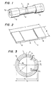
- a pipe 1 to be manufactured consists of a thinner-walled portion 2 having a thickness t 1 and an externally protruding thicker-walled portion 3 having a thickness t 2 , as shown in Fig. 1.
- a material plate 4 having a thinner portion 5 and a thicker portion 6, as shown in Fig. 2 is prepared first.
- the thicknesses of the thinner and thicker portions 5 and 6 of the material plate 4 are respectively equal to those of the thinner- and thicker-walled portions 2 and 3 of the pipe 1, with the length L of the plate being equal to the length of the differential-thickness pipe 1.
- the plate width B can be adjusted by either method I or method II as described below, both of which involve an end-facing process.
- Method I The edges of the thinner and thicker portions 5 and 6 are cut and machined to different widths so that the desired outside diameters will be obtained.
- Method II The material plate is cut to a width B that is sufficiently large enough to obtain the desired outside diameter.
- method I is applicable to thinner plates
- method II is suited for heavier plates and pipes calling for stricter diametrical accuracy.
- Such a metal plate as is thicker at both ends than in the middle can be prepared by passing a slab of uniform thickness through a reversing plate mill and giving a reversed rolling midway in the final pass. The thicker portion at both ends is then levelled by either pressing or machining so that one surface of the plate forms a continuous, flush plane throughout.
- the relationship between the plate width B (or the peripheral length of the circle defined by the neutral plane) and the peripheral length of the pipe varies with the strength of plate, curvature of bend and other factors. Therefore, it is not easy to provide a plate 4 having a thicker portion 6 and a thinner portion 5 with such a width B as can ensure attainment of the desired peripheral lengths in both portions. If the differential-thickness pipe 1 having an inside radius Ri as shown in Fig.
- the circumferential distortion across the plate thicknesses in the heavier and lighter portions 3 and 2 will be compressive and elongated on the inside and outside of the neutral plane N, respectively, as illustrated.
- the distortions at the internal and external surfaces of the thicker-walled portion 3 will then be ⁇ 1 and + ⁇ 2 .
- a uniform circumferential elongation I must be provided across the thickness of the heavier-wall portion 3 so that the neutral plane of the thicker-walled portion agrees with that of the thinner-walled portion. Because of the longitudinally differentiated wall thicknesses and relatively different cross-sectional areas of the two portions, however, it is difficult to cause the piece being bent to simultaneously undergo such a uniform elongation. Therefore, the uniform elongation in the thicker-walled portion 3 is usually smaller than I.
- the actual outside diameter of the thicker-walled portion 3 of the differential-thickness pipe 1 is smaller than the aimed-for value, and the inside diameter of the thicker-walled portion 3 does not agree with that of the thinner-walled portion 2.
- the net result is that the differential-thickness pipe 1 of the desired size cannot be made from the plate 4 having a uniform width B throughout the length thereof. Accordingly, it becomes necessary to provide different widths B i and B 2 as in the thinner and thicker portions 8 and 9 shown in Fig.
- D 1 and D 2 are the desired outside diameters of the thinner- and thicker-walled portions 2 and 3
- t 1 and t 2 are the wall thicknesses thereof
- b 1 and b 2 are the values used to correct changes in the elongation at the external surface of the pipe that might arise when the neutral plane N, in which no forming-induced circumferential elongation occurs, is not positioned just at the center (1/2) of the plate width.
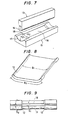
- the transition portion 10 where plate thickness changes may be defined by one of three cut-off lines shown in Fig. 5.
- the inclined portion of the cut-off line (a) connects the thinner- and thicker-walled portions in such a manner as to conform to a change in pipe wall thickness.
- the inclined portion of the cut-off line (b) essentially agrees with that of the cut-off line (a) except that each end thereof consists of an arc contacting the horizontal and inclined portions of the cut-off line (a) so that the thinner- and thicker-walled portions are connected more smoothly.
- the inclined portion of the cut-off line (c) is more gently sloped than that of cut-off line (a) and consists of a middle straight portion and an arc contacting each end of the straight portion and the horizontal portion thereof. Unnecessary portion is cut off along the chosen line.
- the plate width in the transition portion 10 should be changed gradually along the cut-off line (c).
- the resulting transition portion will affect the adjoining areas. More specifically, the outside diameter in the adjoining areas too will vary. In determining the plate width taper, therefore, allowance should be made for such an effect.
- both edges are brought together for tack welding, an opening left therebetween varies so widely from one point to another that great force will have to be exerted to butt together both edges evenly.
- the pipe itself might even deform before both edges thereof have been properly butted together. It is therefore desirable to change the plate width as gradually as along the cut-off line (c).
- the contour of the plate edges is not limited to any specific one shape, but, rather, can be chosen in accordance with the accuracy with which pipe diameter is determined, plate edges being set end to end and butt-welded together.
- Both edges of the width-adjusted plate are machined to form, for instance, a ' double V-groove when they are butted together by bending. Edge preparation is accomplished by fusing and machining.
- Fig. 7 shows a punch 13 and a die 15 of a press bender.
- the pressing end 14 of the punch 13 is smoothly curved, with the radius of curvature R 1 thereof being made equal to or smaller than the inside radius of the differential-thickness pipe 1 to be manufactured.
- the radius of curvature R 2 of a portion 16 of the die 15 that corresponds to the thinner-walled portion 2 of the pipe is equal to or slightly smaller than the outside radius of the thinner-walled portion 2
- the radius of curvature R 3 of a portion 17 corresponding to the thicker-walled portion 3 is equal to or slightly smaller than the outside radius of the thicker-walled portion 3.
- a transition portion 18 where the die profile changes gradually in order to avoid an abrupt change in the resulting pipe wall thickness.
- the original plate width B is provided with an ample margin that is cut off later after the forming operation has proceeded to some extent.
- the plate width B n(D 2- t,)+b.
- the margin b (0.5 to 2)t 2 .
- the unnecessary portion is cut off not only for the adjustment of plate width but also for minimizing the out-of-roundness of the formed pipe as the edge portions, if left unremoved, are usually difficult to bend smoothly.
- the cut-off line 19 on the tubular piece curves throughout the length thereof as shown in Fig. 9 and cutting therealong is not an easy job. But the cutting operation can be made easier by making the curved cut-off line 19 close to a straight line.
- This correction can be achieved by adjusting the widths W 1 and W 2 of openings in the thinner- and thicker-walled portions 2 and 3 using a press 22 or other appropriate tool, with a liner 21 inserted in an opening 20 in the thicker-walled portion 3 as shown in Fig. 10.
- the insides of the thicker- and thinner-walled portions are both bent to a substantially uniform radius of curvature.
- the tubularly formed piece springs back less in the thicker-walled portion than in the thinner-walled portion, with the result that the ultimate radius of curvature of the thicker-walled portion becomes smaller than that in the thinner-walled portion and, therefore, the opening between the butted edges varies greatly between the two portions as shown in Fig. 6.
- this problem can be solved by using a punch 23 whose radius of curvature in a portion 24 ⁇ orresponding.to the thinner-walled portion of the pipe is made smaller than that in a portion 25 corresponding to the thicker-walled portion in accordance with the differences in the plate thickness, desired curvature and amount of springback between the two portions.
- Using the punch 23 of this type of design facilitates the forming for final butting and enhances the accuracy of tack welding.
- the curvature in said two portions may be varied either by machining the individual portions differently or by finishing the punch to the curvature of the thinner-walled portion throughout the entire length thereof and then attaching a liner only to the thicker-walled portion.
- both edges of the plate must be brought into uniform contact with each other over the entire length thereof. In some instances, however, such a uniform contact can not be attained. With ordinary tools, it is sometimes difficult to form the material plate into such tubular shape as can meet exacting diametrical accuracy specification. These difficulties, however, can be overcome by use of cramp-type dies as shown in Figs 12(a) and 12(b).
- the cramp-type die 26 with a smoothly curved working surface, shown in Fig. 12(a) covers the periphery of a tubular piece 27, thereby butting together both edges thereof without causing deformation.
- a simpler toot 28 having a gently tapered V groove 29, as shown in Fig. 12(b), or a liner may also prove useful.
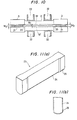
- Fig. 13 shows a double-side differential-thickness plate 30 whose thicker portion corresponding to the thicker-walled portion of a pipe protrudes not only externally but also internally. While being bent by the pushing end 14 of the punch 13 shown in Fig. 7, the thicker portion 32 of the plate 30 is pushed outward.
- This method permits using double-side differential-thickness plates as rolled, thereby saving the trouble of preparing one-side differential-thickness plates by machining off the projection on one side thereof.
- Tubular forming can be accomplished not only by press bending as in the cases described in the foregoing but also by roll bending.
- Fig. 14 shows an example of a roll arrangement and roll profiles on a three-piece roll bender.
- a reduction work roll 35 and two fixed rolls 36 and 37 are arranged in a pyramidal or triangular cluster.
- the material plate is bent when passing through the clearance between the reduction roll 35 and the fixed rolls 36 and 37.
- the fixed rolls 36 and 37 each have grooves 38 in the positions corresponding to the thicker-walled portion of the pipe.
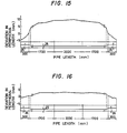
- Differential-thickness pipes each having an overall length of 6000 mm were made using two different methods.
- the pipes were desired to have an inside diameter of 450 mm, a thinner-walled portion having an outside diameter of 500 mm and a wall thickness of 25 mm, a 50 mm long transition portion on each side of the thinner-walled portion, and a 300 mm long thicker-walled portion with an outside diameter of 520 mm and a wall thickness of 35 mm on the outside of each transition portion.
- a pipe of the above specification was made from a 6000 mm long by 1508 mm wide plate with a 40 kg/mm class yield strength that had a thinner portion 25 mm thick, a thicker portion 35 mm thick and 300 mm long, and transition portions 50 mm long each.
- the obtained differential-thickness pipe did not have good dimensional accuracy, with the peripheral length deviation (measured length minus target length) varying greatly as shown in Fig. 15.
Landscapes
- Engineering & Computer Science (AREA)
- Mechanical Engineering (AREA)
- Bending Of Plates, Rods, And Pipes (AREA)
Description
- This invention relates to a method of manufacturing a metal pipe with longitudinally differentiated wall thickness.
- Recently, exploitation of offshore oil fields (including gas fields) has been carried out at increasingly greath depths. Fixed drilling platforms fastened to the seabed used to be the main equipment employed in oil and gas prospecting and exploitation. The need to work in deeper water has brought about the evolution of flexible- structure drilling platforms. One example is a tension-leg platform.
- The tension-leg platform is a floating drilling platform that is secured to its anchoring members on the sea floor by means of the so-called tension legs comprising a number of steel tubular members screwed together. Usually, each tubular member is approximately 12 m long, having an external thread (a pin section) and an internal thread (a box section) cut at each end thereof. The pin and box sections are also generically called connector sections. To ensure adequate strength, the threaded connector sections at both ends are greater in wall thickness than elsewhere. While in service, drilling platforms are subjected to ever- changing forces exerted by winds, waves, currents and tides. So, the tubular members are required to have high enough fatique strength to endure the stresses induced by such forces under seawater.
- In manufacturing the tubular tension legs, the conventional practice has been to form the connector sections or the pin and box sections by forging (see e.g. M. M. Slama, J. H. Petlo, Selection and Evaluation of High Strength Steel for Hutton TLP Tension Leg Elements, OTC 4449 (1983)). With the pipe having longitudinally differentiated wall thickness or outside diameter, however, such forging is not only time-consuming but also uneconomical because of the need to finish with machining.
- An object of this invention is to provide an inexpensive method of manufacturing a metal pipe with longitudinally differentiated wall thickness with high dimensional accuracy by bending and welding, instead of forging.
- This object is achieved by the method according to claim 1.
- To implement the method of this invention, a rectangular metal plate has to be prepared, with a portion corresponding to the thicker-waited portion of the finished pipe having greater thickness than a portion corresponding to the thinner-walled portion. Such a metal plate as is thicker at both ends than in the middle can be prepared by passing a slab of uniform thickness through a reversing plate mill and giving a reversed rolling midway in the final pass. The thicker portion at both ends is then levelled by either pressing or machining so that one surface of the plate forms a continuous, flush plane throughout.
- Before being bent thoroughly until both edges meet to form a tubular shape, the middle portion of the material plate corresponding to the thinner-walled portion is partly cut away to make the width thereof smaller than that of both ends corresponding to the thicker-walled portion, thereby ensuring that the finished pipe will attain a periphery of the desired length. This width adjustment is done before the forming operation is started, or after both edges have been preformed, or after the material plate has been nearly formed into a complete circle.
- The width-adjusted material plate is then bent until both edges meet to form a tubular shape either by punch-and-die pressing or roll-bending.
- On welding the butted edges, a metal pipe with longitudinally differentiated wall thickness is completed.
-
- Fig. 1 is a perspective view of a metal pipe with longitudinally differentiated wall thickness manufactured by the method of this invention;
- Fig. 2 is a perspective view of a material plate before being bent;
- Fig. 3 is a cross-sectional view of a metal pipe with longitudinally differentiated wall thickness;
- Fig. 4 is a plan view of a material plate with longitudinally differentiated thickness, with a portion of both edges thereof cut away;
- Fig. 5 shows the line along which said edge cutting is done in the thickness-changing region between the thicker and thinner-walled portions of the material plate or pipe;
- Fig. 6 is a top view of a tubular product immediately after the bending operation;
- Fig. 7 is a perspective view showing an example of a punch and die of a press bender used in the bending operation;
- Fig. 8 is a perspective view of a material plate immediately after the edge-forming operation;
- Fig. 9 is another top view of a tubular product immediately after the bending operation;
- Fig. 10 is a top view of a tubular product with a liner inserted in the opening therein;
- Figs. 11 (a) and 11 (b) are a perspective view and a front view of a bending punch having different curvatures for the thicker and thinner portions;
- Figs. 12(a) and 12(b) are front views showing cramp-type bending tools;
- Fig. 13 is a perspective view of a material plate, still unbent, with longitudinally differentiated thickness;
- Fig. 14 is a perspective view of an example of a roll cluster of a roll bender used for the bending operation;
- Fig. 15 is a graph of measured deviations in the peripheral length of a differential-thickness pipe made from a material plate with longitudinally differentiated thickness and uniform width; and
- Fig. 16 is a graph of measured deviations in the peripheral length of a differential-thickness pipe more accurately made by the method of this invention.
- A pipe 1 to be manufactured consists of a thinner-walled
portion 2 having a thickness t1 and an externally protruding thicker-walled portion 3 having a thickness t2, as shown in Fig. 1. - In making a metal pipe 1 with longitudinally differentiated wall thickness (hereinafter called the differential-thickness pipe), a
material plate 4 having athinner portion 5 and athicker portion 6, as shown in Fig. 2, is prepared first. The thicknesses of the thinner andthicker portions material plate 4 are respectively equal to those of the thinner- and thicker-walled portions - The plate width B can be adjusted by either method I or method II as described below, both of which involve an end-facing process.
- Method I: The edges of the thinner and
thicker portions - Method II: The material plate is cut to a width B that is sufficiently large enough to obtain the desired outside diameter.
- The choice between the two methods depends upon the wall thickness and desired accuracy of the pipe to be made. Generally, method I is applicable to thinner plates, whereas method II is suited for heavier plates and pipes calling for stricter diametrical accuracy.
- Such a metal plate as is thicker at both ends than in the middle can be prepared by passing a slab of uniform thickness through a reversing plate mill and giving a reversed rolling midway in the final pass. The thicker portion at both ends is then levelled by either pressing or machining so that one surface of the plate forms a continuous, flush plane throughout.
- A detailed description of the two plate width adjusting methods is given below.
- Let us assume that a circle defined by the neutral plane N in the
thinner portion 2 of a differential-thickness pipe 1 shown in Fig. 3 has a radius r, then the required plate width B is determined as 2nr (B=2nr) based on the peripheral length of the pipe. Actually, however, the relationship between the plate width B (or the peripheral length of the circle defined by the neutral plane) and the peripheral length of the pipe varies with the strength of plate, curvature of bend and other factors. Therefore, it is not easy to provide aplate 4 having athicker portion 6 and athinner portion 5 with such a width B as can ensure attainment of the desired peripheral lengths in both portions. If the differential-thickness pipe 1 having an inside radius Ri as shown in Fig. 3 is obtained from a plate of uniform width B, the circumferential distortion across the plate thicknesses in the heavier andlighter portions portion 3 will then be ―ε1 and +ε2 . Accordingly, a uniform circumferential elongation I must be provided across the thickness of the heavier-wall portion 3 so that the neutral plane of the thicker-walled portion agrees with that of the thinner-walled portion. Because of the longitudinally differentiated wall thicknesses and relatively different cross-sectional areas of the two portions, however, it is difficult to cause the piece being bent to simultaneously undergo such a uniform elongation. Therefore, the uniform elongation in the thicker-walledportion 3 is usually smaller than I. - As a consequence, the actual outside diameter of the thicker-
walled portion 3 of the differential-thickness pipe 1 is smaller than the aimed-for value, and the inside diameter of the thicker-walled portion 3 does not agree with that of the thinner-walled portion 2. The net result is that the differential-thickness pipe 1 of the desired size cannot be made from theplate 4 having a uniform width B throughout the length thereof. Accordingly, it becomes necessary to provide different widths Bi and B2 as in the thinner andthicker portions 

walled portions - The
transition portion 10 where plate thickness changes may be defined by one of three cut-off lines shown in Fig. 5. The inclined portion of the cut-off line (a) connects the thinner- and thicker-walled portions in such a manner as to conform to a change in pipe wall thickness. The inclined portion of the cut-off line (b) essentially agrees with that of the cut-off line (a) except that each end thereof consists of an arc contacting the horizontal and inclined portions of the cut-off line (a) so that the thinner- and thicker-walled portions are connected more smoothly. The inclined portion of the cut-off line (c) is more gently sloped than that of cut-off line (a) and consists of a middle straight portion and an arc contacting each end of the straight portion and the horizontal portion thereof. Unnecessary portion is cut off along the chosen line. - Preferably, the plate width in the
transition portion 10 should be changed gradually along the cut-off line (c). When a plate having differentiated thicknesses is cut along the line (a) or (b), the resulting transition portion will affect the adjoining areas. More specifically, the outside diameter in the adjoining areas too will vary. In determining the plate width taper, therefore, allowance should be made for such an effect. When both edges are brought together for tack welding, an opening left therebetween varies so widely from one point to another that great force will have to be exerted to butt together both edges evenly. The pipe itself might even deform before both edges thereof have been properly butted together. It is therefore desirable to change the plate width as gradually as along the cut-off line (c). - The contour of the plate edges, however, is not limited to any specific one shape, but, rather, can be chosen in accordance with the accuracy with which pipe diameter is determined, plate edges being set end to end and butt-welded together.
- Both edges of the width-adjusted plate are machined to form, for instance, a' double V-groove when they are butted together by bending. Edge preparation is accomplished by fusing and machining.
- The
material plate 7 thus prepared is bent into tubular form by a press bender. Fig. 7 shows apunch 13 and adie 15 of a press bender. - The
pressing end 14 of thepunch 13 is smoothly curved, with the radius of curvature R1 thereof being made equal to or smaller than the inside radius of the differential-thickness pipe 1 to be manufactured. The radius of curvature R2 of aportion 16 of the die 15 that corresponds to the thinner-walled portion 2 of the pipe is equal to or slightly smaller than the outside radius of the thinner-walled portion 2, whereas the radius of curvature R3 of aportion 17 corresponding to the thicker-walled portion 3 is equal to or slightly smaller than the outside radius of the thicker-walled portion 3. Between theportions transition portion 18 where the die profile changes gradually in order to avoid an abrupt change in the resulting pipe wall thickness. - According to this method, the original plate width B is provided with an ample margin that is cut off later after the forming operation has proceeded to some extent. Here, the plate width B=n(D2-t,)+b. The margin b=(0.5 to 2)t2. Using the press bender shown in Fig. 7, the
material plate 4 thus prepared is first bent only at the edges thereof to form an arched piece as shown in Fig. 8. The piece may also be bent further into a tubular form as shown in Fig. 9. Then, the width B of the bent piece is cut down to widths B1 and B2 so that the peripheral lengths S↑ =πD↑ and S2=πD2 of the thinner- and thicker-walled portions thickness changing portion 12 is determined in the same manner as in Method I in which width adjustment is done while the plate still remains flat. - The unnecessary portion is cut off not only for the adjustment of plate width but also for minimizing the out-of-roundness of the formed pipe as the edge portions, if left unremoved, are usually difficult to bend smoothly.
- The cut-
off line 19 on the tubular piece curves throughout the length thereof as shown in Fig. 9 and cutting therealong is not an easy job. But the cutting operation can be made easier by making the curved cut-off line 19 close to a straight line. This correction can be achieved by adjusting the widths W1 and W2 of openings in the thinner- and thicker-walled portions press 22 or other appropriate tool, with aliner 21 inserted in anopening 20 in the thicker-walled portion 3 as shown in Fig. 10. - With the forming effected by using a longitudinally uniformity contoured
punch 13 as shown in Fig. 7, the insides of the thicker- and thinner-walled portions are both bent to a substantially uniform radius of curvature. Generally, however, the tubularly formed piece springs back less in the thicker-walled portion than in the thinner-walled portion, with the result that the ultimate radius of curvature of the thicker-walled portion becomes smaller than that in the thinner-walled portion and, therefore, the opening between the butted edges varies greatly between the two portions as shown in Fig. 6. - As shown in Figs. 11 (a) and 11 (b), this problem can be solved by using a
punch 23 whose radius of curvature in aportion 24 αorresponding.to the thinner-walled portion of the pipe is made smaller than that in aportion 25 corresponding to the thicker-walled portion in accordance with the differences in the plate thickness, desired curvature and amount of springback between the two portions. Using thepunch 23 of this type of design facilitates the forming for final butting and enhances the accuracy of tack welding. The curvature in said two portions may be varied either by machining the individual portions differently or by finishing the punch to the curvature of the thinner-walled portion throughout the entire length thereof and then attaching a liner only to the thicker-walled portion. - For the achievement of butt welding, both edges of the plate must be brought into uniform contact with each other over the entire length thereof. In some instances, however, such a uniform contact can not be attained. With ordinary tools, it is sometimes difficult to form the material plate into such tubular shape as can meet exacting diametrical accuracy specification. These difficulties, however, can be overcome by use of cramp-type dies as shown in Figs 12(a) and 12(b). The cramp-type die 26 with a smoothly curved working surface, shown in Fig. 12(a), covers the periphery of a
tubular piece 27, thereby butting together both edges thereof without causing deformation. Asimpler toot 28 having a gently taperedV groove 29, as shown in Fig. 12(b), or a liner may also prove useful. - Fig. 13 shows a double-side differential-
thickness plate 30 whose thicker portion corresponding to the thicker-walled portion of a pipe protrudes not only externally but also internally. While being bent by the pushingend 14 of thepunch 13 shown in Fig. 7, thethicker portion 32 of theplate 30 is pushed outward. This method permits using double-side differential-thickness plates as rolled, thereby saving the trouble of preparing one-side differential-thickness plates by machining off the projection on one side thereof. - Tubular forming can be accomplished not only by press bending as in the cases described in the foregoing but also by roll bending. Fig. 14 shows an example of a roll arrangement and roll profiles on a three-piece roll bender. A
reduction work roll 35 and two fixedrolls reduction roll 35 and the fixed rolls 36 and 37. The fixed rolls 36 and 37 each havegrooves 38 in the positions corresponding to the thicker-walled portion of the pipe. - Differential-thickness pipes each having an overall length of 6000 mm were made using two different methods. The pipes were desired to have an inside diameter of 450 mm, a thinner-walled portion having an outside diameter of 500 mm and a wall thickness of 25 mm, a 50 mm long transition portion on each side of the thinner-walled portion, and a 300 mm long thicker-walled portion with an outside diameter of 520 mm and a wall thickness of 35 mm on the outside of each transition portion.
- Using a press bender, a pipe of the above specification was made from a 6000 mm long by 1508 mm wide plate with a 40 kg/mm class yield strength that had a
thinner portion 25 mm thick, athicker portion 35 mm thick and 300 mm long, and transition portions 50 mm long each. The obtained differential-thickness pipe did not have good dimensional accuracy, with the peripheral length deviation (measured length minus target length) varying greatly as shown in Fig. 15. - By contrast, another differential-thickness pipe was made by using a 1580 mm wide plate whose edges were cut away by fusing, in accordance with the method of this invention, so that the desired peripheral length would be obtained after the forming operation has proceeded to some extent. As a result, a differential-thickness pipe of good dimensional accuracy could be obtained. The peripheral length deviation of this pipe is shown in Fig. 16.
Claims (8)
Applications Claiming Priority (10)
| Application Number | Priority Date | Filing Date | Title |
|---|---|---|---|
| JP145637/83 | 1983-08-11 | ||
| JP145639/83 | 1983-08-11 | ||
| JP14563783A JPS6037219A (en) | 1983-08-11 | 1983-08-11 | Manufacture of metallic pipe having wall-thickness difference in its longitudinal direction |
| JP14563983A JPH0245524B2 (en) | 1983-08-11 | 1983-08-11 | KANNAGATEHOKONINIKUATSUSAOMOTSUTAKINZOKUKANNOSEIZOHOHO |
| JP14563883A JPS6037220A (en) | 1983-08-11 | 1983-08-11 | Manufacture of metallic pipe having wall-thickness difference in its longitudinal direction |
| JP145638/83 | 1983-08-11 | ||
| JP5516/84 | 1984-01-18 | ||
| JP551684A JPS60152319A (en) | 1984-01-18 | 1984-01-18 | Manufacture of metallic pipe having thickness difference in longitudinal direction of pipe |
| JP5517/84 | 1984-01-18 | ||
| JP551784A JPS60152320A (en) | 1984-01-18 | 1984-01-18 | Manufacture of metallic pipe having thickness difference in longitudinal direction of pipe |
Publications (2)
| Publication Number | Publication Date |
|---|---|
| EP0133705A1 EP0133705A1 (en) | 1985-03-06 |
| EP0133705B1 true EP0133705B1 (en) | 1987-10-28 |
Family
ID=27518611
Family Applications (1)
| Application Number | Title | Priority Date | Filing Date |
|---|---|---|---|
| EP84109549A Expired EP0133705B1 (en) | 1983-08-11 | 1984-08-10 | Method of manufacturing metal pipe with longitudinally differentiated wall thickness |
Country Status (3)
| Country | Link |
|---|---|
| US (1) | US4603806A (en) |
| EP (1) | EP0133705B1 (en) |
| DE (1) | DE3466942D1 (en) |
Cited By (2)
| Publication number | Priority date | Publication date | Assignee | Title |
|---|---|---|---|---|
| DE10316336A1 (en) * | 2003-04-10 | 2004-11-04 | Dreistern-Werk Maschinenbau Gmbh & Co. Kg | Method and device for producing a closed metal profile or metal tube with wall thickness varying in the longitudinal direction |
| DE102004017343A1 (en) * | 2004-04-06 | 2005-11-03 | Muhr Und Bender Kg | Method for producing profiles with a longitudinally variable cross section |
Families Citing this family (29)
| Publication number | Priority date | Publication date | Assignee | Title |
|---|---|---|---|---|
| BR9300271A (en) * | 1993-01-25 | 1993-08-03 | Maria Eliane Almeida | DEVICE FOR FIXING THERMAL INSULATION IN PIPES AND THERMAL INSULATION SYSTEM USING THAT DEVICE |
| DE19604357B4 (en) * | 1996-02-07 | 2004-06-24 | Benteler Ag | Process for the production of pipes with sections of different wall thickness |
| US5727419A (en) * | 1996-09-26 | 1998-03-17 | Applied Power Inc. | Tube bender handle |
| NL1014823C2 (en) * | 2000-04-03 | 2001-10-04 | Corus Staal Bv | Method of manufacturing a tubular part. |
| DE10041281C2 (en) * | 2000-08-22 | 2002-07-11 | Muhr & Bender Kg | Device for forming blanks from flexibly rolled metal strip |
| JP2002153930A (en) * | 2000-09-06 | 2002-05-28 | Toyota Motor Corp | Hollow member, method of manufacturing the same, fluid circulation system using the hollow member, and apparatus for forming hollow material |
| DE10048312B4 (en) * | 2000-09-29 | 2004-07-29 | Benteler Ag | ironing apparatus |
| US6548760B1 (en) * | 2000-12-11 | 2003-04-15 | Eastern Sheet Metal, Inc. | One-piece seamless reducer |
| DE10063040C2 (en) * | 2000-12-18 | 2002-10-24 | Benteler Automobiltechnik Gmbh | Process for the production of boards which vary in thickness in some areas |
| DE10210156A1 (en) * | 2002-03-07 | 2003-09-25 | Bayerische Motoren Werke Ag | Method of producing tubular body in sections with differing thickness involves bending the tube and welding it |
| JP4394864B2 (en) * | 2002-05-07 | 2010-01-06 | テルモ株式会社 | Metal tubular body and manufacturing method thereof |
| US20040250404A1 (en) * | 2003-01-14 | 2004-12-16 | Cripsey Timothy J. | Process for press forming metal tubes |
| DE10323693B3 (en) * | 2003-05-22 | 2004-09-09 | Muhr Und Bender Kg | Sheet element from flexible rolled strip for vehicle components is formed into variable wall thickness over its length, producing tubes or strip of non-round cross section |
| DE10329424B4 (en) * | 2003-07-01 | 2005-04-28 | Thyssenkrupp Stahl Ag | Method for producing a longitudinally slotted hollow profile with a plurality of longitudinal sections, which are different in cross-section, from a planar sheet metal blank |
| US8235628B2 (en) * | 2005-03-17 | 2012-08-07 | Kellogg Brown & Root Llc | Continuously pressurized pipeline |
| FR2973490B1 (en) * | 2011-03-31 | 2018-05-18 | Valeo Systemes Thermiques | THERMAL EXCHANGER TUBE, HEAT EXCHANGER AND CORRESPONDING PROCESSING METHOD |
| US9528327B1 (en) | 2011-09-23 | 2016-12-27 | Global Tubing Llc | Coiled tubing optimized for long, horizontal completions |
| JP5800030B2 (en) | 2011-12-21 | 2015-10-28 | Jfeスチール株式会社 | Strip metal plate |
| CN103286158B (en) * | 2012-02-29 | 2016-06-22 | 宝山钢铁股份有限公司 | Two one-step forming methods are utilized to prepare method and the device of not uniform thickness vertical masonry joint laser welding pipe |
| RU2572940C1 (en) * | 2012-04-02 | 2016-01-20 | ДжФЕ СТИЛ КОРПОРЕЙШН | Welded steel large-diameter pipe produced by uoe process and its structure |
| US20140041230A1 (en) * | 2012-08-08 | 2014-02-13 | Krip Llc | Fabrication member |
| CN102847743A (en) * | 2012-09-20 | 2013-01-02 | 上海和达汽车配件有限公司 | Manufacture method of pipe different in wall thickness |
| CN103506425A (en) * | 2013-10-15 | 2014-01-15 | 赵建军 | Preparation method of square steel pipes with different wall thicknesses |
| CN104772566A (en) * | 2014-01-10 | 2015-07-15 | 宝山钢铁股份有限公司 | Processing method for non-uniform thickness welded pipe |
| FR3016619B1 (en) * | 2014-01-17 | 2016-08-19 | Gaztransport Et Technigaz | THERMALLY INSULATING, WATERPROOF TANK WITH METAL BANDS |
| US10207371B1 (en) | 2016-09-13 | 2019-02-19 | Hanger & Pipe Accessories, Inc. | Methods and systems for making poison pads |
| JP7050737B2 (en) * | 2019-10-30 | 2022-04-08 | フタバ産業株式会社 | How to make a pipe |
| CN112894184B (en) * | 2020-12-28 | 2022-04-15 | 华能山东发电有限公司众泰电厂 | Automatic control device for butt joint length of net rack rod pieces |
| US20220371068A1 (en) * | 2021-05-24 | 2022-11-24 | Metal Forming & Coining Corporation | Shaft assembly and method of producing the same |
Family Cites Families (10)
| Publication number | Priority date | Publication date | Assignee | Title |
|---|---|---|---|---|
| US379026A (en) * | 1888-03-06 | Manufacture of wagon-skeins | ||
| US1310130A (en) * | 1919-07-15 | Method oe producing metal tubes | ||
| US653903A (en) * | 1900-01-18 | 1900-07-17 | Nat Tube Co | Method of forming wrought-metal bands. |
| US1623064A (en) * | 1925-06-10 | 1927-04-05 | James W Napier | Coupling and method of making the same |
| US1978685A (en) * | 1930-06-16 | 1934-10-30 | Clark Equipment Co | Method of making rear axle housings |
| US2104688A (en) * | 1934-10-01 | 1938-01-04 | Alvin L Johnson | Method of making threaded tubes |
| US2286971A (en) * | 1939-12-02 | 1942-06-16 | Murray Mfg Corp | Hollow shell |
| JPS6044050B2 (en) * | 1976-09-10 | 1985-10-01 | 新日本製鐵株式会社 | Multi-stage forming method for long shells |
| SU761071A1 (en) * | 1978-10-13 | 1980-09-07 | Kb Aviat Z | METHOD OF MANUFACTURING DETAILS FROM PRESSED PROFILES 1 |
| JPS58221616A (en) * | 1982-06-16 | 1983-12-23 | Sumitomo Metal Ind Ltd | Manufacture of welded steel pipe with uneven thickness |
-
1984
- 1984-08-07 US US06/638,615 patent/US4603806A/en not_active Expired - Fee Related
- 1984-08-10 EP EP84109549A patent/EP0133705B1/en not_active Expired
- 1984-08-10 DE DE8484109549T patent/DE3466942D1/en not_active Expired
Non-Patent Citations (1)
| Title |
|---|
| "Selection and Evaluation of High Strenght Steel for Hutton TLP Leg Elements", M.M. Slana, J.H. Perls, Offshire Technology Conference, Houston, Texas, 1983 * |
Cited By (3)
| Publication number | Priority date | Publication date | Assignee | Title |
|---|---|---|---|---|
| DE10316336A1 (en) * | 2003-04-10 | 2004-11-04 | Dreistern-Werk Maschinenbau Gmbh & Co. Kg | Method and device for producing a closed metal profile or metal tube with wall thickness varying in the longitudinal direction |
| DE102004017343A1 (en) * | 2004-04-06 | 2005-11-03 | Muhr Und Bender Kg | Method for producing profiles with a longitudinally variable cross section |
| DE102004017343A8 (en) * | 2004-04-06 | 2006-02-23 | Muhr Und Bender Kg | Method for producing profiles with a longitudinally variable cross section |
Also Published As
| Publication number | Publication date |
|---|---|
| DE3466942D1 (en) | 1987-12-03 |
| EP0133705A1 (en) | 1985-03-06 |
| US4603806A (en) | 1986-08-05 |
Similar Documents
| Publication | Publication Date | Title |
|---|---|---|
| EP0133705B1 (en) | Method of manufacturing metal pipe with longitudinally differentiated wall thickness | |
| US6148654A (en) | Convertible roll forming apparatus | |
| CA2967914C (en) | Method of producing steel pipe and press die used for same | |
| GB1562847A (en) | Method and apparatus for manufacturing metal pipe | |
| US4294095A (en) | Process for fabricating heavy wall to pipe | |
| JP2871532B2 (en) | Manufacturing method of UO steel pipe | |
| JP6566232B1 (en) | Steel plate end bending method and apparatus, and steel pipe manufacturing method and equipment | |
| RU2057603C1 (en) | Method of making straight-seam electrically welded large-diameter tubes | |
| JPH0819816A (en) | Production of cylindrical member | |
| KR20010034528A (en) | Tool design for tube cold pilgering | |
| JP4496707B2 (en) | U-press tool and UOE steel pipe manufacturing method | |
| JPS6043813B2 (en) | Thick wall UO steel pipe forming method | |
| JP2002178026A (en) | Method of manufacturing UOE pipe | |
| JPS6320609B2 (en) | ||
| EP0133245B1 (en) | A method for forming an electric resistance welded steel pipe | |
| JPH07178402A (en) | Method for manufacturing shaped steel for steel wall | |
| JPS6037219A (en) | Manufacture of metallic pipe having wall-thickness difference in its longitudinal direction | |
| JP2004141936A (en) | Method of manufacturing UOE steel pipe | |
| JPH0394936A (en) | Method for expanding uoe steel pipe | |
| JPH07178411A (en) | Method for manufacturing shaped steel for steel wall | |
| RU2049570C1 (en) | Method for manufacture of welded tubes with longitudinal seam | |
| JPS5976617A (en) | Manufacture of metallic tube having difference of thickness in longitudinal direction | |
| RU2056227C1 (en) | Method for separating pipes into annular billets | |
| CA1239778A (en) | Method for forming an electric resistance welded steel pipe | |
| EP0510759B1 (en) | A method of producing a thin-walled pipe bend |
Legal Events
| Date | Code | Title | Description |
|---|---|---|---|
| PUAI | Public reference made under article 153(3) epc to a published international application that has entered the european phase |
Free format text: ORIGINAL CODE: 0009012 |
|
| AK | Designated contracting states |
Designated state(s): DE FR IT |
|
| 17P | Request for examination filed |
Effective date: 19850423 |
|
| GRAA | (expected) grant |
Free format text: ORIGINAL CODE: 0009210 |
|
| ITF | It: translation for a ep patent filed | ||
| AK | Designated contracting states |
Kind code of ref document: B1 Designated state(s): DE FR IT |
|
| REF | Corresponds to: |
Ref document number: 3466942 Country of ref document: DE Date of ref document: 19871203 |
|
| ET | Fr: translation filed | ||
| PLBE | No opposition filed within time limit |
Free format text: ORIGINAL CODE: 0009261 |
|
| STAA | Information on the status of an ep patent application or granted ep patent |
Free format text: STATUS: NO OPPOSITION FILED WITHIN TIME LIMIT |
|
| 26N | No opposition filed | ||
| ITTA | It: last paid annual fee | ||
| PGFP | Annual fee paid to national office [announced via postgrant information from national office to epo] |
Ref country code: FR Payment date: 19950809 Year of fee payment: 12 Ref country code: DE Payment date: 19950809 Year of fee payment: 12 |
|
| PG25 | Lapsed in a contracting state [announced via postgrant information from national office to epo] |
Ref country code: FR Effective date: 19970430 |
|
| PG25 | Lapsed in a contracting state [announced via postgrant information from national office to epo] |
Ref country code: DE Effective date: 19970501 |
|
| REG | Reference to a national code |
Ref country code: FR Ref legal event code: ST |