EP0133536B1 - Ion sensing electrode and methods for producing such electrodes and ion-selective membranes therefor - Google Patents
Ion sensing electrode and methods for producing such electrodes and ion-selective membranes therefor Download PDFInfo
- Publication number
- EP0133536B1 EP0133536B1 EP19840109062 EP84109062A EP0133536B1 EP 0133536 B1 EP0133536 B1 EP 0133536B1 EP 19840109062 EP19840109062 EP 19840109062 EP 84109062 A EP84109062 A EP 84109062A EP 0133536 B1 EP0133536 B1 EP 0133536B1
- Authority
- EP
- European Patent Office
- Prior art keywords
- tube
- lumen
- ion
- point
- electrode
- Prior art date
- Legal status (The legal status is an assumption and is not a legal conclusion. Google has not performed a legal analysis and makes no representation as to the accuracy of the status listed.)
- Expired
Links
Images
Classifications
-
- B—PERFORMING OPERATIONS; TRANSPORTING
- B29—WORKING OF PLASTICS; WORKING OF SUBSTANCES IN A PLASTIC STATE IN GENERAL
- B29D—PRODUCING PARTICULAR ARTICLES FROM PLASTICS OR FROM SUBSTANCES IN A PLASTIC STATE
- B29D23/00—Producing tubular articles
-
- B—PERFORMING OPERATIONS; TRANSPORTING
- B29—WORKING OF PLASTICS; WORKING OF SUBSTANCES IN A PLASTIC STATE IN GENERAL
- B29D—PRODUCING PARTICULAR ARTICLES FROM PLASTICS OR FROM SUBSTANCES IN A PLASTIC STATE
- B29D99/00—Subject matter not provided for in other groups of this subclass
- B29D99/005—Producing membranes
-
- G—PHYSICS
- G01—MEASURING; TESTING
- G01N—INVESTIGATING OR ANALYSING MATERIALS BY DETERMINING THEIR CHEMICAL OR PHYSICAL PROPERTIES
- G01N27/00—Investigating or analysing materials by the use of electric, electrochemical, or magnetic means
- G01N27/26—Investigating or analysing materials by the use of electric, electrochemical, or magnetic means by investigating electrochemical variables; by using electrolysis or electrophoresis
- G01N27/28—Electrolytic cell components
- G01N27/40—Semi-permeable membranes or partitions
-
- G—PHYSICS
- G01—MEASURING; TESTING
- G01N—INVESTIGATING OR ANALYSING MATERIALS BY DETERMINING THEIR CHEMICAL OR PHYSICAL PROPERTIES
- G01N27/00—Investigating or analysing materials by the use of electric, electrochemical, or magnetic means
- G01N27/26—Investigating or analysing materials by the use of electric, electrochemical, or magnetic means by investigating electrochemical variables; by using electrolysis or electrophoresis
- G01N27/403—Cells and electrode assemblies
- G01N27/4035—Combination of a single ion-sensing electrode and a single reference electrode
-
- B—PERFORMING OPERATIONS; TRANSPORTING
- B29—WORKING OF PLASTICS; WORKING OF SUBSTANCES IN A PLASTIC STATE IN GENERAL
- B29L—INDEXING SCHEME ASSOCIATED WITH SUBCLASS B29C, RELATING TO PARTICULAR ARTICLES
- B29L2031/00—Other particular articles
- B29L2031/755—Membranes, diaphragms
Definitions
- This invention relates to electrodes for measuring ion concentrations in aqueous solutions and to methods of manufacturing such electrodes and the ion-selective membranes they employ.
- lon-sensing electrodes selectively responsive to ionic activities in aqueous solutions are well known to the art.
- the known relationship between ionic activity and ion concentration permits these electrodes to be used to measure ion concentrations.
- selective ion exchange occurs through an interface between a selective ion exchange material and the solution to be sampled.
- Many recent electrode designs have employed ion-selective membranes which retain the ion-selective material in a matrix of organic material such as polyvinylchloride or other plastic.
- the substrate on which the ion-selective membrane is formed is incorporated as part of the electrode structure.
- the membrane is removed from the substrate and attached to the body of the electrode. In such electrodes, sealing of the membrane to the remainder of the electrode structure has been problematic.
- US-A- 4 233 136 addresses the problem of sealing the ion-selective membrane to the remainder of the electrode structure, in the context of incorporating an ion-selective membrane in the wall of a plastic tube.
- This method like that of the prior art electrodes discussed above, involves dissolving powdered plastic in a volatile solvent containing a plasticizer and an ion-selective material and evaporating the solvent to form the membrane.
- a plastic tube is provided with a lateral opening, and a cylindrical mandrel is inserted in the tube across the opening. The mixture is applied to the mandrel, filling the opening of the tube. The volatile solvent fuses the membrane to the plastic tube. After the membrane has formed, the mandrel is removed leaving the membrane in place.
- US-A-3 966 580 discloses a method for producing a protein-immobilizing hydrophobic polymeric membrane by
- a combination ion-sensing and reference electrode is known from GB-A-1 593 270.
- This electrode comprises a bi-lumen tube a first lumen of which is filled with electrolyte and acts as the electrolyte chamber for an ion-sensing electrode.
- the second lumen acts as the electrolyte chamber for a reference electrode, is exposed to a sample solution via an aperture and terminates and is sealed from the first lumen a short distance from the distal end of the tube.
- a porous ceramic or ion-selective glass carrier plug is fitted into the distal end of the tube. The entire surface of the plug extending beyond the distal tube end has an ion-selective plastics based membrane bound thereto by a dip casting procedure.
- the proximal ends of the lumens are sealed by stoppers through which each an electrode extends into the first and second lumen, respectively.
- An object of the present invention is to provide a simplified method of producing ion sensing electrodes and ion-selective membranes adapted for such electrodes, which method allows the use of preformed plastic members as electrolyte chambers with integral ion selective membranes.
- a method for producing an ion sensing electrode of the type including a tube having a proximal end, a distal end, an outer wall and a first lumen, said first lumen filled with an electrolyte gel, having a first electrode within said electrolyte gel, is characterized in that said tube is preformed of a plastic to a desired shape, and in that said method includes the ordered steps of: dissolving an ion selective material in a solvent which is a swelling agent for the plastic of which said tube is fabricated;
- the present invention further provides for an ion sensing electrode, comprising:
- the present invention provides for a method for producing an ion-selective membrane of a desired plastic, having a desired shape, comprising the ordered steps of: dissolving an ion-selective material in a solvent which is also a swelling agent for said desired plastic; subsequently soaking a preformed member fabricated of said desired plastic and having said desired shape, in said solvent until said member swells; and subsequently removing said solvent from said member.
- a tubular structure including an ion-selective membrane may more easily be produced as compared to the methods used to fabricate prior art electrodes.
- This method has as a major advantage that it allows the use of pre-formed, commercially available plastic products, such as single and bi-lumen tubing, to easily and simply fabricate a variety of ion-sensing electrodes. Because the plastic member is first formed to the desired shape and subsequently treated to transform a portion of the member into an ion-selective membrane, the membrane is continuous with an integral to the member and the problem of sealing the membrane to the electrode can be avoided.
- electrodes formed using the methods set forth herein are believed superior to prior art electrodes in that their ion-selective membranes are integral to the electrode structures.
- One preferred embodiment of an electrode according to the present invention uses single lumen polymer tubing to produce a simple ion-sensing electrode.
- Other preferred embodiments employ bi-lumen tubing to produce combination ion-sensing and reference electrodes adapted to be dipped into the sample solution.
- Yet other preferred embodiments employ bi-lumen tubing to easily produce ion-sensing and combination-sensing and reference flow through electrodes.
- the present invention allows all of the described embodiments to be easily produced relative to prior art electrodes.
- each described embodiment has unique and valuable features that are described in detail below.
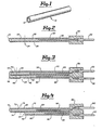
- Fig. 1 shows a tubular plastic member 10 having lumen 12, appropriate for use in fabricating an ion-selective membrane according to the method of the present invention.
- Member 10 may be fabricated of silicone rubber, polyvinylchloride, polyurethane, or other swellable plastic.
- the following steps must be performed. First, member 10 must be soaked in whale or in part in a solvent in which the desired ion-selective material has been dissolved and which acts as a swelling agent for the plastic of which member 10 is constructed. Soaking should continue until member 10 has swelled, indicating incorporation of the ion-selective material. Subsequently, the solvent is removed, leaving behind the ion-selective material and allowing the swelling of member 10 to subside. Preferbaly, the solvent used should be volatile so that it may be conveniently removed by evaporation.
- FIG. 2 illustrates a side cross sectional view of an ion-sensing electrode according to the present invention.
- the ion-selective membrane of the electrode is fashioned from plastic tube 20, which has outer wall 22 impregnated with an ion-selective material, as described above.
- the lumen 36 of tube 20 is filled with an electrolyte solution or gel 26.
- the distal end of tube 20 is sealed with plug 24, which may be made of silicone rubber or other suitable material.
- the proximal end of tube 20 is sealed by connector block 20, which may be made of epoxy or other suitable material.
- connector pin 32 mounteded within connector block 30 is connector pin 32 which is crimped to the proximal end of electrode 28.
- Electrode 28 may be a silver/silver chloride reference electrode, well known to the art.
- Connector pin 32 may be made of any conductive metal such as stainless steel.
- Electrolyte 26 may be any suitable electrolyte solution or gel containing chloride ion and the ion to be detected.
- the above electrode is easily fashioned by first treating tube 20 as discussed in conjunction with FIG. 1 above.
- the entire tube may be treated, or only a portion.
- only the portion distal to dotted line 34 may be dipped in the solvent.
- electrolyte 26 should be added.
- the additional steps of inserting electrode 28 and plug 24 and attaching connector block 30 and pin 32 may be performed in any convenient order, and may preceed the impregnation of tube 20 with the ion-selective material. Because the electrolyte chamber for the sensing electrode is fashioned integrally with the ion-selective membrane, production of the electrode of FIG 2 is considerably simplified as compared to the prior art.
- Silicone rubber tubing of the type manufactured by Dow-Corning Chemical Co., commercially available under the trademark Silastic @ was soaked in a solution of 10 mg of ammonium ion-selective material, Nonactin, an antibiotic, available from Sigma Chemical Co. of St. Louis, Missouri, dissovled in 2.3 ml of methylene chloride, until the tubing swelled. The tubing was removed from the solution and allowed to dry until it returned to its original dimensions. Three such ammonium ion-selective membranes - were incorporated in ion-sensing electrodes as illustrated in FIG. 2.
- the ion-sensing electrodes were placed in aqueous solutions having known molar concentrations of ammonium ions, along with a reference electrode, and the voltage differences between the reference and sensing electrodes were observed.
- a membrane selective for potassium ion (K + ) was produced as follows:
- a length of polyvinylchloride tubing was soaked in a solution of 10 mg of the potassium ion-selective material valimomycin dissolved in 2.5 ml dipentyl phthalate (DPP) available from Eastman Kodak Chemical Co., until the tubing swelled. The tubing was removed and dried for 16 hours at 70°C.
- Two such potassium ion-selective membranes were incorporated in ion-sensing electrodes as illustrated in FIG. 2.
- the ion-sensing electrodes were placed in solutions having known concentrations of potassium ions, along with reference electrodes. The voltage differences between the ion-sensing electrodes and the reference electrodes. illustrated in Table 2, indicate that the ion-sensing electrodes were effective for their intended use.
- a membrane selective for the potassium ion (K + ) was produced as follows:
- the ion-sensing electrodes along with a reference electrode were placed in an aqueous solution having a known molar concentration of potassium ions, to which known increments of a .1 M potassium solution were added, and the voltage differences between the reference and sensing electrodes were observed.
- the correlation of the known molarities of the potassium ions with the measured voltage differences illustrated in Table 3, indicates that the ion-sensing electrodes were effective for their intended use.
- Example 2 A length of silicone rubber tubing as described in Example 1, above, was soaked in a solution of one part by volume of the chloride ion-selective material methyl tricapryl ammonium chloride, commercially available from General Mills Co. under the trade designation Aliquat @ to two parts by volume of Xylene. The tubing was soaked for about one day and then vacuum dried. The Xylene was found to come off easily, but a surface residue of Aliquat remained which was removed by washing with additional Xylene. Two such membranes were incorporated in ion-sensing electrodes as illusrated in FIG. 2. These sensing electrodes were placed in aqueous solutions having known concentrations of chloride ion, and tested as described in Examples 1 and 2 above. The results, illustrated in Table 4, indicate that the ion-sensing electrodes were effective for their intended use.
- the chloride ion-selective material methyl tricapryl ammonium chloride commercially available from General Mills Co. under the
- a membrane appropriate for use in a pH sensing electrode was produced as follows:
- a length of silicone rubber tubing as described above was soaked in a solution of one part by volume of tridodecylamine to two parts by volume of Freon until the tubing swelled. The tube was allowed to air dry until it returned to its original dimensions.
- Three such membranes were incorporated in ion sensing electrodes as illustrated in FIG. 2, using a pH4 buffer containing NaCl as an electrolyte. These pH sensing electrodes were placed in solutions having known pH, and tested as described in the examples above. The results, illustrated in Table 5, indicate that the ion-sensing electrodes were effective for their intended use.
- FIG. 3 illustrates a side sectional view of a combination ion-sensing and reference electrode according to the present invention.
- the ion-selective membrane is fashioned from bi-lumen plastic tube 40, of which the portion distal to dotted line 48 is impregnated with an ion-selective material, using the process described above.
- the first lumen 68 of tube 40 is filled with electrolyte 50, and acts as the electrolyte chamber for the ion-sensing electrode.
- Second lumen 66 is filled with electrolyte 52, and acts as the electrolyte chamber for the refernce electrode. Electrolyte 52 is exposed to the sample solution via aperture 64.
- Electrodes 54 and 56 may be silver/ silver chloride reference electrodes, well known to the art.
- Connector pins 60 and 62 may be made of any conductive metal such as stainless steel.
- Electrolytes 50 and 52 should contain silver and chloride ions, along with the ion to be detected. Because electrolyte 52 is exposed to the sample solution, it is desirable that it be a gel electrolyte. A preferred gel is discussed below.
- the above electrode is fashioned by treating tube 40, distil to dotted line 48, as discussed in conjunction with FIG. 1 above, by dipped the distal end of tube 40 into the solvent. Following evaporation of the solvent, electrolyte 50 and 52 should be added.
- the additional steps of inserting electrodes 54 and 56, attaching connector block 58, attached connector pins 60 and 62, inserting plug 46, and forming aperture 64 may be performed in any convenient order, and may preceed the impregnation of tube 40 with the ion-selective material.
- Aperture 64 may be produced by simply placing a hole in a portion of outer tube wall 42, opening lumen 66 to the exterior of tube wall 42 and allowing free migration of ions from the soluton to be tested into electrolyte 52. It is important to note that aperture 64 is located proximal to dotted line 48, and that plug 46 extends proximal to dotted line 48, thereby providing a seal intermediate the electrolyte contained within lumen 66 and the portion of tube 40 which has been impregnated with the ion-selective material. The seal is desirable to prevent migration ions between the lumens which would interfere with the efficiency of the electrode. Because the electrolyte chambers for both the sensing electrode and the reference electrode are fashioned integrally with the ion-selective membrane, production of the electrode of FIG. 3 is considerably simplified as compared to the prior art.
- a combination potassium selective electrode and reference electrode was produced as follows:
- a length of bi-lumen silicone rubber tubing was soaked in a solution of 10 mg valinomycin and 2.5 ml of Xylene until the tubing swelled. The tubing was removed from the solution and allowed to dry until the tubing returned to its original dimensions.
- Combination electrodes as illustrated in FIG. 3 were fabricated from this tubing. The combination electrodes were placed in aqueous solutions having known molar concentrations of potassium ions, and the voltage differences between the potassium sensing electrode and the reference electrode were observed. The correlation of the known molarities of the potassium ion with the measured voltage differences, illustrated in Table 6 indicates that the combination electrodes were effective for their intended use:
- Fig. 4 illustrates a side sectional view of a combination ion-sensing and reference electrode according to the present invention. Like the electrode of FIG. 3, this electrode is fashioned from a bi-lumen plastic tube 70. That portion of tube 70 which is distal to dotted line 78 is impregnated with an ion-selective material.
- lumen 98 which serves as the electrolyte chamber for the ion-sensing electrode, is sealed by means of plug 76, which may be made of silicone rubber or other suitable plastic.
- plug 76 which may be made of silicone rubber or other suitable plastic.
- the distal end of lumen 96 remains open to the exterior of tube 70, via aperture 94.
- Lumen 96 serves as the electrolyte chamber for the reference electrode portion. Electrodeds 84 and 86, connector block 88, and connector pins 90 and 92 are identical to the corresponding elements in FIG. 3, above.
- the above electrode is fashioned by treating bi-lumen tube 70 distal to dotted line 78 as discussed in conjunction with FIG. 1 above. This may be accomplished by dipping only that portion of tube 70 distal to dotted line 78 in the solvent. Following the evaporation of the solvent, electrolyte 80 and 82 should be added. Electrolyte 80 and 82 correspond to electrolyte 50 and 52 of FIG. 3. The additional steps of inserting electrodes 84 and 86, attaching connector block 88, inserting plug 76 and attaching connector pins 90 and 92, may be performed in any convenient order, and may proceed the impregnation of tube 70 with the ion-selective material. It is important to note that lumen 96 does not extend distal to dotted line 78.
- Bi-lumen tube 70 may be conveniently fabricated by removing a portion of the outer tube wall surrounding lumen 96, intermediate the distal end of tube 70 and a point proximal to dotted line 78. Because the electrolyte chambers for both the sensing and reference electrodes are fashioned integrally with the ion-selective membrane, production of the electrode of FIG. 4 is considerably simplified as compared to the prior art.
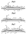
- FIG. 5 illustrates a side sectional view of a flow through ion-sensing electrode.
- the ion-selective membrane of the electrode is fashioned from plastic tube 102, which has outer wall 106 impregnated with an ion-selective material, as described above. Tube 102 also serves as the sample tube for the electrode.
- outer tube 100 Located coaxially around tube 102 is outer tube 100, which may be conveniently made of any appropriate plastic.
- the proximal and distal ends of tube 100 are sealed around tube 102 by means of sealing disks 110 and 112, respectively. That portion of lumen 126 of tube 100 intermediate tube wall 104 of tube 100 and tube wall 106 of tube 102 is filled with electrolyte 114.
- Electrolyte 114 corresponds to electrolyte 26 of FIG. 2.
- the proximal and distal ends of tube 102 are coupled to fluid couplings 118 and 116, respectively.
- Fluid couplings 116 and 118 may be any appropriate fluid coulings adapted for use with plastic or rubber tubing.
- Electrode 122 and connector pin 124 are identical to the corresponding elements in the Figures above.
- Securing connector pin 124 to tube 100 is tubular sleeve 120, which may be fashioned of an appropriate plastic or other material.
- the above electrode is fashioned by first treating tube 102 as discussed in conjunction with FIG. 1 above. The entire tube, or only a portion may be treated. Following evaporation of the solvent, tube 100 and sealing disks 110 and 112 are added. The elctrolyte 114 may then be conveniently added, however, there is no criticality in the order of the steps. The steps of inserting electrode 122 and attaching connector pin 124 and tubular sleeve 120 are similarly not critical to the manufacture of this device. Because the sensing membrane is formed integrally with the sample tube of the flow through electrode, production of the electrode of FIG. 5 is considerably simplified as compared to the prior art.
- FIG. 6 illustrates a side sectional view of a preferred embodiment of a flow-through ion-sensing electrode according to the present invention.
- the ion-selective membrane of the electrode is fashioned from bi-lumen polymer plastic tube 130, which has at least inner wall 134 impregnated with an ion-selective material, as described above.
- Lumen 154 of tube 130 is filled with electrolyte 146, which corresponds to electrolyte 26 of FIG. 2. Sealing the proximal and distal ends respectively of lumen 154 are plugs 136 and 138, which may be conveniently fashioned of silicone rubber or other suitable material.
- Lumen 140 of tube 130 serves as the sample tube for the electrode.
- Fluid couplings 142 and 144 are identical to the corresponding structures shown in FIG. 5.
- Electrode 152, connector pin 150, and tubular sleeve 148 correspond to the' identically named structures in FIG. 5 above.
- the above electrode is fashioned by first treating a bi-lumen tube 130 as discussed in conjunction with FIG. 1 above. The entire tube may be treated, or only a portion thereof. Following the evaporation of the solvent, electrolyte 146 should be added. The additional steps of inserting plugs 136 and 138, inserting electrode 152, attaching circular sleeve 148 and connector pin 150, and inserting fluid couplings 142 and 144 may be performed in any convenient order, and may preceed the impregnation of tube 130 with the ion-selective material. Because the electrolyte chamber and the sample tube of this electrode are fashioned integrally with the ion-selective membrane, production of the electrode of FIG. 6 is considerably simplified as compared to prior art electrodes.
- FIG. 7 illustrates a side sectional view of a combination of ion-sensing and reference flow-through electrodes according to the present invention.
- the ion-selective membrane of the electrode is fashioned from bi-lumen plastic tube 160, of which at least inner wall 164 is impregnated with an ion-selective material, distal to dotted line 174.
- the proximal and distal ends of lumen 196 of tube 160 are sealed by means of plugs 166 and 168 respectively.
- lumen 196 is sealed centrally by means of plug 172.
- the portion of lumen 196 distal to plug 172 serves as the electrolyte chamber for the ion-sensing electrode.
- That portion of lumen 196 located proximal to plug 172 serves as the electrolyte chamber for the reference electrode.
- Inner wall 164 is provided with aperture 198, exposing electrolyte 182 to lumen 170, which serves as the sample tube for the electrode.
- Electrolyte 180 and 182 correspond to electrolyte 50 and 52 of FIG. 3.
- Coupled to the promimal and distal ends of lumen 170 are fluid couplings 178 and 176, respectively, which are idential to the corresponding structures in FIGs. 5 and 6.
- electrodes 184 and 186, tubular sleeves 192 and 188, and connector pins 190 and 194 are identical to the corresponding structures having the same names in FIGs. 5 and 6.
- the above electrode is fashioned by treating a bi-lumen tube 160 as discussed in conjunction with FIG. 1 above. Only the portion of the tube distal to dotted line 174 should be impregnated with the ion-selective material. Following evaporation of the solvent, electrolyte 180 and 182 should be inserted in lumen 196. The additional steps of inserting plugs 166, 168 and 172, fluid couplings 176 and 178, connector pins 190 and 194, circular sleeves 188 and 192, and electrodes 184 and 186, along with the step of cutting aperture 198, may be performed in any convenient order and may proceed the impregnation of tube 160 with the ion-selective material.
- the electrolyte chambers for both the sensing and reference electrodes of the present invention are all constructed integrally with the ion selective membrane, production of the electrode of FIG. 7 is considerably simplified as compared to the prior art. It is important to note that seal 172 is located proximal to dotted line 174, so that ion transfer between the sensing and reference chambers is precluded.
- electrolyte gel appropriate for use in all of the above embodiments, but especially useful in the embodiments of FIGs. 3, 4 and 6, may comprise a polyvinyl alcohol gel comprising (by weight) 7% polyvinylalcohol, 92.5% water, and .5% concentrated (18M) sulfuric acid as a polymerizing agent.
- the gel should be saturated with silver chloride, and be provided with electrolytes including the ion to be sensed. For example, electrolyte levels of .15M NaCl and .1 MKCI would be appropriate in a chloride ion sensing electrode.
- the gel may be stabilized by including .025% (by weight) gluteraldehyde as a cross linking agent.
- Such a gel is a stable, non-swelling, non-erroding gel, suitable for use with the above described electrodes.
- such a gel is capable of withstanding flexing without crumbling.
Landscapes
- Life Sciences & Earth Sciences (AREA)
- Chemical & Material Sciences (AREA)
- Health & Medical Sciences (AREA)
- Physics & Mathematics (AREA)
- Molecular Biology (AREA)
- Mechanical Engineering (AREA)
- Chemical Kinetics & Catalysis (AREA)
- Electrochemistry (AREA)
- Engineering & Computer Science (AREA)
- Analytical Chemistry (AREA)
- Biochemistry (AREA)
- General Health & Medical Sciences (AREA)
- General Physics & Mathematics (AREA)
- Immunology (AREA)
- Pathology (AREA)
- Measurement Of The Respiration, Hearing Ability, Form, And Blood Characteristics Of Living Organisms (AREA)
Description
- This invention relates to electrodes for measuring ion concentrations in aqueous solutions and to methods of manufacturing such electrodes and the ion-selective membranes they employ.
- lon-sensing electrodes selectively responsive to ionic activities in aqueous solutions are well known to the art. The known relationship between ionic activity and ion concentration permits these electrodes to be used to measure ion concentrations. In such electrodes, selective ion exchange occurs through an interface between a selective ion exchange material and the solution to be sampled. Many recent electrode designs have employed ion-selective membranes which retain the ion-selective material in a matrix of organic material such as polyvinylchloride or other plastic.
- Many prior art sensing membranes employing a plastic matrix are prepared by dissolving the ion-selective material in a solvent which either is, or has dissolved within it a plasticiser for the plastic. The plastic, in powdered form, is added to the mixture. The membrane is cast in its desired form by applying this mixture to a substrate having the desired shape and evaporating the solvent or otherwise curing the mixture. Examples of such electrodes are described in US-A-3,450 631, US-A-3 635 212, US-A-4 271 002 and US-A-4 242 191.
- In some prior art electrodes, the substrate on which the ion-selective membrane is formed is incorporated as part of the electrode structure. In others, the membrane is removed from the substrate and attached to the body of the electrode. In such electrodes, sealing of the membrane to the remainder of the electrode structure has been problematic.
- US-A- 4 233 136 addresses the problem of sealing the ion-selective membrane to the remainder of the electrode structure, in the context of incorporating an ion-selective membrane in the wall of a plastic tube. This method, like that of the prior art electrodes discussed above, involves dissolving powdered plastic in a volatile solvent containing a plasticizer and an ion-selective material and evaporating the solvent to form the membrane. In such an electrode, a plastic tube is provided with a lateral opening, and a cylindrical mandrel is inserted in the tube across the opening. The mixture is applied to the mandrel, filling the opening of the tube. The volatile solvent fuses the membrane to the plastic tube. After the membrane has formed, the mandrel is removed leaving the membrane in place.
- US-A-3 966 580 discloses a method for producing a protein-immobilizing hydrophobic polymeric membrane by
- -forming a thin membrane of a hydrophobic polymer upon an electrode by coating this electrode by dip-casting or shrink-fitting;
- - soaking the polymeric membrane in a solvent system which contains, besides an appropriate solvent, an aliphatic compound having a reactive site thereon, preferably at or near one end of the hydrocarbon chain, for a period sufficient to result in swelling of the membrane;
- - drying the membrane to remove the solvent leaving aliphatic groups pendant from the membrane surface, wherein the reactive compound in the solvent system preferably has a sufficient chain length to permit the reactive group to be somewhat remote from the surface of the membrane;
- - immersing the dried polymeric membrane in a solution containing a compound having a protein-reactive site and another reactive site reactive with the reactive group of the aliphatic compound now attached to the membrane;
- - washing the membrane and placing it in a solution containing the protein to be immobilized and
- - after the protein being attached, washing off all residue of unreacted materials and further reacting the membrane with a compound to neutralize any unreacted protein-reactive. Accordingly, this method includes steps for attaching one end of a long chain organic molecule to the surface of a plastic member, wherein it is intended that the reactive group of the organic molecule so attached extends from the surface of the membrane.
- A combination ion-sensing and reference electrode is known from GB-A-1 593 270. This electrode comprises a bi-lumen tube a first lumen of which is filled with electrolyte and acts as the electrolyte chamber for an ion-sensing electrode. The second lumen acts as the electrolyte chamber for a reference electrode, is exposed to a sample solution via an aperture and terminates and is sealed from the first lumen a short distance from the distal end of the tube. A porous ceramic or ion-selective glass carrier plug is fitted into the distal end of the tube. The entire surface of the plug extending beyond the distal tube end has an ion-selective plastics based membrane bound thereto by a dip casting procedure. The proximal ends of the lumens are sealed by stoppers through which each an electrode extends into the first and second lumen, respectively.
- An object of the present invention is to provide a simplified method of producing ion sensing electrodes and ion-selective membranes adapted for such electrodes, which method allows the use of preformed plastic members as electrolyte chambers with integral ion selective membranes.
- In conformity with the present invention a method for producing an ion sensing electrode of the type including a tube having a proximal end, a distal end, an outer wall and a first lumen, said first lumen filled with an electrolyte gel, having a first electrode within said electrolyte gel, is characterized in that said tube is preformed of a plastic to a desired shape, and in that said method includes the ordered steps of: dissolving an ion selective material in a solvent which is a swelling agent for the plastic of which said tube is fabricated;
- subsequently soaking at least a portion of said preformed tube in said solvent until said portion has swelled;
- subsequently drying said tube until said solvent evaporates; and subsequently filling the first lumen of said tube with the electrolyte gel; aid method further comprising the following nonordered steps: sealing the distal end of said first lumen of said tube; and inserting the first electrode into the first lumen of said tube.
- The present invention further provides for an ion sensing electrode, comprising:
- a tube having a proximal end, a distal end, an outer wall and a first lumen;
- first sealing means for sealing the first lumen of said tube;
- second means for sealing the first lumen of said tube proximal to said first sealing means;
- first electrolyte filling the first lumen of said tube intermediate said first and second sealing means; and a first electrode inserted in the first lumen of said tube intermediate said first and second sealing means; which ion sensing electrode is characterized in that said tube is performed of plastic to a desired shape, and at least a portion of said performed tube, intermediate said first and second sealing means is impregnated with an ion selective material.
- In conformity with a further aspect the present invention provides for a method for producing an ion-selective membrane of a desired plastic, having a desired shape, comprising the ordered steps of: dissolving an ion-selective material in a solvent which is also a swelling agent for said desired plastic; subsequently soaking a preformed member fabricated of said desired plastic and having said desired shape, in said solvent until said member swells; and subsequently removing said solvent from said member.
- By the method of the present invention a tubular structure including an ion-selective membrane, for example, may more easily be produced as compared to the methods used to fabricate prior art electrodes. This method has as a major advantage that it allows the use of pre-formed, commercially available plastic products, such as single and bi-lumen tubing, to easily and simply fabricate a variety of ion-sensing electrodes. Because the plastic member is first formed to the desired shape and subsequently treated to transform a portion of the member into an ion-selective membrane, the membrane is continuous with an integral to the member and the problem of sealing the membrane to the electrode can be avoided. Further, because this method does not require use of a substrate to form the ion-selective membrane, production of the membrane in any desired shape is substantially simplified. In addition, electrodes formed using the methods set forth herein are believed superior to prior art electrodes in that their ion-selective membranes are integral to the electrode structures.
- One preferred embodiment of an electrode according to the present invention uses single lumen polymer tubing to produce a simple ion-sensing electrode. Other preferred embodiments employ bi-lumen tubing to produce combination ion-sensing and reference electrodes adapted to be dipped into the sample solution. Yet other preferred embodiments employ bi-lumen tubing to easily produce ion-sensing and combination-sensing and reference flow through electrodes. The present invention allows all of the described embodiments to be easily produced relative to prior art electrodes. In addition, each described embodiment has unique and valuable features that are described in detail below.
- Embodiments of the invention are described in detial below with reference to the drawings, in which
- Fig. 1 shows a tubular plastic member, appropriate for use to produce an ion-selective membrane according to the present invention.
- Fig. 2 shows an ion-sensing electrode incorporating an ion-selective membrane fabricated of the member of Fig. 1.
- Fig. 3 sows a combination electrode employing a membrane according to the present invention, fabricated of a bi-lumen tube.
- Fig. 4 shows an alternative combination electrode, also employing a membrane according to the present invention, fabricated of a bi-lumen tube.
- Fig. 5 shows a flow-through ion sensing electrode employing a tubular membrane according to the present invention.
- Fig. 6 shows an alternate flow-through ion-sensing electrode employing a membrane according to the present invention, fabricated of a bi-lumen tube.
- Fig. 7 shows a combination flow-through electrode employing a membrane according to the present invention, also fabricated of a bi-lumen tube.
- Fig. 1 shows a tubular
plastic member 10 havinglumen 12, appropriate for use in fabricating an ion-selective membrane according to the method of the present invention.Member 10 may be fabricated of silicone rubber, polyvinylchloride, polyurethane, or other swellable plastic. In order to transformmember 10 into an ion-selective membrane, the following steps must be performed. First,member 10 must be soaked in whale or in part in a solvent in which the desired ion-selective material has been dissolved and which acts as a swelling agent for the plastic of whichmember 10 is constructed. Soaking should continue untilmember 10 has swelled, indicating incorporation of the ion-selective material. Subsequently, the solvent is removed, leaving behind the ion-selective material and allowing the swelling ofmember 10 to subside. Preferbaly, the solvent used should be volatile so that it may be conveniently removed by evaporation. - FIG. 2 illustrates a side cross sectional view of an ion-sensing electrode according to the present invention.
- The ion-selective membrane of the electrode is fashioned from
plastic tube 20, which hasouter wall 22 impregnated with an ion-selective material, as described above. Thelumen 36 oftube 20 is filled with an electrolyte solution orgel 26. The distal end oftube 20 is sealed with plug 24, which may be made of silicone rubber or other suitable material. The proximal end oftube 20 is sealed byconnector block 20, which may be made of epoxy or other suitable material. Mounted withinconnector block 30 isconnector pin 32 which is crimped to the proximal end ofelectrode 28.Electrode 28 may be a silver/silver chloride reference electrode, well known to the art.Connector pin 32 may be made of any conductive metal such as stainless steel.Electrolyte 26 may be any suitable electrolyte solution or gel containing chloride ion and the ion to be detected. - The above electrode is easily fashioned by first treating
tube 20 as discussed in conjunction with FIG. 1 above. The entire tube may be treated, or only a portion. For example, only the portion distal to dottedline 34, may be dipped in the solvent. Following evaporation of the solvent,electrolyte 26 should be added. The additional steps of insertingelectrode 28 and plug 24 and attachingconnector block 30 andpin 32, may be performed in any convenient order, and may preceed the impregnation oftube 20 with the ion-selective material. Because the electrolyte chamber for the sensing electrode is fashioned integrally with the ion-selective membrane, production of the electrode of FIG 2 is considerably simplified as compared to the prior art. - The effectiveness of ion-selective membranes and ion-sensing electrodes according to the present invention is demonstrated by the following examples:
- A membrane selective for the ammonium ion (NH4') was produced as follows:
- Silicone rubber tubing of the type manufactured by Dow-Corning Chemical Co., commercially available under the trademark Silastic@ was soaked in a solution of 10 mg of ammonium ion-selective material, Nonactin, an antibiotic, available from Sigma Chemical Co. of St. Louis, Missouri, dissovled in 2.3 ml of methylene chloride, until the tubing swelled. The tubing was removed from the solution and allowed to dry until it returned to its original dimensions. Three such ammonium ion-selective membranes - were incorporated in ion-sensing electrodes as illustrated in FIG. 2. The ion-sensing electrodes were placed in aqueous solutions having known molar concentrations of ammonium ions, along with a reference electrode, and the voltage differences between the reference and sensing electrodes were observed. The correlation of the known molarities of the ammonium ion with the measured voltage differences, illustrated in Table 1, indicates that the ion-sensing electrodes were effective for their intended use.

- A membrane selective for potassium ion (K+) was produced as follows:
- A length of polyvinylchloride tubing was soaked in a solution of 10 mg of the potassium ion-selective material valimomycin dissolved in 2.5 ml dipentyl phthalate (DPP) available from Eastman Kodak Chemical Co., until the tubing swelled. The tubing was removed and dried for 16 hours at 70°C. Two such potassium ion-selective membranes were incorporated in ion-sensing electrodes as illustrated in FIG. 2. The ion-sensing electrodes were placed in solutions having known concentrations of potassium ions, along with reference electrodes. The voltage differences between the ion-sensing electrodes and the reference electrodes. illustrated in Table 2, indicate that the ion-sensing electrodes were effective for their intended use.

- A smilar procedure was used to fabricate potassium selective membranes from polyurethane tubing.
- A membrane selective for the potassium ion (K+) was produced as follows:
- A length of tubing extruded from the polyurethane available under the trade designation Pellathane®, from Upjohn, was soaked in a solution of 10.0 mg valinomycin and approximately .1 mg potassium tetraphenyl borate dissolved in 2.0 ml acetone until the tubing swelled. The tubing was removed from the solution and allowed to dry until the tubing returned to its original dimensions. Two such potassium ion-selective membranes were incorporated in ion-sensing electrodes as illustrated in FIG. 2. The ion-sensing electrodes along with a reference electrode were placed in an aqueous solution having a known molar concentration of potassium ions, to which known increments of a .1 M potassium solution were added, and the voltage differences between the reference and sensing electrodes were observed. The correlation of the known molarities of the potassium ions with the measured voltage differences, illustrated in Table 3, indicates that the ion-sensing electrodes were effective for their intended use.

- A membrane selective for the chloride ion (CI-) was produced as follows:
- A length of silicone rubber tubing as described in Example 1, above, was soaked in a solution of one part by volume of the chloride ion-selective material methyl tricapryl ammonium chloride, commercially available from General Mills Co. under the trade designation Aliquat@ to two parts by volume of Xylene. The tubing was soaked for about one day and then vacuum dried. The Xylene was found to come off easily, but a surface residue of Aliquat remained which was removed by washing with additional Xylene. Two such membranes were incorporated in ion-sensing electrodes as illusrated in FIG. 2. These sensing electrodes were placed in aqueous solutions having known concentrations of chloride ion, and tested as described in Examples 1 and 2 above. The results, illustrated in Table 4, indicate that the ion-sensing electrodes were effective for their intended use.

- A membrane appropriate for use in a pH sensing electrode was produced as follows:
- A length of silicone rubber tubing as described above was soaked in a solution of one part by volume of tridodecylamine to two parts by volume of Freon until the tubing swelled. The tube was allowed to air dry until it returned to its original dimensions. Three such membranes were incorporated in ion sensing electrodes as illustrated in FIG. 2, using a pH4 buffer containing NaCl as an electrolyte. These pH sensing electrodes were placed in solutions having known pH, and tested as described in the examples above. The results, illustrated in Table 5, indicate that the ion-sensing electrodes were effective for their intended use.

- FIG. 3 illustrates a side sectional view of a combination ion-sensing and reference electrode according to the present invention. The ion-selective membrane is fashioned from bi-lumen
plastic tube 40, of which the portion distal to dotted line 48 is impregnated with an ion-selective material, using the process described above. The first lumen 68 oftube 40 is filled withelectrolyte 50, and acts as the electrolyte chamber for the ion-sensing electrode.Second lumen 66 is filled withelectrolyte 52, and acts as the electrolyte chamber for the refernce electrode.Electrolyte 52 is exposed to the sample solution via aperture 64. The distal ends oflumens 66 and 68 are sealed byplug 46 which may be made of silicone rubber or other suitable material. The proximal ends oflumens 66 and 68 are sealed byconnector block 58, which may be made of epoxy or other suitable material. Mounted withinconnector block 58 areconnector pins electrodes Electrodes Electrolytes electrolyte 52 is exposed to the sample solution, it is desirable that it be a gel electrolyte. A preferred gel is discussed below. - The above electrode is fashioned by treating
tube 40, distil to dotted line 48, as discussed in conjunction with FIG. 1 above, by dipped the distal end oftube 40 into the solvent. Following evaporation of the solvent,electrolyte electrodes connector block 58, attached connector pins 60 and 62, insertingplug 46, and forming aperture 64 may be performed in any convenient order, and may preceed the impregnation oftube 40 with the ion-selective material. Aperture 64 may be produced by simply placing a hole in a portion ofouter tube wall 42,opening lumen 66 to the exterior oftube wall 42 and allowing free migration of ions from the soluton to be tested intoelectrolyte 52. It is important to note that aperture 64 is located proximal to dotted line 48, and thatplug 46 extends proximal to dotted line 48, thereby providing a seal intermediate the electrolyte contained withinlumen 66 and the portion oftube 40 which has been impregnated with the ion-selective material. The seal is desirable to prevent migration ions between the lumens which would interfere with the efficiency of the electrode. Because the electrolyte chambers for both the sensing electrode and the reference electrode are fashioned integrally with the ion-selective membrane, production of the electrode of FIG. 3 is considerably simplified as compared to the prior art. - A combination potassium selective electrode and reference electrode was produced as follows:
- A length of bi-lumen silicone rubber tubing was soaked in a solution of 10 mg valinomycin and 2.5 ml of Xylene until the tubing swelled. The tubing was removed from the solution and allowed to dry until the tubing returned to its original dimensions. Combination electrodes as illustrated in FIG. 3 were fabricated from this tubing. The combination electrodes were placed in aqueous solutions having known molar concentrations of potassium ions, and the voltage differences between the potassium sensing electrode and the reference electrode were observed. The correlation of the known molarities of the potassium ion with the measured voltage differences, illustrated in Table 6 indicates that the combination electrodes were effective for their intended use:

- Fig. 4 illustrates a side sectional view of a combination ion-sensing and reference electrode according to the present invention. Like the electrode of FIG. 3, this electrode is fashioned from a bi-lumen
plastic tube 70. That portion oftube 70 which is distal to dottedline 78 is impregnated with an ion-selective material. - Only the distal end of
lumen 98, which serves as the electrolyte chamber for the ion-sensing electrode, is sealed by means ofplug 76, which may be made of silicone rubber or other suitable plastic. The distal end oflumen 96 remains open to the exterior oftube 70, viaaperture 94.Lumen 96 serves as the electrolyte chamber for the reference electrode portion. Electrodeds 84 and 86,connector block 88, and connector pins 90 and 92 are identical to the corresponding elements in FIG. 3, above. - The above electrode is fashioned by treating
bi-lumen tube 70 distal to dottedline 78 as discussed in conjunction with FIG. 1 above. This may be accomplished by dipping only that portion oftube 70 distal to dottedline 78 in the solvent. Following the evaporation of the solvent,electrolyte Electrolyte electrodes connector block 88, insertingplug 76 and attaching connector pins 90 and 92, may be performed in any convenient order, and may proceed the impregnation oftube 70 with the ion-selective material. It is important to note thatlumen 96 does not extend distal to dottedline 78. As such, no portion ofinner wall 74 which is impregnated with the ion-selective material, is exposed tolumen 96, preventing transfer of ions between lumens.Bi-lumen tube 70 may be conveniently fabricated by removing a portion of the outer tubewall surrounding lumen 96, intermediate the distal end oftube 70 and a point proximal to dottedline 78. Because the electrolyte chambers for both the sensing and reference electrodes are fashioned integrally with the ion-selective membrane, production of the electrode of FIG. 4 is considerably simplified as compared to the prior art. Further, the removal of a portion of the outer wall, surroundinglumen 96 to prevent selective ion transfer betweenlumens plug 46 tightly seallumen 66 distal to aperture 64. Leakage of this seal could result in selective ion transfer betweenlumens 68 and 66. There is no corresponding seal in the structure of FIG. 4, and possibilities of malfunction of the electrode due to seal leakage are therefore believed to be reduced. - FIG. 5 illustrates a side sectional view of a flow through ion-sensing electrode. The ion-selective membrane of the electrode is fashioned from
plastic tube 102, which has outer wall 106 impregnated with an ion-selective material, as described above.Tube 102 also serves as the sample tube for the electrode. Located coaxially aroundtube 102 isouter tube 100, which may be conveniently made of any appropriate plastic. The proximal and distal ends oftube 100 are sealed aroundtube 102 by means of sealingdisks 110 and 112, respectively. That portion oflumen 126 oftube 100intermediate tube wall 104 oftube 100 and tube wall 106 oftube 102 is filled withelectrolyte 114.Electrolyte 114 corresponds to electrolyte 26 of FIG. 2. The proximal and distal ends oftube 102 are coupled tofluid couplings Fluid couplings Electrode 122 andconnector pin 124 are identical to the corresponding elements in the Figures above. Securingconnector pin 124 totube 100 istubular sleeve 120, which may be fashioned of an appropriate plastic or other material. - The above electrode is fashioned by first treating
tube 102 as discussed in conjunction with FIG. 1 above. The entire tube, or only a portion may be treated. Following evaporation of the solvent,tube 100 and sealingdisks 110 and 112 are added. Theelctrolyte 114 may then be conveniently added, however, there is no criticality in the order of the steps. The steps of insertingelectrode 122 and attachingconnector pin 124 andtubular sleeve 120 are similarly not critical to the manufacture of this device. Because the sensing membrane is formed integrally with the sample tube of the flow through electrode, production of the electrode of FIG. 5 is considerably simplified as compared to the prior art. - FIG. 6 illustrates a side sectional view of a preferred embodiment of a flow-through ion-sensing electrode according to the present invention. The ion-selective membrane of the electrode is fashioned from bi-lumen polymer
plastic tube 130, which has at leastinner wall 134 impregnated with an ion-selective material, as described above.Lumen 154 oftube 130 is filled withelectrolyte 146, which corresponds to electrolyte 26 of FIG. 2. Sealing the proximal and distal ends respectively oflumen 154 areplugs Lumen 140 oftube 130 serves as the sample tube for the electrode. Coupled to the proximal and distal ends oflumen 140 arefluid couplings Fluid couplings Electrode 152,connector pin 150, andtubular sleeve 148 correspond to the' identically named structures in FIG. 5 above. - The above electrode is fashioned by first treating a
bi-lumen tube 130 as discussed in conjunction with FIG. 1 above. The entire tube may be treated, or only a portion thereof. Following the evaporation of the solvent,electrolyte 146 should be added. The additional steps of insertingplugs electrode 152, attachingcircular sleeve 148 andconnector pin 150, and insertingfluid couplings tube 130 with the ion-selective material. Because the electrolyte chamber and the sample tube of this electrode are fashioned integrally with the ion-selective membrane, production of the electrode of FIG. 6 is considerably simplified as compared to prior art electrodes. - FIG. 7 illustrates a side sectional view of a combination of ion-sensing and reference flow-through electrodes according to the present invention. The ion-selective membrane of the electrode is fashioned from bi-lumen
plastic tube 160, of which at leastinner wall 164 is impregnated with an ion-selective material, distal to dottedline 174. The proximal and distal ends of lumen 196 oftube 160 are sealed by means ofplugs plug 172. The portion of lumen 196 distal to plug 172 serves as the electrolyte chamber for the ion-sensing electrode. That portion of lumen 196 located proximal to plug 172 serves as the electrolyte chamber for the reference electrode.Inner wall 164 is provided withaperture 198, exposingelectrolyte 182 tolumen 170, which serves as the sample tube for the electrode.Electrolyte lumen 170 arefluid couplings electrodes tubular sleeves connector pins - The above electrode is fashioned by treating a
bi-lumen tube 160 as discussed in conjunction with FIG. 1 above. Only the portion of the tube distal to dottedline 174 should be impregnated with the ion-selective material. Following evaporation of the solvent,electrolyte plugs fluid couplings circular sleeves electrodes aperture 198, may be performed in any convenient order and may proceed the impregnation oftube 160 with the ion-selective material. Because the electrolyte chambers for both the sensing and reference electrodes of the present invention, along with the sample tube, are all constructed integrally with the ion selective membrane, production of the electrode of FIG. 7 is considerably simplified as compared to the prior art. It is important to note thatseal 172 is located proximal to dottedline 174, so that ion transfer between the sensing and reference chambers is precluded. - With regard to the electrodes of FIGs. 6 and 7, the construction of such electrodes, using commercially available bi-lumen plastic tubing provides the opportunity for arranging any number of ion-sensing and reference electrodes within a single unified tubular structure. Such a multiple electrode structure is believed within the scope of the present invention.
- And electrolyte gel appropriate for use in all of the above embodiments, but especially useful in the embodiments of FIGs. 3, 4 and 6, may comprise a polyvinyl alcohol gel comprising (by weight) 7% polyvinylalcohol, 92.5% water, and .5% concentrated (18M) sulfuric acid as a polymerizing agent. The gel should be saturated with silver chloride, and be provided with electrolytes including the ion to be sensed. For example, electrolyte levels of .15M NaCl and .1 MKCI would be appropriate in a chloride ion sensing electrode. The gel may be stabilized by including .025% (by weight) gluteraldehyde as a cross linking agent. Such a gel is a stable, non-swelling, non-erroding gel, suitable for use with the above described electrodes. In addition, such a gel is capable of withstanding flexing without crumbling. These characteristics are especially desirable in a gel used with the above electrodes, because the gel is exposed directly to the sample solution in the reference electrode portions of the electrodes shown in FIGs. 3, 4, and 7.
- Although several embodiments of the invention have been disclosed herein, it will be understood that the embodiments disclosed may be subjected to various changes, modifications and substitutions without departing from the scope of the invention as defined by the appended claims.
- We claim:
Claims (24)
Applications Claiming Priority (6)
| Application Number | Priority Date | Filing Date | Title |
|---|---|---|---|
| US519934 | 1983-08-03 | ||
| US06/519,934 US4565665A (en) | 1983-08-03 | 1983-08-03 | Flow through ion selective electrode |
| US519937 | 1983-08-03 | ||
| US06/519,937 US4519973A (en) | 1983-08-03 | 1983-08-03 | Ion selective membranes for use in ion sensing electrodes |
| US519938 | 1983-08-03 | ||
| US06/519,938 US4486290A (en) | 1983-08-03 | 1983-08-03 | Combination ion selective sensing electrode |
Publications (3)
| Publication Number | Publication Date |
|---|---|
| EP0133536A2 EP0133536A2 (en) | 1985-02-27 |
| EP0133536A3 EP0133536A3 (en) | 1985-04-03 |
| EP0133536B1 true EP0133536B1 (en) | 1988-11-02 |
Family
ID=27414742
Family Applications (1)
| Application Number | Title | Priority Date | Filing Date |
|---|---|---|---|
| EP19840109062 Expired EP0133536B1 (en) | 1983-08-03 | 1984-07-31 | Ion sensing electrode and methods for producing such electrodes and ion-selective membranes therefor |
Country Status (2)
| Country | Link |
|---|---|
| EP (1) | EP0133536B1 (en) |
| DE (1) | DE3475005D1 (en) |
Families Citing this family (2)
| Publication number | Priority date | Publication date | Assignee | Title |
|---|---|---|---|---|
| JPS6396453U (en) * | 1986-12-11 | 1988-06-22 | ||
| US5354449A (en) * | 1991-01-10 | 1994-10-11 | Band David M | pH electrode |
Family Cites Families (6)
| Publication number | Priority date | Publication date | Assignee | Title |
|---|---|---|---|---|
| US3671414A (en) * | 1971-03-10 | 1972-06-20 | Gen Electric | Hydrogen ion-selective sensor |
| US3767553A (en) * | 1971-10-18 | 1973-10-23 | Gen Electric | Potassium ion-specific membrane |
| US3856649A (en) * | 1973-03-16 | 1974-12-24 | Miles Lab | Solid state electrode |
| US3966580A (en) * | 1974-09-16 | 1976-06-29 | The University Of Utah | Novel protein-immobilizing hydrophobic polymeric membrane, process for producing same and apparatus employing same |
| GB1593270A (en) * | 1977-11-22 | 1981-07-15 | St Thomas Hosp Med School | Ion-selective elements |
| US4314895A (en) * | 1978-07-17 | 1982-02-09 | Nova Biomedical Corporation | Method of making liquid membrane electrode |
-
1984
- 1984-07-31 DE DE8484109062T patent/DE3475005D1/en not_active Expired
- 1984-07-31 EP EP19840109062 patent/EP0133536B1/en not_active Expired
Also Published As
| Publication number | Publication date |
|---|---|
| EP0133536A3 (en) | 1985-04-03 |
| EP0133536A2 (en) | 1985-02-27 |
| DE3475005D1 (en) | 1988-12-08 |
Similar Documents
| Publication | Publication Date | Title |
|---|---|---|
| US4519973A (en) | Ion selective membranes for use in ion sensing electrodes | |
| US4565666A (en) | Method of producing combination ion selective sensing electrode | |
| US4565665A (en) | Flow through ion selective electrode | |
| US4486290A (en) | Combination ion selective sensing electrode | |
| US4600495A (en) | Flow through ion selective electrode | |
| DE69132270T2 (en) | IMPLANTABLE GLUCOSE SENSOR | |
| US3957612A (en) | In vivo specific ion sensor | |
| US3911901A (en) | In vivo hydrogen ion sensor | |
| JP2003533694A (en) | Ion-selective solid-state polymer membrane electrode | |
| JPS63500539A (en) | Sensor with ion selective electrode | |
| US5230786A (en) | Silver-chloride reference electrode | |
| WO1995005596A1 (en) | Heparin-selective polymeric membrane | |
| EP0114077A2 (en) | Gas sensor | |
| US4519891A (en) | Liquid film type, anion-selective electrode | |
| US4579641A (en) | pH Measurement device | |
| EP0133536B1 (en) | Ion sensing electrode and methods for producing such electrodes and ion-selective membranes therefor | |
| US4349426A (en) | Anion sensing electrode | |
| US5833825A (en) | Silver/silver chloride reference electrodes having self-contained chloride solution and methods of making same | |
| El-Tohamy et al. | Construction of different types of ion-selective electrodes and validation of direct potentiometric determination of phenytoin sodium | |
| EP0288724B1 (en) | Ion-selective electrode for measuring carbonate concentration | |
| EP0624247B1 (en) | Reference electrodes | |
| KR20210013625A (en) | Urea biosensor and stabilization of urea biosensor at room temperature | |
| US4224114A (en) | Method and apparatus for detecting zinc ion activity | |
| JPH0416216Y2 (en) | ||
| JPS6248188B2 (en) |
Legal Events
| Date | Code | Title | Description |
|---|---|---|---|
| PUAI | Public reference made under article 153(3) epc to a published international application that has entered the european phase |
Free format text: ORIGINAL CODE: 0009012 |
|
| PUAL | Search report despatched |
Free format text: ORIGINAL CODE: 0009013 |
|
| AK | Designated contracting states |
Designated state(s): CH DE FR GB LI NL SE |
|
| AK | Designated contracting states |
Designated state(s): CH DE FR GB LI NL SE |
|
| 17P | Request for examination filed |
Effective date: 19850522 |
|
| 17Q | First examination report despatched |
Effective date: 19860909 |
|
| D17Q | First examination report despatched (deleted) | ||
| GRAA | (expected) grant |
Free format text: ORIGINAL CODE: 0009210 |
|
| AK | Designated contracting states |
Kind code of ref document: B1 Designated state(s): CH DE FR GB LI NL SE |
|
| REF | Corresponds to: |
Ref document number: 3475005 Country of ref document: DE Date of ref document: 19881208 |
|
| ET | Fr: translation filed | ||
| PLBE | No opposition filed within time limit |
Free format text: ORIGINAL CODE: 0009261 |
|
| STAA | Information on the status of an ep patent application or granted ep patent |
Free format text: STATUS: NO OPPOSITION FILED WITHIN TIME LIMIT |
|
| 26N | No opposition filed | ||
| PGFP | Annual fee paid to national office [announced via postgrant information from national office to epo] |
Ref country code: FR Payment date: 19930610 Year of fee payment: 10 |
|
| PGFP | Annual fee paid to national office [announced via postgrant information from national office to epo] |
Ref country code: CH Payment date: 19930614 Year of fee payment: 10 |
|
| PGFP | Annual fee paid to national office [announced via postgrant information from national office to epo] |
Ref country code: DE Payment date: 19930618 Year of fee payment: 10 |
|
| PGFP | Annual fee paid to national office [announced via postgrant information from national office to epo] |
Ref country code: SE Payment date: 19930621 Year of fee payment: 10 |
|
| PGFP | Annual fee paid to national office [announced via postgrant information from national office to epo] |
Ref country code: GB Payment date: 19930624 Year of fee payment: 10 |
|
| PGFP | Annual fee paid to national office [announced via postgrant information from national office to epo] |
Ref country code: NL Payment date: 19930731 Year of fee payment: 10 |
|
| PG25 | Lapsed in a contracting state [announced via postgrant information from national office to epo] |
Ref country code: LI Effective date: 19940731 Ref country code: GB Effective date: 19940731 Ref country code: CH Effective date: 19940731 |
|
| PG25 | Lapsed in a contracting state [announced via postgrant information from national office to epo] |
Ref country code: SE Effective date: 19940801 |
|
| EAL | Se: european patent in force in sweden |
Ref document number: 84109062.4 |
|
| PG25 | Lapsed in a contracting state [announced via postgrant information from national office to epo] |
Ref country code: NL Effective date: 19950201 |
|
| NLV4 | Nl: lapsed or anulled due to non-payment of the annual fee | ||
| GBPC | Gb: european patent ceased through non-payment of renewal fee |
Effective date: 19940731 |
|
| PG25 | Lapsed in a contracting state [announced via postgrant information from national office to epo] |
Ref country code: FR Effective date: 19950331 |
|
| REG | Reference to a national code |
Ref country code: CH Ref legal event code: PL |
|
| PG25 | Lapsed in a contracting state [announced via postgrant information from national office to epo] |
Ref country code: DE Effective date: 19950401 |
|
| EUG | Se: european patent has lapsed |
Ref document number: 84109062.4 |
|
| REG | Reference to a national code |
Ref country code: FR Ref legal event code: ST |