EP0133370A2 - Slack limiter for a magnetic tape cassette - Google Patents
Slack limiter for a magnetic tape cassette Download PDFInfo
- Publication number
- EP0133370A2 EP0133370A2 EP84305254A EP84305254A EP0133370A2 EP 0133370 A2 EP0133370 A2 EP 0133370A2 EP 84305254 A EP84305254 A EP 84305254A EP 84305254 A EP84305254 A EP 84305254A EP 0133370 A2 EP0133370 A2 EP 0133370A2
- Authority
- EP
- European Patent Office
- Prior art keywords
- cassette
- compression member
- tape
- slack
- slack limiter
- Prior art date
- Legal status (The legal status is an assumption and is not a legal conclusion. Google has not performed a legal analysis and makes no representation as to the accuracy of the status listed.)
- Granted
Links
- 230000006835 compression Effects 0.000 claims abstract description 37
- 238000007906 compression Methods 0.000 claims abstract description 37
- 230000001154 acute effect Effects 0.000 claims abstract description 7
- 239000012858 resilient material Substances 0.000 claims 1
- 239000000463 material Substances 0.000 abstract description 7
- 230000000717 retained effect Effects 0.000 abstract description 2
- 238000004519 manufacturing process Methods 0.000 description 4
- 239000002783 friction material Substances 0.000 description 3
- 238000003780 insertion Methods 0.000 description 3
- 230000037431 insertion Effects 0.000 description 3
- 238000000034 method Methods 0.000 description 3
- 229920001343 polytetrafluoroethylene Polymers 0.000 description 3
- 239000000853 adhesive Substances 0.000 description 2
- 230000001070 adhesive effect Effects 0.000 description 2
- 230000000712 assembly Effects 0.000 description 2
- 238000000429 assembly Methods 0.000 description 2
- 238000012986 modification Methods 0.000 description 2
- 230000004048 modification Effects 0.000 description 2
- 239000004033 plastic Substances 0.000 description 2
- -1 polytetrafluoroethylene Polymers 0.000 description 2
- 239000004810 polytetrafluoroethylene Substances 0.000 description 2
- 238000005452 bending Methods 0.000 description 1
- 238000010276 construction Methods 0.000 description 1
- 230000002950 deficient Effects 0.000 description 1
- 230000001627 detrimental effect Effects 0.000 description 1
- 238000009434 installation Methods 0.000 description 1
- 230000013011 mating Effects 0.000 description 1
- 238000000465 moulding Methods 0.000 description 1
- 229920000728 polyester Polymers 0.000 description 1
- 230000001360 synchronised effect Effects 0.000 description 1
Images

Classifications
-
- G—PHYSICS
- G11—INFORMATION STORAGE
- G11B—INFORMATION STORAGE BASED ON RELATIVE MOVEMENT BETWEEN RECORD CARRIER AND TRANSDUCER
- G11B23/00—Record carriers not specific to the method of recording or reproducing; Accessories, e.g. containers, specially adapted for co-operation with the recording or reproducing apparatus ; Intermediate mediums; Apparatus or processes specially adapted for their manufacture
- G11B23/02—Containers; Storing means both adapted to cooperate with the recording or reproducing means
- G11B23/04—Magazines; Cassettes for webs or filaments
- G11B23/08—Magazines; Cassettes for webs or filaments for housing webs or filaments having two distinct ends
- G11B23/087—Magazines; Cassettes for webs or filaments for housing webs or filaments having two distinct ends using two different reels or cores
- G11B23/08707—Details
- G11B23/08721—Brakes for tapes or tape reels
Definitions
- This invention relates generally to cassettes of the type including a length of magnetic tape wound around at least one reel rotatably mounted in a housing with a portion of the tape extending to the exterior of the cassette for engagement by a recording and/or reproducing device and, in particular, a slack limiter for frictionally engaging the tape and limiting looseness or slack in the portion of the tape extending exteriorly of the cassette.
- Slack or looseness in the length of tape between the reels in such a cassette can arise when the cassette is being transported or is otherwise separated from its associated recording and/or reproducing device, which device is commonly referred to as a videotape recorder (VTR). While some cassettes have locks which restrict rotation of the reels when the cassette is not in the VTR, it is still possible that one or both of the reels within the cassette housing may turn to unwind the tape and develop slack in the portion of the tape extending between the reels. Slack in the tape can also occur when the tape is engaged with the VTR. Typically, the VTR has spindles which engage the two reels. If driving and braking of the reels during the operation of the VTR is not synchronous, slack in the tape will develop. This slack may cause the tape to jam within the cassette housing or within the VTR and may lead to defective recording or reproducing operations.
- VTR videotape recorder
- slack limiters for avoiding such slac-): or looseness of the magnetic tape have been disclosed in U.S. Patents No. 3,797,779; 4,290,567; and 4,342,436 in which the slack limiters described commonly include a resilient, flexible strip, usually of plastic, affixed at one end to the cassette housing and having a free end coated with a layer of low friction material such as polytetrafluoroethylene (Teflon).
- Teflon polytetrafluoroethylene
- the free end of the slack limiter presses the magnetic tape against a stationary portion of the cassette housing and thus frictionally prevents the magnetic tape from unwinding from the reel and developing slack.
- the slack limiter may be double-ended, in which case a second free end of the slack limiter biases the magnetic tape outwardly from the cassette housing while the first free end performs the function described above.
- U.S. Patents Nos. 4,290,567 and 4,342,436 disclose methods for mechanically attaching the slack limiter to the cassette housing in which a notch or slot formed in the slack limiter is engaged by a projection located within a receptacle formed in the housing. These methods have proven effective in retaining the slack limiter within the cassette housing, but a tolerance must be provided between the notch or slot and the housing projection, so movement of the slack limiter with respect to the cassette housing and the magnetic tape is likely. This movement of the slack limiter may result in less than full contact between the slack limiter and the magnetic tape, detrimental contact between a sharp edge of the slack limiter and the tape, or mistracking of the tape through the cassette.
- the present invention provides an improved cassette having a slack limiter which is economically manufactured, which can be rapidly installed and properly positioned within a receptacle formed in the cassette, and which will absorb any tolerances between the receptacle and the slack limiter after installation.
- a flexible, resilient slack limiter including a tab portion terminating in a contact end coated with a low friction material adapted to frictionally engage a magnetic tape in a cassette of the type described above, and a mounting portion opposite the contact end which includes a fold and a compression member extending from the fold at an acute angle to the tab.
- the cassette housing includes a receptacle which compressively engages the compression member of the slack limiter and causes the compression member to bend or bow. The resiliency of the bowed compression member absorbs any tolerances between the compression member and the receptacle and accurately locates and positively retains the compression member with respect to the receptacle.
- a flexible, resilient slack limiter having two tab portions terminating in contact ends coated with a low friction material adapted to frictionally engage and bias the tape in a direction perpendicular to the extension of the tabs, and a mounting portion between the contact ends which includes two folds and an interconnecting compression member forming acute angles with the tabs.
- Opposite corners of a receptacle formed within the cassette housing engage the folds and cause the compression member to bend between the folds and resiliently bias the mounting portion of the slack limiter into position with respect to the housing receptacle.
- a cassette 2 which comprises a housing 4 including a lower molded side wall assembly 6 and a mating upper molded side wall assembly 8, two reels 10 and 12 rotatably mounted between the side wall assemblies 6 and 8, and a length of tape 14 having opposite end portions wound around the reels 10 and 12 and a portion extending therebetween.
- the molded side wall assemblies 6 and 8 define a tape access area 16 along the outer surface of the housing 4 which is covered by a door 18 when the cassette 2 is not in use.
- the door 18 is pivoted open by a videotape recording machine (VTR) in which the cassette 2 is mounted to afford access to the tape 14 extending across the access area 16.
- Guide means including two cylindrical guide pins 20 and 22 direct the portion of the tape 14 between the reels 10 and 12 along a tortuous path to the access area 16.
- a slack limiter 24 is mounted within a molded receptacle 26 formed in the lower side wall assembly 6 with a contact end portion 28 of the slack limiter 24 biased to transversely, frictionally engage the tape 14 and press the tape 14 against a support surface provided by the guide pin 20 to resist unwinding of the tape 14 from the reel 10 and thus limit looseness or slack in the tape 14 extending between the reels 10 and 12.
- the slack limiter 24 includes a thin, elongated tab portion 30 of a flexible, resilient polymeric material, which may be 0.10 mm thick polyester, having a sheet 32 of polymeric material, which may be 0.09 mm thick polytetrafluoroethylene wrapped and adhered around one end to define the contact end portion 28, and an opposite end defining a mounting portion 34.
- the mounting portion 34 includes a compression member 36 and a sharp fold 38 which is formed by bending and creasing the material comprising the slack limiter 24.
- the compression member 36 is thus an extension of the tab 30
- the receptacle 26 includes a bottom surface 40 which is a part of the major flat surface 42 of the lower side wall assembly 6 and a wall 44 which extends perpendicularly from the bottom surface 40 to form a generally rectangular enclosure.
- the receptacle wall 44 includes an opening 46 through which the tab portion 30 of the slack limiter 24 extends.
- the receptacle 26 includes opposite interior corners 48 and 50 which compressively engage the compression member 36 and thus cause the compression member 36 to be bent or bowed between the corners 48 and 50.
- the resiliency of the material comprising the compression member 36 forces the fold 38 into positive engagement with the corner 48 and absorbs any tolerance between the length of the compression member 36 and the distance between the corners 48 and 50.
- the bow formed in the compression member 36 and the resiliency of the material also serves to absorb any plastic creep which may occur as the slack limiter 24 ages.
- the length of the compression member 36 may vary over a large range and still operate to force the fold 38 into the corner 48, and so the total length of the material used to form the slack limiter 24 need not be calculated or cut with precision during manufacture. It is only required that the fold 38 be located precisely with respect to the contact end 28 to ensure that the contact end 28 is properly located. Accurate positioning of the fold 38 is easily accomplished during production and so the slack limiter 24 can be economically produced.
- Insertion of the slack limiter 24 into the receptacle 26 can be easily and economically achieved by automated means because the compression member 36 can be bowed more than is necessary to engage the corners 48 and 50 to provide a generous tolerance between the compression member 36 and the receptacle 26. After insertion, the compression member 36 will resiliently expand to contact the corners 48 and 50 and thus is self-seating within the receptacle 26 and will absorb the tolerance provided during assembly by excessively bowing the compression member 36.
- FIGURE 4 illustrates a cassette 52 which is commonly referred to as a U-Matic format cassette which utilizes a three-quarter inch width tape 54. Construction of the cassette 52 is similar to that of the cassette 2 of FIGURE 1 with the U-Matic cassette 52 including a lower side wall assembly 56, an upper side wall assembly 58, two reels 60 and 62 around which the tape 54 is wound, and guide pins 64, 66 and 68 which guide the tape 54 across an access area 70.
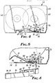
- the U-Matic cassette 52 differs from the VHS cassette 2 in that a second contact end 72 is required to bias the tape 54 outwardly toward its associated VTR in addition to a first contact end 74 which operates as described above to frictionally engage the tape 54 and press the tape 54 against a support 76.
- two contact ends 72 and 74 are provided by molding a receptacle 78 which includes two walls 80 and 82 which are separated to provide two openings 84 and 86 which accommodate opposite extensions of a slack limiter 88 formed as illustrated in FIGURE 6.
- the slack limiter 88 is comprised of a first tab portion 90 and a second tab portion 92, both of which terminate in contact ends 72 and 74 around which are wrapped polytetrafluoroethylene sheets 94 and 96.
- a mounting portion which includes two folds 100 and 102 formed in the body of the slack limiter 88 which are interconnected by a compression member 104 which forms acute angles with the tab portions 90 and 92.
- the slack limiter 88 is inserted in the receptacle 78 between corners 106 and 108 formed by the walls 80 and 82.
- the mounting of the slack limiter 88 of FIGURE 5 is double ended, the mounting
- portion 98 operates as described with respect to the slack limiter 24 of FIGURE 3 to retain and accurately position the slack limiter 88 within the receptacle 78.
- Excessive bowing of the compression member 104 allows easy insertion of the slack limiter 88 into the receptacle 78 and the resiliency of the compression member 104 causes the folds 100 and 102 to self-seat within the corners 106 and 108 an( allows a large difference between the length of the compression member 104 and the distance between the corners 106 and 108 to be absorbed.
- the slack limiter 88 of FIGURE 6 retains the advantages described above with respect to the slack limiter 24 of FIGURE 3 and additionally biases the tape 54 outwardly away from the cassette 52.
- the present invention has been describer with respect to certain specific embodiments, it will be apparent to those skilled in the art that modifications to the described embodiments are possible.
- the receptacles need not be rectangular in shape so long as corners are provided to contain and engage the compression members. It is intended that the invention include all modifications falling within the scope of the appended claims.
Abstract
Description
- This invention relates generally to cassettes of the type including a length of magnetic tape wound around at least one reel rotatably mounted in a housing with a portion of the tape extending to the exterior of the cassette for engagement by a recording and/or reproducing device and, in particular, a slack limiter for frictionally engaging the tape and limiting looseness or slack in the portion of the tape extending exteriorly of the cassette.
- While the subject matter of the invention has general utility with respect to one-quarter inch audio magnetic tape cassettes, one-half inch videotape of either the VHS or Beta formats, and three-quarter inch videotape cassettes, for simplicity the invention will be described with respect to one-half and three-quarter inch magnetic videotape cassettes which include two reels mounted within a housing with a length of magnetic tape wound around the two reels and extending between the reels.
- Slack or looseness in the length of tape between the reels in such a cassette can arise when the cassette is being transported or is otherwise separated from its associated recording and/or reproducing device, which device is commonly referred to as a videotape recorder (VTR). While some cassettes have locks which restrict rotation of the reels when the cassette is not in the VTR, it is still possible that one or both of the reels within the cassette housing may turn to unwind the tape and develop slack in the portion of the tape extending between the reels. Slack in the tape can also occur when the tape is engaged with the VTR. Typically, the VTR has spindles which engage the two reels. If driving and braking of the reels during the operation of the VTR is not synchronous, slack in the tape will develop. This slack may cause the tape to jam within the cassette housing or within the VTR and may lead to defective recording or reproducing operations.
- So-called slack limiters for avoiding such slac-): or looseness of the magnetic tape have been disclosed in U.S. Patents No. 3,797,779; 4,290,567; and 4,342,436 in which the slack limiters described commonly include a resilient, flexible strip, usually of plastic, affixed at one end to the cassette housing and having a free end coated with a layer of low friction material such as polytetrafluoroethylene (Teflon). The free end of the slack limiter presses the magnetic tape against a stationary portion of the cassette housing and thus frictionally prevents the magnetic tape from unwinding from the reel and developing slack. In addition, as described in U.S. Patent No. 4,342,436, the slack limiter may be double-ended, in which case a second free end of the slack limiter biases the magnetic tape outwardly from the cassette housing while the first free end performs the function described above.
- The foregoing patents are distinguished by the manner in which the slack limiter is attached to the cassette housing. In U.S. Patent No. 3,797,779, the slack limiter is affixed to the cassette housing with an adhesive. This method of attachment is relatively inefficient since the adhesive may deteriorate with age and eventually give way, allowing the slack limiter to fall from or within the cassette housing. Further, manufacturing costs are high because a number of steps are required for assembly and it is very difficult to automatically mount a slack limiter which is retained adhesively.
- Alternatively, U.S. Patents Nos. 4,290,567 and 4,342,436 disclose methods for mechanically attaching the slack limiter to the cassette housing in which a notch or slot formed in the slack limiter is engaged by a projection located within a receptacle formed in the housing. These methods have proven effective in retaining the slack limiter within the cassette housing, but a tolerance must be provided between the notch or slot and the housing projection, so movement of the slack limiter with respect to the cassette housing and the magnetic tape is likely. This movement of the slack limiter may result in less than full contact between the slack limiter and the magnetic tape, detrimental contact between a sharp edge of the slack limiter and the tape, or mistracking of the tape through the cassette.
- With respect to the slack limiter itself, it is a continuing goal to reduce manufacturing costs by reducing the number of operations which must be performed to produce the slack limiter and reducing the precision with which the slack limiter must be constructed without sacrificing precise positioning of the slack limiter within the cassette housing.
- The present invention provides an improved cassette having a slack limiter which is economically manufactured, which can be rapidly installed and properly positioned within a receptacle formed in the cassette, and which will absorb any tolerances between the receptacle and the slack limiter after installation.
- According to a first embodiment of the present invention, there is provided a flexible, resilient slack limiter including a tab portion terminating in a contact end coated with a low friction material adapted to frictionally engage a magnetic tape in a cassette of the type described above, and a mounting portion opposite the contact end which includes a fold and a compression member extending from the fold at an acute angle to the tab. The cassette housing includes a receptacle which compressively engages the compression member of the slack limiter and causes the compression member to bend or bow. The resiliency of the bowed compression member absorbs any tolerances between the compression member and the receptacle and accurately locates and positively retains the compression member with respect to the receptacle.
- According to a second embodiment of the present invention, there is provided a flexible, resilient slack limiter having two tab portions terminating in contact ends coated with a low friction material adapted to frictionally engage and bias the tape in a direction perpendicular to the extension of the tabs, and a mounting portion between the contact ends which includes two folds and an interconnecting compression member forming acute angles with the tabs. Opposite corners of a receptacle formed within the cassette housing engage the folds and cause the compression member to bend between the folds and resiliently bias the mounting portion of the slack limiter into position with respect to the housing receptacle.
- The present invention will be more thoroughly described with reference to the accompanying drawings wherein like numbers refer to like parts in the several views, and wherein:
- FIGURE 1 is a plan view of a cassette having parts broken away to show details and a first embodiment of a slack limiter and mounting receptacle according to the present invention;
- FIGURE 2 is an enlarged plan view of the lower, right-hand portion of the cassette of FIGURE 1;
- FIGURE 3 is a perspective view of the slack limiter used in the cassette of FIGURE 1;
- FIGURE 4 is a plan view of a cassette having portions broken away to show details and a second embodiment of a slack limiter according to the present invention;
- FIGURE 5 is an enlarged plan view of the lower, right-hand portion of the cassette of FIGURE 4; and
- FIGURE 6 is a perspective view of the slack limiter used in the cassette of FIGURE 4.
- Referring to FIGURE 1 of the drawings, there is illustrated a cassette 2 which comprises a
housing 4 including a lower moldedside wall assembly 6 and a mating upper moldedside wall assembly 8, tworeels side wall assemblies tape 14 having opposite end portions wound around thereels side wall assemblies tape access area 16 along the outer surface of thehousing 4 which is covered by adoor 18 when the cassette 2 is not in use. Thedoor 18 is pivoted open by a videotape recording machine (VTR) in which the cassette 2 is mounted to afford access to thetape 14 extending across theaccess area 16. Guide means including twocylindrical guide pins tape 14 between thereels access area 16. - As best seen in FIGURE 2, a
slack limiter 24 is mounted within a moldedreceptacle 26 formed in the lowerside wall assembly 6 with acontact end portion 28 of theslack limiter 24 biased to transversely, frictionally engage thetape 14 and press thetape 14 against a support surface provided by theguide pin 20 to resist unwinding of thetape 14 from thereel 10 and thus limit looseness or slack in thetape 14 extending between thereels - Referring to FIGURE 3, the
slack limiter 24 includes a thin,elongated tab portion 30 of a flexible, resilient polymeric material, which may be 0.10 mm thick polyester, having asheet 32 of polymeric material, which may be 0.09 mm thick polytetrafluoroethylene wrapped and adhered around one end to define thecontact end portion 28, and an opposite end defining amounting portion 34. Themounting portion 34 includes acompression member 36 and asharp fold 38 which is formed by bending and creasing the material comprising theslack limiter 24. Thecompression member 36 is thus an extension of thetab 30 - and is oriented at an acute angle with respect to the
tab portion 30. - Referring back to FIGURE 2, the
receptacle 26 includes abottom surface 40 which is a part of the majorflat surface 42 of the lowerside wall assembly 6 and awall 44 which extends perpendicularly from thebottom surface 40 to form a generally rectangular enclosure. Thereceptacle wall 44 includes anopening 46 through which thetab portion 30 of theslack limiter 24 extends. Thereceptacle 26 includes oppositeinterior corners compression member 36 and thus cause thecompression member 36 to be bent or bowed between thecorners compression member 36 forces thefold 38 into positive engagement with thecorner 48 and absorbs any tolerance between the length of thecompression member 36 and the distance between thecorners compression member 36 and the resiliency of the material also serves to absorb any plastic creep which may occur as theslack limiter 24 ages. - The length of the
compression member 36 may vary over a large range and still operate to force thefold 38 into thecorner 48, and so the total length of the material used to form theslack limiter 24 need not be calculated or cut with precision during manufacture. It is only required that thefold 38 be located precisely with respect to thecontact end 28 to ensure that thecontact end 28 is properly located. Accurate positioning of thefold 38 is easily accomplished during production and so theslack limiter 24 can be economically produced. - Insertion of the
slack limiter 24 into thereceptacle 26 can be easily and economically achieved by automated means because thecompression member 36 can be bowed more than is necessary to engage thecorners compression member 36 and thereceptacle 26. After insertion, thecompression member 36 will resiliently expand to contact thecorners receptacle 26 and will absorb the tolerance provided during assembly by excessively bowing thecompression member 36. - The cassette 2 described above and illustrated in FIGURE 1 is of the so-called VHS format in which a one-
half inch tape 14 is employed. FIGURE 4 illustrates acassette 52 which is commonly referred to as a U-Matic format cassette which utilizes a three-quarterinch width tape 54. Construction of thecassette 52 is similar to that of the cassette 2 of FIGURE 1 with the U-Maticcassette 52 including a lowerside wall assembly 56, an upper side wall assembly 58, tworeels tape 54 is wound, andguide pins tape 54 across anaccess area 70. However, the U-Maticcassette 52 differs from the VHS cassette 2 in that asecond contact end 72 is required to bias thetape 54 outwardly toward its associated VTR in addition to afirst contact end 74 which operates as described above to frictionally engage thetape 54 and press thetape 54 against asupport 76. - As shown in FIGURE 5, two
contact ends receptacle 78 which includes twowalls 80 and 82 which are separated to provide twoopenings slack limiter 88 formed as illustrated in FIGURE 6. Theslack limiter 88 is comprised of afirst tab portion 90 and asecond tab portion 92, both of which terminate incontact ends polytetrafluoroethylene sheets contact ends folds slack limiter 88 which are interconnected by acompression member 104 which forms acute angles with thetab portions - Referring again to FIGURE 5, the
slack limiter 88 is inserted in thereceptacle 78 betweencorners 106 and 108 formed by thewalls 80 and 82. Thus, although theslack limiter 88 of FIGURE 5 is double ended, the mounting -
portion 98 operates as described with respect to theslack limiter 24 of FIGURE 3 to retain and accurately position theslack limiter 88 within thereceptacle 78. Excessive bowing of thecompression member 104 allows easy insertion of theslack limiter 88 into thereceptacle 78 and the resiliency of thecompression member 104 causes thefolds corners 106 and 108 an( allows a large difference between the length of thecompression member 104 and the distance between thecorners 106 and 108 to be absorbed. Thus, even though theslack limiter 88 of FIGURE 6 is double ended rather than single ended, theslack limiter 88 retains the advantages described above with respect to theslack limiter 24 of FIGURE 3 and additionally biases thetape 54 outwardly away from thecassette 52. - Although the present invention has been describer with respect to certain specific embodiments, it will be apparent to those skilled in the art that modifications to the described embodiments are possible. For example, the receptacles need not be rectangular in shape so long as corners are provided to contain and engage the compression members. It is intended that the invention include all modifications falling within the scope of the appended claims.
Claims (8)
Applications Claiming Priority (2)
| Application Number | Priority Date | Filing Date | Title |
|---|---|---|---|
| US520606 | 1983-08-05 | ||
| US06/520,606 US4518135A (en) | 1983-08-05 | 1983-08-05 | Slack limiter for a magnetic tape cassette |
Publications (3)
| Publication Number | Publication Date |
|---|---|
| EP0133370A2 true EP0133370A2 (en) | 1985-02-20 |
| EP0133370A3 EP0133370A3 (en) | 1986-08-13 |
| EP0133370B1 EP0133370B1 (en) | 1989-10-11 |
Family
ID=24073330
Family Applications (1)
| Application Number | Title | Priority Date | Filing Date |
|---|---|---|---|
| EP84305254A Expired EP0133370B1 (en) | 1983-08-05 | 1984-08-02 | Slack limiter for a magnetic tape cassette |
Country Status (8)
| Country | Link |
|---|---|
| US (1) | US4518135A (en) |
| EP (1) | EP0133370B1 (en) |
| JP (1) | JPS6043282A (en) |
| KR (1) | KR920008991B1 (en) |
| BR (1) | BR8403755A (en) |
| CA (1) | CA1226670A (en) |
| DE (1) | DE3480133D1 (en) |
| HK (1) | HK38790A (en) |
Cited By (2)
| Publication number | Priority date | Publication date | Assignee | Title |
|---|---|---|---|---|
| DE3518963A1 (en) * | 1985-05-25 | 1986-11-27 | Agfa-Gevaert Ag, 5090 Leverkusen | Tape cassette with insertable tape wiper |
| EP0554788A2 (en) * | 1992-02-07 | 1993-08-11 | Matsushita Electric Industrial Co., Ltd. | Tape cassette |
Families Citing this family (9)
| Publication number | Priority date | Publication date | Assignee | Title |
|---|---|---|---|---|
| US4642722A (en) * | 1984-02-07 | 1987-02-10 | Minnesota Mining And Manufacturing Company | Spring mechanism for lid of video cassette |
| JPH0782735B2 (en) * | 1985-09-18 | 1995-09-06 | 日立マクセル株式会社 | Tape car ledge |
| FR2614704B1 (en) * | 1987-04-28 | 1989-07-28 | Aaton Sa | CINEMATOGRAPHIC CAMERA USING INTERCHANGEABLE FILM STORES WITH MOVEMENT OF THE AXLES OF THE RELEASE AND RECEIVING FILM REELS |
| JPH0524491Y2 (en) * | 1987-04-30 | 1993-06-22 | ||
| US4813628A (en) * | 1987-06-01 | 1989-03-21 | Minnesota Mining And Manufacturing Company | Slack limiter for a magnetic tape cassette |
| KR910008052B1 (en) * | 1989-08-18 | 1991-10-07 | 주식회사 에스케이씨 | Flap of video tape cassette |
| US5188310A (en) * | 1991-03-01 | 1993-02-23 | Athana Incorporated | Unidirectional tape tension element and method of use thereof |
| GB2257418B (en) * | 1991-07-09 | 1995-03-01 | Minnesota Mining & Mfg | A video cassette incorporating a slack limiter post |
| US20170323240A1 (en) | 2016-05-06 | 2017-11-09 | General Electric Company | Computing system to control the use of physical state attainment with inspection |
Citations (5)
| Publication number | Priority date | Publication date | Assignee | Title |
|---|---|---|---|---|
| GB2027676A (en) * | 1978-07-29 | 1980-02-27 | Tdk Electronics Co Ltd | Tape cassette |
| GB2057395A (en) * | 1979-06-29 | 1981-04-01 | Sony Corp | Magnetic tape cassettes |
| DE3142831A1 (en) * | 1980-10-31 | 1982-06-16 | Hitachi Maxell, Ltd., Ibaraki, Osaka | MAGNETIC TAPE CASSETTE |
| FR2534056A1 (en) * | 1982-09-13 | 1984-04-06 | Shape Inc | PRESSURE TONGUE ASSEMBLY FOR TAPE CASSETTE |
| EP0128271A1 (en) * | 1983-04-14 | 1984-12-19 | A.T.B. S.p.A. | Tape wiping brush |
Family Cites Families (7)
| Publication number | Priority date | Publication date | Assignee | Title |
|---|---|---|---|---|
| JPS5138749Y2 (en) * | 1971-07-14 | 1976-09-22 | ||
| JPS5756381Y2 (en) * | 1977-07-22 | 1982-12-04 | ||
| JPS56140978U (en) * | 1980-03-25 | 1981-10-24 | ||
| JPS5737336U (en) * | 1980-08-13 | 1982-02-27 | ||
| JPS5737950A (en) * | 1980-08-13 | 1982-03-02 | Fujitsu Ltd | Secret protection system |
| JPS57107179U (en) * | 1980-12-18 | 1982-07-01 | ||
| US4405097A (en) * | 1981-07-17 | 1983-09-20 | Minnesota Mining And Manufacturing Company | Cassette with a slack limiter tab |
-
1983
- 1983-08-05 US US06/520,606 patent/US4518135A/en not_active Expired - Lifetime
-
1984
- 1984-06-25 CA CA000457334A patent/CA1226670A/en not_active Expired
- 1984-07-12 JP JP59143410A patent/JPS6043282A/en active Pending
- 1984-07-27 BR BR8403755A patent/BR8403755A/en not_active IP Right Cessation
- 1984-08-02 EP EP84305254A patent/EP0133370B1/en not_active Expired
- 1984-08-02 DE DE8484305254T patent/DE3480133D1/en not_active Expired
- 1984-08-04 KR KR1019840004671A patent/KR920008991B1/en not_active IP Right Cessation
-
1990
- 1990-05-17 HK HK387/90A patent/HK38790A/en not_active IP Right Cessation
Patent Citations (5)
| Publication number | Priority date | Publication date | Assignee | Title |
|---|---|---|---|---|
| GB2027676A (en) * | 1978-07-29 | 1980-02-27 | Tdk Electronics Co Ltd | Tape cassette |
| GB2057395A (en) * | 1979-06-29 | 1981-04-01 | Sony Corp | Magnetic tape cassettes |
| DE3142831A1 (en) * | 1980-10-31 | 1982-06-16 | Hitachi Maxell, Ltd., Ibaraki, Osaka | MAGNETIC TAPE CASSETTE |
| FR2534056A1 (en) * | 1982-09-13 | 1984-04-06 | Shape Inc | PRESSURE TONGUE ASSEMBLY FOR TAPE CASSETTE |
| EP0128271A1 (en) * | 1983-04-14 | 1984-12-19 | A.T.B. S.p.A. | Tape wiping brush |
Cited By (3)
| Publication number | Priority date | Publication date | Assignee | Title |
|---|---|---|---|---|
| DE3518963A1 (en) * | 1985-05-25 | 1986-11-27 | Agfa-Gevaert Ag, 5090 Leverkusen | Tape cassette with insertable tape wiper |
| EP0554788A2 (en) * | 1992-02-07 | 1993-08-11 | Matsushita Electric Industrial Co., Ltd. | Tape cassette |
| EP0554788A3 (en) * | 1992-02-07 | 1994-10-26 | Matsushita Electric Ind Co Ltd | Tape cassette |
Also Published As
| Publication number | Publication date |
|---|---|
| US4518135A (en) | 1985-05-21 |
| EP0133370B1 (en) | 1989-10-11 |
| DE3480133D1 (en) | 1989-11-16 |
| CA1226670A (en) | 1987-09-08 |
| HK38790A (en) | 1990-05-25 |
| JPS6043282A (en) | 1985-03-07 |
| BR8403755A (en) | 1985-07-02 |
| KR920008991B1 (en) | 1992-10-12 |
| EP0133370A3 (en) | 1986-08-13 |
| KR850002157A (en) | 1985-05-06 |
Similar Documents
| Publication | Publication Date | Title |
|---|---|---|
| US4383660A (en) | Single reel tape cartridge with leader block door seal | |
| US4290567A (en) | Tape cassette brake assembly | |
| US4518135A (en) | Slack limiter for a magnetic tape cassette | |
| US4775115A (en) | Single reel tape cartridge used with a leader block | |
| US4342436A (en) | Tape cassette | |
| US4509087A (en) | Tape grounding element in a magnetic-tape cassette | |
| US4405097A (en) | Cassette with a slack limiter tab | |
| JPS6327341Y2 (en) | ||
| EP1150296A1 (en) | Magnetic tape cartridge | |
| JPS60261082A (en) | Press flap assembly for tape cassettee | |
| EP0086625B1 (en) | Tape cassette | |
| JPS61139987A (en) | Video cassette | |
| EP0096983B1 (en) | Tape cassette | |
| EP0096994B1 (en) | Tape cassette | |
| EP0404245A1 (en) | Magnetic-tape cassette | |
| US4130221A (en) | Torsion spring door for a videocassette | |
| US4813628A (en) | Slack limiter for a magnetic tape cassette | |
| US5177838A (en) | Fastener for magnetic tape cartridge and method of use thereof | |
| CA1150707A (en) | Endless type tape cassette | |
| JPS60182081A (en) | Video cassette | |
| JPH0516710Y2 (en) | ||
| JPH087585Y2 (en) | Tape cassette | |
| EP0530700A2 (en) | A cassette tape mount for use in a cassette tape recorder | |
| WO1995031810A1 (en) | Viedocassette housing with improved slack limiter area | |
| JPH0237191Y2 (en) |
Legal Events
| Date | Code | Title | Description |
|---|---|---|---|
| PUAI | Public reference made under article 153(3) epc to a published international application that has entered the european phase |
Free format text: ORIGINAL CODE: 0009012 |
|
| AK | Designated contracting states |
Designated state(s): DE FR GB IT |
|
| PUAL | Search report despatched |
Free format text: ORIGINAL CODE: 0009013 |
|
| AK | Designated contracting states |
Kind code of ref document: A3 Designated state(s): DE FR GB IT |
|
| 17P | Request for examination filed |
Effective date: 19870112 |
|
| 17Q | First examination report despatched |
Effective date: 19880315 |
|
| ITF | It: translation for a ep patent filed |
Owner name: BARZANO' E ZANARDO ROMA S.P.A. |
|
| GRAA | (expected) grant |
Free format text: ORIGINAL CODE: 0009210 |
|
| AK | Designated contracting states |
Kind code of ref document: B1 Designated state(s): DE FR GB IT |
|
| REF | Corresponds to: |
Ref document number: 3480133 Country of ref document: DE Date of ref document: 19891116 |
|
| ET | Fr: translation filed | ||
| PLBE | No opposition filed within time limit |
Free format text: ORIGINAL CODE: 0009261 |
|
| STAA | Information on the status of an ep patent application or granted ep patent |
Free format text: STATUS: NO OPPOSITION FILED WITHIN TIME LIMIT |
|
| 26N | No opposition filed | ||
| ITTA | It: last paid annual fee | ||
| REG | Reference to a national code |
Ref country code: GB Ref legal event code: IF02 |
|
| PGFP | Annual fee paid to national office [announced via postgrant information from national office to epo] |
Ref country code: FR Payment date: 20020717 Year of fee payment: 19 |
|
| PGFP | Annual fee paid to national office [announced via postgrant information from national office to epo] |
Ref country code: GB Payment date: 20020724 Year of fee payment: 19 |
|
| PGFP | Annual fee paid to national office [announced via postgrant information from national office to epo] |
Ref country code: DE Payment date: 20020830 Year of fee payment: 19 |
|
| PG25 | Lapsed in a contracting state [announced via postgrant information from national office to epo] |
Ref country code: GB Free format text: LAPSE BECAUSE OF NON-PAYMENT OF DUE FEES Effective date: 20030802 |
|
| PG25 | Lapsed in a contracting state [announced via postgrant information from national office to epo] |
Ref country code: DE Free format text: LAPSE BECAUSE OF NON-PAYMENT OF DUE FEES Effective date: 20040302 |
|
| GBPC | Gb: european patent ceased through non-payment of renewal fee |
Effective date: 20030802 |
|
| PG25 | Lapsed in a contracting state [announced via postgrant information from national office to epo] |
Ref country code: FR Free format text: LAPSE BECAUSE OF NON-PAYMENT OF DUE FEES Effective date: 20040430 |
|
| REG | Reference to a national code |
Ref country code: FR Ref legal event code: ST |