EP0132361A2 - Motorgeschwindigkeitsregelschaltung - Google Patents
Motorgeschwindigkeitsregelschaltung Download PDFInfo
- Publication number
- EP0132361A2 EP0132361A2 EP84304846A EP84304846A EP0132361A2 EP 0132361 A2 EP0132361 A2 EP 0132361A2 EP 84304846 A EP84304846 A EP 84304846A EP 84304846 A EP84304846 A EP 84304846A EP 0132361 A2 EP0132361 A2 EP 0132361A2
- Authority
- EP
- European Patent Office
- Prior art keywords
- winding
- circuit
- coupled
- current
- voltage
- Prior art date
- Legal status (The legal status is an assumption and is not a legal conclusion. Google has not performed a legal analysis and makes no representation as to the accuracy of the status listed.)
- Withdrawn
Links
Images


Classifications
-
- H—ELECTRICITY
- H02—GENERATION; CONVERSION OR DISTRIBUTION OF ELECTRIC POWER
- H02P—CONTROL OR REGULATION OF ELECTRIC MOTORS, ELECTRIC GENERATORS OR DYNAMO-ELECTRIC CONVERTERS; CONTROLLING TRANSFORMERS, REACTORS OR CHOKE COILS
- H02P25/00—Arrangements or methods for the control of AC motors characterised by the kind of AC motor or by structural details
- H02P25/02—Arrangements or methods for the control of AC motors characterised by the kind of AC motor or by structural details characterised by the kind of motor
- H02P25/022—Synchronous motors
- H02P25/024—Synchronous motors controlled by supply frequency
Definitions
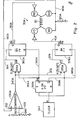
- the system of the invention 10 includes a hysteresis synchronous motor which drives apparatus (not shown) whose speed of rotation must be accurately controlled.
- the motor is not shown in detail but is represented by two windings 20 and 22, each of which has identical switching circuits 30A and 30B connected to it.
- the windings 20 and 22 are driven by signals generated by circuits 30A and 30B, which are 90° out of phase with each other.
- Corresponding elements of circuits 30A and 30B carry the same reference numeral, but those in circuit 30A carry the letter A and those in circuit 30B carry the letter B.
- Circuit 30A includes an input lead 40A coupled through an inverter 50A and a resistive path 60A to base 70A of a transistor 80A, which has its emitter 90A connected to the base 100A of a transistor 110A and its collector 112A connected to a bus 114A.
- the transistor 110A has its emitter 120Aconnected to a bus 130A and its collector 140A connected to the collector 150A of a transistor 160A whose emitter 170A is connected to a bus 180A.
- Circuit 30A also includes similar circuitry in which an input lead 190A is coupled through an inverter 200A and a resistive path 210A to the base 220A of a transistor 230A which has its emitter 240A connected to the base 250A of a transistor 260A and its collector 242A connected to a lead 244A to ground.
- the transistor 260A has its emitter 270A connected to bus 130A and its collector 280A connected to the collector 290A of a transistor 300A whose emitter 310A is connected to the bus 180A.
- Bus 130A is connected between the bases of transistors 80A and 230A, and bus 180A is connected between the emitters of transistors 160A and 300A.
- Collector 112A of transistor 80A is connected by bus 114A to the base of transistor 300A and to ground.
- Motor winding 20 is connected, as shown, between the connected collectors of transistors 110A and 160A and the connected collectors of transistors 260A and 300A .
- a plurality of current-sensing resistors 320A are connected in parallel between bus 180A and ground.
- One resistor of suitable value might also be used instead of several.
- bus or lead 180A is an output current-sensing lead and is connected to one input of a comparator 330A which has the second comparator voltage set within it by a voltage divider.
- the comparator has an output which is coupled by lead 340A to a switching circuit 350A having-outputs 0A and ⁇ A.
- Output 0A is connected to input lead 40A, and output ⁇ A is connected to input lead 190A.
- a master clock 344 which generates clock pulses, is coupled to the switching circuit 350A along with the output of the comparator 330A.
- a pulse ⁇ A (P3) on lead 190A causes transistors 160A and 260A to turn off, and the current wave W begins to fall from its peak value.
- This current flows from the 24 volt supply through these transistors 160A and 260A through the winding 20 in one direction to ground.
- the comparator 330A and switch circuit 350A operate to put a pulse OA (P2) on lead 40A which turns on transistors 110A and 300A.
- the associated circuit which drives the transistor-pairs operates as follows.
- a transistor-pair When a transistor-pair is turned on, a voltage is continually coupled on lead 180A to one input of the comparator circuit 330A.
- this voltage falls to the level at which the other input of the comparator is set by a voltage divider, an output pulse appears on line 340A from the comparator, and this is coupled to one input of the switching circuit 350A, the second input of which is coupled to the clock 344.
- the outputs from the switching circuit 350A are coupled to leads 40A and 190A, and the swtiching circuit produces a series of positive and negative pulses on these leads, with one series being 180° out of phase with the other and somewhat delayed to provide the required turn-off and turn-on described above.
- the comparator and switching circuits are shown in greater detail in Fig. 2.
- the comparator circuit 330A includes one input 332A, to which lead 180A is coupled, and a second input 333A which is set at a desired voltage by way of a voltage divider 184A and lead 182A.
- the switching circuit 350A has clock 344 coupled to a first toggle flip-flop 352A which has its Q output coupled by lead 354A to one input of a two low true AND gate 358A,the other input of which is coupled to lead 340A from the output of the comparator 330A.
- the Q output of the flip-flop 352A is also coupled by lead 355A to the reset (R) of a second set-reset flip-flop 360A.
- the output of the AND gate 358A is coupled by lead 364A to the set input (S) of the second flip-flop 360A.
- the Q output of the second flip-flop 360A is connected to lead 190A which runs to.the input of drive transistor 230A.
- the Q output of the first flip-flop 352A is connected by lead 368A to one input of a second (two low true) AND gate 370A, the second input of which is connected by lead 372A to lead 340A from the comparator 330A.
- the output of the second AND gate 370A is connected by lead 374A to the set input (S) of a third set-reset flip-flop 378A, and the reset (R) of the third flip-flop is connected by lead 380A to the Q output of the first flip-flop 352A.
- the Q output of the third flip-flop 378A is connected to lead 40A and to the input of transistor 110A.
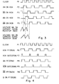
- the circuit shown in Fig. 2 operates as follows, with some of the pulses shown in Fig. 4.
- a positive pulse P6 is generated at the Q output of the flip-flop 352A and is applied to one input of the AND gate 358A and to the reset of flip-flop 360A.
- a negative pulse appears on the Q output, and this is applied to one of the inputs of the AND gate 370A and to the reset of the flip-flop 378A.
- the comparator 330A also couples pulses to the AND gates 358A and 370A, and these AND gates operate alternately with pulses P9 and P7, respectively, to energize the flip-flops 360A and 378A to generate the pulses P10 and P8, respectively, and to cause the pairs of transistors to turn on and to turn off, as described above.
- a string of clock pulses produces a string of positive and negative pulses P10 and P8 on leads 190A and 40A, with the pulses on line 40A being 180° out of phase with the pulses on line 190A.
- These pulses have a suitable relative delay caused by the time it takes for the voltage across resistors 320A to fall to the level at which the switching operation is produced.
- the comparator circuit includes one input from lead 180A which senses the voltage across the resistors 320A, the other input of which is set from the voltage divider 184A. An output pulse appears on line 340A from the comparator, and this is coupled to the second input of each of the AND gates 358A and 370A, and it is the appearance of these pulses which control the switching of the pairs of transistors.
- the circuit for driving motor winding 22 is identical to that described above except that the drive signals are 90° out of phase with the drive signals used in driving winding 20.
- the 90° phase shift is achieved by coupling the clock pulses from clock 344 through a lead and an inverter to the first flip-flop 352B of the circuit for driving winding 22.
Landscapes
- Engineering & Computer Science (AREA)
- Power Engineering (AREA)
- Control Of Motors That Do Not Use Commutators (AREA)
- Control Of Ac Motors In General (AREA)
Applications Claiming Priority (2)
| Application Number | Priority Date | Filing Date | Title |
|---|---|---|---|
| US51456783A | 1983-07-16 | 1983-07-16 | |
| US514567 | 1983-07-16 |
Publications (2)
| Publication Number | Publication Date |
|---|---|
| EP0132361A2 true EP0132361A2 (de) | 1985-01-30 |
| EP0132361A3 EP0132361A3 (de) | 1986-04-30 |
Family
ID=24047755
Family Applications (1)
| Application Number | Title | Priority Date | Filing Date |
|---|---|---|---|
| EP84304846A Withdrawn EP0132361A3 (de) | 1983-07-16 | 1984-07-16 | Motorgeschwindigkeitsregelschaltung |
Country Status (2)
| Country | Link |
|---|---|
| EP (1) | EP0132361A3 (de) |
| JP (1) | JPS6055894A (de) |
Citations (3)
| Publication number | Priority date | Publication date | Assignee | Title |
|---|---|---|---|---|
| DE2306607A1 (de) * | 1972-03-06 | 1973-09-20 | Ibm | Schaltungsanordnung zur ansteuerung einer induktiven last |
| US4306181A (en) * | 1979-08-17 | 1981-12-15 | Compumotion Corporation | Drive circuitry for electric motor |
| EP0059326A1 (de) * | 1981-02-26 | 1982-09-08 | International Business Machines Corporation | Steuerschaltung eines Schrittmotors zur synchronischen Umschaltung der Kernwicklung |
Family Cites Families (1)
| Publication number | Priority date | Publication date | Assignee | Title |
|---|---|---|---|---|
| JPS57153595A (en) * | 1981-03-17 | 1982-09-22 | Secoh Giken Inc | Constant-speed controlling circuit for ac motor |
-
1984
- 1984-07-12 JP JP59145882A patent/JPS6055894A/ja active Pending
- 1984-07-16 EP EP84304846A patent/EP0132361A3/de not_active Withdrawn
Patent Citations (3)
| Publication number | Priority date | Publication date | Assignee | Title |
|---|---|---|---|---|
| DE2306607A1 (de) * | 1972-03-06 | 1973-09-20 | Ibm | Schaltungsanordnung zur ansteuerung einer induktiven last |
| US4306181A (en) * | 1979-08-17 | 1981-12-15 | Compumotion Corporation | Drive circuitry for electric motor |
| EP0059326A1 (de) * | 1981-02-26 | 1982-09-08 | International Business Machines Corporation | Steuerschaltung eines Schrittmotors zur synchronischen Umschaltung der Kernwicklung |
Also Published As
| Publication number | Publication date |
|---|---|
| EP0132361A3 (de) | 1986-04-30 |
| JPS6055894A (ja) | 1985-04-01 |
Similar Documents
| Publication | Publication Date | Title |
|---|---|---|
| US5373436A (en) | Power converting device with inverter circuitry for driving multiple-phase variable-speed motor | |
| US3947738A (en) | Pulsed power supply | |
| US4167693A (en) | Control arrangement for a brushless D-C motor | |
| EP0627810B1 (de) | Abschaltbarer Halbbrücken-Austragszeit-Regler unter Verwendung eines einzelnen Kondensators | |
| EP0833439A1 (de) | Synchrones Antriebsverfahren für induktive Belastung und synchrone Steuereinrichtung für H-Brückenschaltung | |
| US4460282A (en) | Timepiece stepping motor drive circuit with stepping failure compensation | |
| US4584505A (en) | Torque-speed control system for asynchronous D.C. brushless motor | |
| EP0108732B1 (de) | Einrichtung zum Steuern eines Reluktanzmotors | |
| US4947283A (en) | Solenoid drive circuit | |
| US5247235A (en) | Method of supplying power to a single phase step motor | |
| US4159515A (en) | Inverter control system | |
| JPS5928158B2 (ja) | ステップ・モ−タの制動方法及び制動システム | |
| US4236196A (en) | Switching regulator | |
| US4081727A (en) | Speed control | |
| EP0613237B1 (de) | Zweirichtungs-Transkonduktanzverstärker mit Zerhacker | |
| US5166590A (en) | Method and circuit for feeding a single-phase stepping motor | |
| US4760320A (en) | Stepping-motor driving circuit | |
| GB2038043A (en) | Electronic timepiece | |
| EP0059326B1 (de) | Steuerschaltung eines Schrittmotors zur synchronischen Umschaltung der Kernwicklung | |
| EP0132361A2 (de) | Motorgeschwindigkeitsregelschaltung | |
| US5811953A (en) | Motor driving circuit and method | |
| KR910002794B1 (ko) | 전자기 구동회로 | |
| SU1541754A1 (ru) | Устройство дл управлени шаговым двигателем | |
| US6201716B1 (en) | Controller of power supplying apparatus with short circuit preventing means | |
| JP2933326B2 (ja) | ステッピングモータ駆動回路 |
Legal Events
| Date | Code | Title | Description |
|---|---|---|---|
| PUAI | Public reference made under article 153(3) epc to a published international application that has entered the european phase |
Free format text: ORIGINAL CODE: 0009012 |
|
| 17P | Request for examination filed |
Effective date: 19840723 |
|
| AK | Designated contracting states |
Designated state(s): BE DE FR GB IT NL SE |
|
| PUAL | Search report despatched |
Free format text: ORIGINAL CODE: 0009013 |
|
| AK | Designated contracting states |
Kind code of ref document: A3 Designated state(s): BE DE FR GB IT NL SE |
|
| RAP1 | Party data changed (applicant data changed or rights of an application transferred) |
Owner name: UNISYS CORPORATION |
|
| 17Q | First examination report despatched |
Effective date: 19870918 |
|
| STAA | Information on the status of an ep patent application or granted ep patent |
Free format text: STATUS: THE APPLICATION IS DEEMED TO BE WITHDRAWN |
|
| 18D | Application deemed to be withdrawn |
Effective date: 19880129 |
|
| RIN1 | Information on inventor provided before grant (corrected) |
Inventor name: KOSS, WILLIAM JUNIOR Inventor name: GEIS, TIMOTHY R. |