EP0132218A2 - Apparatus for coating steel tubes - Google Patents
Apparatus for coating steel tubes Download PDFInfo
- Publication number
- EP0132218A2 EP0132218A2 EP84730046A EP84730046A EP0132218A2 EP 0132218 A2 EP0132218 A2 EP 0132218A2 EP 84730046 A EP84730046 A EP 84730046A EP 84730046 A EP84730046 A EP 84730046A EP 0132218 A2 EP0132218 A2 EP 0132218A2
- Authority
- EP
- European Patent Office
- Prior art keywords
- foam body
- extruder head
- housing
- slot nozzle
- pipe
- Prior art date
- Legal status (The legal status is an assumption and is not a legal conclusion. Google has not performed a legal analysis and makes no representation as to the accuracy of the status listed.)
- Withdrawn
Links
Images

Classifications
-
- B—PERFORMING OPERATIONS; TRANSPORTING
- B29—WORKING OF PLASTICS; WORKING OF SUBSTANCES IN A PLASTIC STATE IN GENERAL
- B29C—SHAPING OR JOINING OF PLASTICS; SHAPING OF MATERIAL IN A PLASTIC STATE, NOT OTHERWISE PROVIDED FOR; AFTER-TREATMENT OF THE SHAPED PRODUCTS, e.g. REPAIRING
- B29C35/00—Heating, cooling or curing, e.g. crosslinking or vulcanising; Apparatus therefor
- B29C35/16—Cooling
-
- B—PERFORMING OPERATIONS; TRANSPORTING
- B29—WORKING OF PLASTICS; WORKING OF SUBSTANCES IN A PLASTIC STATE IN GENERAL
- B29C—SHAPING OR JOINING OF PLASTICS; SHAPING OF MATERIAL IN A PLASTIC STATE, NOT OTHERWISE PROVIDED FOR; AFTER-TREATMENT OF THE SHAPED PRODUCTS, e.g. REPAIRING
- B29C48/00—Extrusion moulding, i.e. expressing the moulding material through a die or nozzle which imparts the desired form; Apparatus therefor
- B29C48/03—Extrusion moulding, i.e. expressing the moulding material through a die or nozzle which imparts the desired form; Apparatus therefor characterised by the shape of the extruded material at extrusion
- B29C48/09—Articles with cross-sections having partially or fully enclosed cavities, e.g. pipes or channels
-
- B—PERFORMING OPERATIONS; TRANSPORTING
- B29—WORKING OF PLASTICS; WORKING OF SUBSTANCES IN A PLASTIC STATE IN GENERAL
- B29C—SHAPING OR JOINING OF PLASTICS; SHAPING OF MATERIAL IN A PLASTIC STATE, NOT OTHERWISE PROVIDED FOR; AFTER-TREATMENT OF THE SHAPED PRODUCTS, e.g. REPAIRING
- B29C48/00—Extrusion moulding, i.e. expressing the moulding material through a die or nozzle which imparts the desired form; Apparatus therefor
- B29C48/15—Extrusion moulding, i.e. expressing the moulding material through a die or nozzle which imparts the desired form; Apparatus therefor incorporating preformed parts or layers, e.g. extrusion moulding around inserts
- B29C48/151—Coating hollow articles
-
- B—PERFORMING OPERATIONS; TRANSPORTING
- B29—WORKING OF PLASTICS; WORKING OF SUBSTANCES IN A PLASTIC STATE IN GENERAL
- B29C—SHAPING OR JOINING OF PLASTICS; SHAPING OF MATERIAL IN A PLASTIC STATE, NOT OTHERWISE PROVIDED FOR; AFTER-TREATMENT OF THE SHAPED PRODUCTS, e.g. REPAIRING
- B29C48/00—Extrusion moulding, i.e. expressing the moulding material through a die or nozzle which imparts the desired form; Apparatus therefor
- B29C48/25—Component parts, details or accessories; Auxiliary operations
- B29C48/88—Thermal treatment of the stream of extruded material, e.g. cooling
- B29C48/911—Cooling
- B29C48/9115—Cooling of hollow articles
-
- B—PERFORMING OPERATIONS; TRANSPORTING
- B29—WORKING OF PLASTICS; WORKING OF SUBSTANCES IN A PLASTIC STATE IN GENERAL
- B29C—SHAPING OR JOINING OF PLASTICS; SHAPING OF MATERIAL IN A PLASTIC STATE, NOT OTHERWISE PROVIDED FOR; AFTER-TREATMENT OF THE SHAPED PRODUCTS, e.g. REPAIRING
- B29C35/00—Heating, cooling or curing, e.g. crosslinking or vulcanising; Apparatus therefor
- B29C35/16—Cooling
- B29C2035/1616—Cooling using liquids
-
- B—PERFORMING OPERATIONS; TRANSPORTING
- B29—WORKING OF PLASTICS; WORKING OF SUBSTANCES IN A PLASTIC STATE IN GENERAL
- B29C—SHAPING OR JOINING OF PLASTICS; SHAPING OF MATERIAL IN A PLASTIC STATE, NOT OTHERWISE PROVIDED FOR; AFTER-TREATMENT OF THE SHAPED PRODUCTS, e.g. REPAIRING
- B29C48/00—Extrusion moulding, i.e. expressing the moulding material through a die or nozzle which imparts the desired form; Apparatus therefor
- B29C48/03—Extrusion moulding, i.e. expressing the moulding material through a die or nozzle which imparts the desired form; Apparatus therefor characterised by the shape of the extruded material at extrusion
- B29C48/07—Flat, e.g. panels
- B29C48/08—Flat, e.g. panels flexible, e.g. films
-
- B—PERFORMING OPERATIONS; TRANSPORTING
- B29—WORKING OF PLASTICS; WORKING OF SUBSTANCES IN A PLASTIC STATE IN GENERAL
- B29C—SHAPING OR JOINING OF PLASTICS; SHAPING OF MATERIAL IN A PLASTIC STATE, NOT OTHERWISE PROVIDED FOR; AFTER-TREATMENT OF THE SHAPED PRODUCTS, e.g. REPAIRING
- B29C48/00—Extrusion moulding, i.e. expressing the moulding material through a die or nozzle which imparts the desired form; Apparatus therefor
- B29C48/15—Extrusion moulding, i.e. expressing the moulding material through a die or nozzle which imparts the desired form; Apparatus therefor incorporating preformed parts or layers, e.g. extrusion moulding around inserts
- B29C48/154—Coating solid articles, i.e. non-hollow articles
-
- B—PERFORMING OPERATIONS; TRANSPORTING
- B29—WORKING OF PLASTICS; WORKING OF SUBSTANCES IN A PLASTIC STATE IN GENERAL
- B29L—INDEXING SCHEME ASSOCIATED WITH SUBCLASS B29C, RELATING TO PARTICULAR ARTICLES
- B29L2023/00—Tubular articles
- B29L2023/22—Tubes or pipes, i.e. rigid
Definitions
- the invention relates to a device for sheathing steel pipes with plastic according to the preamble of claim 1.
- thermoplastic layer it is known to coat steel pipes with a thermoplastic layer in that, when heated, they pass through the slot nozzle of an extruder head designed as a ring slot nozzle and are thereby covered with a film tube which is connected to the pipe surface by means of a pressure sensitive adhesive (for example DE-PS 22 22 911 or DE-OS 17 04 851)
- a pressure sensitive adhesive for example DE-PS 22 22 911 or DE-OS 17 04 851
- the plastic layer is connected to the pipe surface by gluing with a pressure sensitive adhesive.
- the permissible level of the negative pressure and thus the pressing effect of the external air pressure are limited by the low mechanical resistance of the warm thermoplastic film stretched between the extruder die and the pipe to be coated.
- Sealing the vacuum chamber with a sleeve made of soft, elastic material can lead to excessive wear of the sleeve on the pipe surface, which is blasted with steel gravel and therefore rough.
- cuff abrasion can affect the adhesion of the coating to the pipe.
- the use of metallic sealing elements can impair the blasted pipe surface.
- a common feature of these known methods is that the tubes are guided through a cooling section after the sheathing, so that the still warm plastic layer is cooled to room temperature as quickly as possible.
- the invention is based on DE-OS 17 29 309, which has a pressure device for the plastic sheathing between the extruder head and the cooling section.
- This device can be designed as a pressure jaw, but it is also proposed to generate the pressure on the plastic by means of water emerging from nozzles.
- the mechanical pressure device can damage the surface of the casing, while a spray effect occurs due to the pressurized water, which can cause the disadvantages mentioned above.
- the object of the invention is therefore to design the device mentioned at the outset in such a way that it is possible to press the plastic as well as to avoid splashing water on sensitive parts of the still fresh coating. This object is achieved according to the invention with the features specified in claim 1.
- the invention is based on the idea of encompassing the freshly coated steel tube with a mechanical seal which essentially consists of an annular, elastic, soft foam body with at least partially open pores. Through the pores of the foam body, a cooling liquid, e.g. Water. This results in a uniform effect of the coolant on the fresh casing; a cooling and lubricating film of liquid forms on the jacket.
- a mechanical seal which essentially consists of an annular, elastic, soft foam body with at least partially open pores.
- a cooling liquid e.g. Water
- the foam body of the mechanical seal in an annular sheet metal container to which the Supply lines for the coolant are connected.
- the ring opening of the foam body is advantageously funnel-shaped on the side provided for the tube inlet and not cylindrical as on the side provided for the tube outlet.
- the two housing halves can be partitioned off from one another in the parting plane by housing walls and connected to a separately controllable supply line for the coolant.
- regulating the amount of coolant in the supply lines it is possible, for example, to compensate for the different amounts of coolant on the lower and upper half of the surface of the coated steel pipe, which are otherwise caused by the different hydrostatic pressure (in the case of large pipes, the pressure difference can be up to about 2 m water pressure) will.
- the purpose of regulating the amount of coolant is also to design the foam body with a flow resistance that decreases from bottom to top.
- the flow resistance can be achieved, for example, by a different pore structure of the S c foam body vary in the vertical direction.
- it can also be influenced in that parts of the surface of the ring opening of the foam body are provided with a dense coating, for example made of silicone rubber.
- the mechanical seal for sealing an overpressure chamber which is used instead of the described vacuum chamber.
- the pressure chamber connects with its essentially cylindrical housing directly to the ring slot nozzle of the extruder head, so that the tube outlet side of the extruder head and the tube inlet side of the pressure cam seal are interconnected.
- the excess pressure introduced is sealed by the inner surface of the extruder head and the outer surface of the still soft thermoplastic tubular film, while the required sealing effect on the tube outlet side of the pressure chamber is achieved by a mechanical seal arranged there and tightly connected to the housing of the pressure chamber.
- thermoplastic hose is pressed onto the pipe in a manner similar to the action of a vacuum chamber, without the disadvantages of a vacuum sealing sleeve described having to be accepted.
- the load capacity of the warm thermoplastic tubular film which is stretched between the steel tube and the extrusion tool, limits the permissible pressure difference between the inner and outer surface of the tubular film in the same way as in the vacuum chamber.
- the advantage is that the elastic pressing of the foam body lubricated with the cooling liquid of the mechanical seal or the mechanical seals, insofar as further mechanical seals are arranged behind the pressure chamber for the formation of sealed-off cooling zones, the effect of the pressing of the jacket film on the steel tube is additionally increased.
- Fig. 1 shows schematically the use of the mechanical seal according to the invention in the steel tube casing according to the tube extrusion process.
- the preheated steel tube 10 is passed through the extruder head with a ring slot nozzle 1 and coated with the tubular plastic film 11 (e.g. polyethylene).
- the tubular plastic film 11 e.g. polyethylene
- the mechanical seal according to the invention consisting of the housing 4 and the foam body 3 located therein.
- the supply line for the cooling medium is not shown.
- the foam body 3 encompasses the coated steel tube 10 and lies tightly on the surface of the jacket film 11, forming a lubricating film due to the cooling liquid.
- the mechanical seal shields the part of the coated steel tube 10 lying between the mechanical seal and the extruder head 1 from the influence of splash water from the cooling section, which is not shown here, arranged behind the mechanical seal as seen in the production direction.
- Fig. 2 shows one of the Fi. 1 corresponding arrangement of the mechanical seal in a system for sheathing steel pipes according to the winding process.
- a flat wrapping film 11 is extruded from a slot die 2 of an extruder head.
- the associated extruder is again not shown.
- the steel tube 10 is guided helically past the slot die 2 of the extruder head and wrapped with the extruded film 11.
- the mechanical seal arranged behind the extruder head comprises the covered steel tube 10 in the same way as in the first example and in turn causes the downstream cooling section to be partitioned off, which is not shown in detail here.
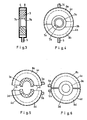
- FIG. 3 shows the structure of the mechanical seal in detail. It initially consists of e.g. made of sheet metal housing 4 with a cylindrical shell. The cover surfaces on both sides have corresponding circular openings for the passage of the jacketed steel pipes 10. A supply line 5 is provided on the outer surface of the housing 4 for the supply of the cooling liquid.
- the annular foam body 3 is arranged concentrically in the cylindrical housing 4.
- the foam body 3 also has an opening for the passage of the jacketed steel pipes 10 with a substantially cylindrical surface 7b.
- the surface 7a of the opening of the mechanical seal on the pipe entry side is advantageously formed in a funnel shape.
- a distribution space 8 for the cooling liquid is arranged on the inside of the housing 4 between the cylinder jacket and the outer surface of the foam body 3.
- the cooling liquid flowing in through the supply line 5 can thus surround the foam body 3 over its entire circumference.
- the foam body 3 has an open pore structure. Thus, the pressurized cooling liquid can flow through the foam body 3 and emerge on the surface 7a, 7b which rests on the coated steel tube 10.
- Fig. 4 shows a front view of a mechanical seal, which is carried out in a development of the invention with a split housing 4a, 4b.
- the lower housing half 4b is connected to the supply line 5, the upper housing half 4a to an outlet 14 for the coolant.
- the foam body 3a, 3b like the housing 4a, 4b, is divided into two halves and can be opened together with the housing 4a, 4b.
- the lower half of the foam body 3b is e.g. by a corresponding design of the pore structure or by applying a dense coating on parts of the surface 7a, 7b of the opening for the pipe leadthrough with a greater flow resistance for the cooling liquid than the upper half of the foam body 3a.
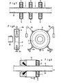
- the housing halves 4c, 4d are closed off by housing walls 6 in the parting plane except for a partial area which is filled by the foam body 3c, 3d.
- the distribution space 8a, 8b forms a self-contained space
- the distribution space for the cooling liquid is divided into two completely separate areas 8c, 8d.
- FIG. 7 shows three mechanical seals arranged axially one behind the other in a cooling section, by means of which cooling zones which are sealed off from one another are formed between the mechanical seals.
- Different cooling conditions can be realized through the individually adjustable amount of cooling liquid in each cooling zone, which is symbolized by the arrows pointing downwards.
- the mechanical seal is provided with an elastically movable suspension. In Fig. 8, this suspension is realized by two weighted cables 9a and two coil springs 9b.
- FIG. 9 A further advantageous embodiment of the invention is shown in FIG. 9; in this case the steel tube 10 is provided with the plastic casing 11 in an annular slot nozzle.
- a pressure chamber with an essentially cylindrical housing 12 is arranged behind the ring slot nozzle 1 of the extruder head and can be filled with compressed air through the feed line 13. While the pressure chamber 12, 13 on the side of the extruder head is sealed off by the extruded tubular film 11 and by the surface of the ring slot nozzle 1, the required seal on the tube outlet side of the pressure chamber is achieved by the mechanical seal according to the invention with the housing 4, the coolant supply 5 and the Foam body 3 realized.
Landscapes
- Engineering & Computer Science (AREA)
- Mechanical Engineering (AREA)
- Physics & Mathematics (AREA)
- Thermal Sciences (AREA)
- Health & Medical Sciences (AREA)
- Oral & Maxillofacial Surgery (AREA)
- Extrusion Moulding Of Plastics Or The Like (AREA)
Abstract
Die Erfindung betrifft eine Vorrichtung zum Ummanteln von Stahlrohren mltthermoplastischem Kunststoff, die einen Extruderkopf mit Schlitzdüse und in Transportrichtung der Rohre gesehen, hinter der Schlitzdüse eine Kühlstrecke aufweist. Um eine Vorrichtung für die Stahlrohrummantelung zu schaffen, bei der alle bisher bestehenden Mängel vermieden werden, wird vorgeschlagen, daß zwischen der Schlitzdüse (1, 2) und der Eintrittsseite der Kühlstrecke mindestens eine das ummantelte Rohr (10) eng umschließende Gleitringdichtung angeordnet ist, dessen Gleitring ein elastisch-weicher Schaumstoffkörper (3) mit offenen Poren ist, und die mit mindestens einer Zuleitung (5) für eine Kühlflüssigkeit versehen ist.
Description
Die Erfindung richtet sich auf eine Vorrichtung zur Ummantelung von Stahlrohren mit Kunststoff gemäß dem Oberbegriff des Anspruches 1.The invention relates to a device for sheathing steel pipes with plastic according to the preamble of
Es ist bekannt, Stahlrohre mit einer thermoplastischen Kunststoffschicht dadurch zu ummanteln, daß sie in erwärmten Zustand durch die als Ringschlitzdüse ausgebildete Schlitzdüse eines Extruderkopfes hindurchgeführt und dabei mit einem Folienschlauch überzogen werden, der mittels eines Haftklebers mit der Rohroberfläche verbunden wird (z.B. DE-PS 22 22 911 oder DE-OS 17 04 851) Für Rohre größerer Durchmesser ist es bekannt, die Ummantelung durch schraubenlinienförmiges Umwickeln mit einer streifenförmigen Thermoplast-Folie zu erzeugen, wobei die Rohre in Umdrehung versetzt und in Längsrichtung an einer als Breitschlitzdüse ausgebildete Schlitzdüse eines Extruderkopfes vorbeibewegt werden (z.B. DE-PS 17 71764 oder DE-PS 19 33 206). Auch in diesem Fall erfolgt die Verbindung der Kunststoffschicht mit der Rohroberfläche durch Verkleben mit einem Haftkleber.It is known to coat steel pipes with a thermoplastic layer in that, when heated, they pass through the slot nozzle of an extruder head designed as a ring slot nozzle and are thereby covered with a film tube which is connected to the pipe surface by means of a pressure sensitive adhesive (for example DE-PS 22 22 911 or DE-OS 17 04 851) For pipes of larger diameter, it is known to produce the sheathing by helical wrapping with a strip-shaped thermoplastic film, the pipes being rotated and moved in the longitudinal direction past a slot die designed as a slot die of an extruder head be (e.g. DE-PS 17 71764 or DE-PS 19 33 206). In this case too, the plastic layer is connected to the pipe surface by gluing with a pressure sensitive adhesive.
Mit der DE-PS 15 54 776 ist es für das Ummanteln mit einer Schlauchfolie bekanntgeworden, der Ringschlitzdüse eine Unterdruckkammer zuzuordnen, die an eine Vakuumpumpe angeschlossen ist, welche zwischen der Rohroberfläche und der aus der Ringschlitzdüse austretenden Schlauchfolie einen Unterdruck erzeugt. Damit wird der Zweck verfolgt, daß sich der Schlauch eng an das Rohr anlegt. Als Abdichtung gegen den innerhalb der Düse erzeugten Unterdruck dient eine Manschette, die an der Rohreintrittsseite des Extruderkopfes angeordnet ist und das unbeschichtete Rohr eng umschließt.With DE-PS 15 54 776 it has become known for sheathing with a tubular film, the ring slot nozzle to assign a vacuum chamber which is connected to a vacuum pump, which generates a vacuum between the pipe surface and the exiting from the ring slot nozzle. With that the Purpose is that the hose fits snugly against the pipe. A sleeve, which is arranged on the tube inlet side of the extruder head and closely encloses the uncoated tube, serves as a seal against the negative pressure generated inside the nozzle.
Die zulässige Höhe des Unterdruckes und damit die anpressende Wirkung des äußeren Luftdruckes sind dabei begrenzt durch die geringe mechanische Widerstandsfähigkeit der zwischen Extruderwerkzeug und dem zu beschichtenden Rohr aufgespannten warmen thermoplastischen Folie. Die Abdichtung der Unterdruckkammer durch eine Manschette aus weichem, elastischem Material kann zu starkem Verschleiß der Manschette auf der mit Stahlkies gestrahlten und damit rauhen Rohroberfläche führen. Außerdem kann der Abrieb der Manschette die Haftung der Beschichtung auf dem Rohr beeinträchtigen. Die Verwendung metallischer Dichtelemente kann umgekehrt die gestrahlte Rohroberfläche beeinträchtigen.The permissible level of the negative pressure and thus the pressing effect of the external air pressure are limited by the low mechanical resistance of the warm thermoplastic film stretched between the extruder die and the pipe to be coated. Sealing the vacuum chamber with a sleeve made of soft, elastic material can lead to excessive wear of the sleeve on the pipe surface, which is blasted with steel gravel and therefore rough. In addition, cuff abrasion can affect the adhesion of the coating to the pipe. Conversely, the use of metallic sealing elements can impair the blasted pipe surface.
Besondere Schwierigkeiten treten auf, wenn Rohre beschichtet werden sollen, die in einem unmittelbar vorausgehenden Arbeitsschritt mit einem Primer (z.B. Epoxiharz) versehen werden, der bei der Verarbeitungstemperatur noch viskos oder mechanisch leicht verletzbar ist.Particular difficulties arise when pipes are to be coated, which are provided with a primer (e.g. epoxy resin) in an immediately preceding work step, which is still viscous or mechanically vulnerable at the processing temperature.
Diesen bekannten Verfahren ist gemeinsam, daß die Rohre im Anschluß an die Ummantelung durch eine Kühlstrecke geführt werden, damit die noch warme Kunststoffschicht möglichst schnell auf Raumtemperatur abgekühlt wird. Hierfür ist es bekannt, auf den beschichteten Rohren einen Wasserfilm durch Berieseln mit Kühlwasser geringen Druckes zu bilden. Hierbei kann der Fall eintreten, daß Spritzwasser auf die noch weiche Thermoplastschicht auftrifft, wenn das frisch ummantelte Rohr die Beschichtungsstation (Ringschlitzdüse oder Breitschlitzdüse) verläßt. Da diese Schicht noch sehr druckempfindlich ist, können üle Wassertropfen unerwünschte Narben hinterlassen, die auch nach der Abkühlung erhalten bleiben.A common feature of these known methods is that the tubes are guided through a cooling section after the sheathing, so that the still warm plastic layer is cooled to room temperature as quickly as possible. For this purpose, it is known to form a water film on the coated pipes by sprinkling them with cooling water of low pressure. This can result in splash water hitting the still soft thermoplastic layer when the freshly jacketed tube leaves the coating station (ring slot nozzle or wide slot nozzle). Since this layer is still very sensitive to pressure, water droplets can leave unwanted scars that remain even after cooling.
Die Erfindung geht aus von der DE-OS 17 29 309, die eine Andruckvorrichtung für die Kunststoffummantelung zwischen Extruderkopf und Kühlstrecke aufweist. Diese Vorrichtung kann als Druckbacken ausgebildet sein, aber es wird auch vorgeschlagen, den Druck auf den Kunststoff durch aus Düsen austretendes Wasser zu erzeugen. Die mechanische Andruckvorrichtung kann zu Beschädigungen der Ummantelungsoberfläche führen, während durch das Druckwasser ein Sprüheffekt auftritt, der die vorstehend genannten Nachteile hervorrufen kann.The invention is based on DE-OS 17 29 309, which has a pressure device for the plastic sheathing between the extruder head and the cooling section. This device can be designed as a pressure jaw, but it is also proposed to generate the pressure on the plastic by means of water emerging from nozzles. The mechanical pressure device can damage the surface of the casing, while a spray effect occurs due to the pressurized water, which can cause the disadvantages mentioned above.
Aufgabe der Erfindung ist es daher, die eingangs genannte Vorrichtung so auszubilden, daß sowohl ein Andrücken des Kunststoffes möglich ist, wie auch das Auftreffen von Spritzwasser auf empfindliche Teile der noch frischen Beschichtung vermieden werden kann. Gelöst wird diese Aufgabe erfindungsgemäß mit den im Patentanspruch 1 angegebenen Merkmalen.The object of the invention is therefore to design the device mentioned at the outset in such a way that it is possible to press the plastic as well as to avoid splashing water on sensitive parts of the still fresh coating. This object is achieved according to the invention with the features specified in
Vorzugsweise Weiterbildungen ergeben sich aus den Unteransprüchen.Further developments preferably result from the subclaims.
Der Erfindung liegt der Gedanke zugrunde, das frischummantelte Stahlrohr mit einer Gleitringdichtung zu umfassen, die im wesentlichen aus einem ringförmigen elastisch-weichen Schaumstoffkörper mit mindestens teilweise offenen Poren besteht. Durch die Poren des Schaumstoffkröpers wird der Rohrummantelung eine Kühlflüssigkeit, z.B. Wasser, zugeführt. Dadurch wird eine gleichmäßige Einwirkung der Kühlflüssigkeit auf die frische Ummantelung erzielt; auf der Ummantelung bildet sich ein kühlender und gleichzeitig schmierender Flüssigkeitsfilm. Der Einsatz derartiger Gleitringdichtungen erlaubt es, beliebige Bereiche des beschichteten Stahlrohres wirksam gegen die Umgebung abzuschotten.The invention is based on the idea of encompassing the freshly coated steel tube with a mechanical seal which essentially consists of an annular, elastic, soft foam body with at least partially open pores. Through the pores of the foam body, a cooling liquid, e.g. Water. This results in a uniform effect of the coolant on the fresh casing; a cooling and lubricating film of liquid forms on the jacket. The use of such mechanical seals allows any areas of the coated steel pipe to be effectively sealed off from the environment.
In Weiterbildung der Erfindung wird vorgeschlagen, den Schaumstoffkörper der Gleitringdichtung in einem ringförmigen Blechbehälter anzuordnen, an den die Zuleitungen für die Kühlflüssigkeit angeschlossen sind. Um die Einfädelung eines Stahlrohres in die Gleitringdichtung zu erleichtern, wird die Ringöffnung des Schaumstoffkörpers an der für den Rohreintritt vorgesehenen Seite vorteilhaft trichterförmig und nicht wie an der für den Rohraustritt vorgesehenen Seite zylindrisch ausgebildet. Weiterhin ist es vorteilhaft, den Schaumstoffkörper der Gleitringdichtung aus mehreren Teilstücken zusammenzusetzen, die im Betriebszustand fest aneinandergedrückt sind. Es empfiehlt sich auch, den Schaumstoffkörper aus zwei Halbringen und den Blechbehälter entsprechend aus zwei aufklappbaren Hälften zusammenzusetzen. Darüberhinaus können die beiden Gehäusehälften in der Teilungsebene durch Gehäusewände gegeneinander abgeschottet und an je eine getrennt regelbare Zuleitung für die Kühlflüssigkeit angeschlossen sein. Durch Regelung der Mühlmittelmenge in den Zuleitungen kann z.B. ein Ausgleich für die sonst durch den unterschiedlichen hydrostatischen Druck (Bei Großrohren kann die Druckdifferenz bis zu etwa.2 m WS betragen.) bedingten unterschiedlichen Kühlmittelmengen auf der unteren und oberen Hälfte der Oberfläche des beschichteten Stahlrohres erzielt werden. Dem Zweck der Kühlflüssigkeitsmengenregelung dient es auch, den Schaumstoffkörper mit einem von unten nach oben hin abnehmenden Strömungswiderstand auszubilden. Der Strömungswiderstand läßt sich durch z.B. einen unterschiedlichen Porenaufbau des Schaumstoffkörpers in vertikaler Richtung variieren. Andererseits kann er auch dadurch beeinflußt werden, daß Teile der Oberfläche der Ringöffnung des Schaumstoffkörpers mit einer dichten Beschichtung, z.B. aus Silikon-Kautschuk, versehen werden.In a development of the invention it is proposed to arrange the foam body of the mechanical seal in an annular sheet metal container to which the Supply lines for the coolant are connected. In order to facilitate the threading of a steel tube into the mechanical seal, the ring opening of the foam body is advantageously funnel-shaped on the side provided for the tube inlet and not cylindrical as on the side provided for the tube outlet. Furthermore, it is advantageous to assemble the foam body of the mechanical seal from a plurality of sections which are firmly pressed together in the operating state. It is also advisable to assemble the foam body from two half rings and the sheet metal container from two foldable halves. In addition, the two housing halves can be partitioned off from one another in the parting plane by housing walls and connected to a separately controllable supply line for the coolant. By regulating the amount of coolant in the supply lines, it is possible, for example, to compensate for the different amounts of coolant on the lower and upper half of the surface of the coated steel pipe, which are otherwise caused by the different hydrostatic pressure (in the case of large pipes, the pressure difference can be up to about 2 m water pressure) will. The purpose of regulating the amount of coolant is also to design the foam body with a flow resistance that decreases from bottom to top. The flow resistance can be achieved, for example, by a different pore structure of the S c foam body vary in the vertical direction. On the other hand, it can also be influenced in that parts of the surface of the ring opening of the foam body are provided with a dense coating, for example made of silicone rubber.
Um die Wirksamkeit der Gleitringdichtung auch im Falle einer Verlagerung der Rohrachse, z.B. infolge von Schwingungen beim Transport der Stahlrohre, jederzeit zu gewährleisten, wird in Weiterbildung der Erfindung vorgeschlagen, die Gleitringdichtung an einer elastisch beweglichen Haltevorrichtung zu befestigen. Ferner ist es möglich, aufgrund des Abschottungseffektes der Gleitringdichtungen verschiedene Kühlzonen mit unterschiedlichen Kühlbedingungen aufzubauen, in dem mehrere Gleitringdichtungen im Abstand axial hintereinander entlang dem beschichteten Rohr angeordnet werden.To ensure the effectiveness of the mechanical seal even in the event of a displacement of the pipe axis, e.g. to ensure at all times as a result of vibrations during the transport of the steel pipes, it is proposed in a development of the invention to fasten the mechanical seal to an elastically movable holding device. Furthermore, it is possible to build up different cooling zones with different cooling conditions due to the partitioning effect of the mechanical seals, in which several mechanical seals are arranged axially one behind the other along the coated tube.
Schließlich wird in vorteilhafter Weiterbildung der Erfindung vorgeschlagen, die Gleitringdichtung zur Abdichtung einer überdruckkammer zu benutzen, die anstelle der beschriebenen Unterdruckkammer verwendet wird. Die Überdruckkammer schließt sich mit ihrem im wesentlichen zylinderförmigen Gehäuse unmittelbar an die Ringschlitzdüse des Extruderkopfes an, so daß die Rohraustrittsseite des Extruderkopfes und die Rohreintrittsseite der Überdruckkamer abgedichtet miteinander verbunden sind. An der Rohreintrittsseite der Überdruckkammer wird der eingeleitete Überdruck durch die Innenoberfläche des Extruderkopfes und die Außenoberfläche der noch weichen thermoplastischen Schlauchfolie abgedichtet, während die erforderliche Dichtwirkung auf der Rohraustrittsseite der Überdruckkammer durch eine dort angeordnete und mit dem Gehäuse der Überdruckkammer dicht verbundene Gleitringdichtung erzielt wird. Durch diese Anordnung wird erreicht, daß der Thermoplastschlauch in ähnlicher Weise wie durch die Wirkung einer Unterdruckkammer auf das Rohr aufgepreßt wird, ohne daß die beschriebenen Nachteile einer Unterdruckdichtmanschette in Kauf genommen werden müssen. Die Tragfähigkeit der warmen thermoplastischen Schlauchfolie, die zwischen dem Stahlrohr und dem Extrusionswerkzeug aufgespannt ist, begrenzt dabei in gleicher Weise wie bei der Unterdruckkammer die zulässige Druckdifferenz zwischen der inneren und äußeren Oberfläche der Schlauchfolie. Als Vorteil ergibt sich, daß durch die elastische Anpressung des mit der Kühlflüssigkeit geschmierten Schaumstoffkörpers der Gleitringdichtung bzw. der Gleitringdichtungen, soweit hinter der Überdruckkammer zur Bildung abgeschotteter Kühlzonen noch weitere Gleitringdichtungen angeordnet sind, der Effekt des Andrückens der Mantelfolie an das Stahlrohr zusätzlich verstärkt wird.Finally, in an advantageous development of the invention, it is proposed to use the mechanical seal for sealing an overpressure chamber which is used instead of the described vacuum chamber. The pressure chamber connects with its essentially cylindrical housing directly to the ring slot nozzle of the extruder head, so that the tube outlet side of the extruder head and the tube inlet side of the pressure cam seal are interconnected. At the tube inlet side of the pressure chamber, the excess pressure introduced is sealed by the inner surface of the extruder head and the outer surface of the still soft thermoplastic tubular film, while the required sealing effect on the tube outlet side of the pressure chamber is achieved by a mechanical seal arranged there and tightly connected to the housing of the pressure chamber. This arrangement ensures that the thermoplastic hose is pressed onto the pipe in a manner similar to the action of a vacuum chamber, without the disadvantages of a vacuum sealing sleeve described having to be accepted. The load capacity of the warm thermoplastic tubular film, which is stretched between the steel tube and the extrusion tool, limits the permissible pressure difference between the inner and outer surface of the tubular film in the same way as in the vacuum chamber. The advantage is that the elastic pressing of the foam body lubricated with the cooling liquid of the mechanical seal or the mechanical seals, insofar as further mechanical seals are arranged behind the pressure chamber for the formation of sealed-off cooling zones, the effect of the pressing of the jacket film on the steel tube is additionally increased.
Die Erfindung wird im folgenden anhand der in den Zeichnungen schematisch dargestellten Beispiele näher erläutert.The invention is explained below with reference to the examples shown schematically in the drawings.
Es zeigen:
- Fig. 1 Eine Gleitringdichtung in einer Schlauchummantelungsanlage,
- Fig. 2 eine Gleitringdichtung in einer Wickelummantelungsanlage,
- Fig. 3 einen Schnitt durch eine Gleitringdichtung,
- Fig. 4 eine Vorderansicht einer geteilten Gleitringdichtung,
- Fig. 5 eine Vorderansicht einer geteilten Gleitringdichtung im nichtmontierten Zustand,
- Fig. 6 eine Hinteransicht der Gleitringdichtung gemäß Abb. 5 im montierten Zustand,
- Fig. 7 eine Anordnung mehrerer Gleitringdichtungen zur Bildung abgeschotteter Kühlzonen,
- Fig. 8 eine elastisch aufgehängte Gleitringdichtung in Vorder- und Seitenansicht,
- Fig. 9 einen Schnitt durch einen Extruderkopf mit Ringschlitzdüse und angeschlossener Überdruckkammer.
- 1 a mechanical seal in a hose sheathing system,
- 2 shows a mechanical seal in a winding wrapping system,
- 3 shows a section through a mechanical seal,
- 4 is a front view of a split mechanical seal,
- 5 is a front view of a split mechanical seal in the unassembled state,
- 6 is a rear view of the mechanical seal according to Fig. 5 in the assembled state,
- 7 shows an arrangement of a plurality of mechanical seals to form partitioned cooling zones,
- 8 is an elastically suspended mechanical seal in front and side view,
- Fig. 9 shows a section through an extruder head with ring slot die and connected pressure chamber.
Gleichartige Teile sind in den Zeichnungen mit gleichen Bezugszeichen versehen.Similar parts are provided with the same reference symbols in the drawings.
Fig. 1 zeigt schematisch den Einsatz der erfindungsgemäßen Gleitringdichtung bei der Stahlrohrummantelung nach dem Schlauchextrusionsverfahren. Das vorgewärmte Stahlrohr 10 wird durch den Extruderkopf mit Ringschlitzdüse 1 hindurchgeführt und mit der schlauchförmigen Kunststoffolie 11 (z.B. Polyäthylen) ummantelt.Fig. 1 shows schematically the use of the mechanical seal according to the invention in the steel tube casing according to the tube extrusion process. The preheated
In Produktionsrichtung hinter dem Extruderkopf ist die erfindungsgemäße Gleitringdichtung bestehend aus dem Gehäuse 4 und dem darin befindlichen Schaumstoffkörper 3 angeordnet. Die Zuleitung für das Kühlmedium ist nicht dargestellt. Der Schaumstoffkörper 3 umfaßt das umhüllte Stahlrohr 10 und liegt dabei unter Bildung eines Schmierfilmes durch die Kühlflüssigkeit dicht auf der Oberfläche der Mantelfolie 11 auf. Somit schirmt die Gleitringdichtung den zwischen der Gleitringdichtung und dem Extruderkopf 1 liegenden Teil des ummantelten Stahlrohres 10 vor dem Einfluß von Spritzwasser aus der in Produktionsrichtung gesehen hinter der Gleitringdichtung angeordneten, hier nicht näher dargestellten Kühlstrecke ab.In the production direction, behind the extruder head, the mechanical seal according to the invention, consisting of the
Fig. 2 zeigt eine der Fi. 1 entsprechende Anordnung der Gleitringdichtung in einer Anlage zur Ummantelung von Stahlrohren nach dem Wickelverfahren. Hierbei wird eine flache Wickelfolie 11 aus einer Breitschlitzdüse 2 eines Extruderkopfes extrudiert. Der zugehörige Extruder ist wiederum nicht dargestellt. Das Stahlrohr 10 wird schraubenlinienförmig an der Breitschlitzdüse 2 des Extruderkopfes vorbeigeführt und mit der extrudierten Folie 11 umwickelt. Die hinter dem Extruderkopf angeordnete Gleitringdichtung umfaßt in gleicher Weise wie im ersten Beispiel das umhUllte Stahlrohr 10 und bewirkt wiederum eine Abschottung der nachgelagerten Kühlstrecke, die hier nicht im einzelnen dargestellt ist.Fig. 2 shows one of the Fi. 1 corresponding arrangement of the mechanical seal in a system for sheathing steel pipes according to the winding process. Here, a
Das Schnittbild in Fig. 3 zeigt den Aufbau der Gleitringdichtung im einzelnen. Sie bsteht zunächst aus einem z.B. aus Blech gefertigten Gehäuse 4 mit einem zylinderförmigen Mantel. Die beiderseitigen Deckflächen weisen für die Durchführung der ummantelten Stahlrohre 10 entsprechende kreisförmige Öffnungen auf. Für die Zufuhr der Kühlflüssigkeit ist an der Mantelfläche des Gehäuses 4 eine Zuleitung 5 vorgesehen.The sectional view in Fig. 3 shows the structure of the mechanical seal in detail. It initially consists of e.g. made of
Der ringförmige Schaumstoffkörper 3 ist konzentrisch in dem zylinderförmigen Gehäuse 4 angeordnet. Der Schaumstoffkörper 3 weist ebenfalls f+r die Durchführung der ummantelten Stahlrohre 10 eine Öffnung mit im wesentlichen zylinderförmiger Oberfläche 7b auf. Zur Erleichterung der Einfädelung der Stahlrohre 10 wird die Oberfläche 7a der Öffnung der Gleitringdichtung auf der Rohreintrittsseite vorteilhaft trichterförmig ausgebildet. Aus der Zeichnung ist weiterhin ersichtlich, daß auf der Innenseite des Gehäuses 4 zwischen dem Zylindermantel und der Außenoberfläche des Schaumstoffkörpers 3 ein Verteilraum 8 für die Kühlflüssigkeit angeordnet ist. Die durch die Zuleitung 5 einströmende Kühlflüssigkeit kann somit den Schaumstoffkörper 3 über seinen gesamten Umfang umgebea. Der Schaumstoffkörper 3 besitzt eine offene Porenstruktur. Somit kann die unter Druck stehende Kühlflüssigkeit durch den Schaumstoffkörper 3 hindurchströmen und an der Oberfläche 7a, 7b, die auf dem ummantelten Stahlrohr 10 aufliegt, austreten. Auf diese Weise wird auf der Oberfläche der Rohrummantelung 11 ein gleichmäßiger Kühlmittelfilm ausgebildet, der einen Schmiereffekt bewirkt und dadurch verhindert, daß der mit mechanischem Druck auf die Rohrummantelung 11 einwirkende Schaumstoffkörper 3 die Oberfläche der Rohrummantelung 11 beschädigt. Die Druckeinwirkung des Schaumstoffkörpers 3 unterstützt das erwünschte dichte Anlegen der Rohrummantelung 11 an die Oberfläche des Stahlrohres 10.The
Fig. 4 zeigt in Vorderansicht eine Gleitringdichtung, die in Weiterbildung der Erfindung mit einem geteilten Gehäuse 4a, 4b ausgeführt ist. Die untere Gehäusehälfte 4b ist an die Zuleitung 5, die obere Gehäusehälfte 4a an einen Ablauf 14 für die Kühlflüssigkeit angeschlossen. Der Schaumstoffkörper 3a, 3b ist wie das Gehäuse 4a, 4b in zwei Hälften aufgeteilt und zusammen mit dem Gehäuse 4a, 4b aufklappbar ausgeführt. In vorteilhafter Weiterbildung der Erfindung ist die untere Hälfte des Schaumstoffkörpers 3b z.B. durch eine entsprechende Gestaltung der Porenstruktur oder durch Aufbringen einer dichten Beschichtung auf Teilen der Oberfläche 7a, 7b der Öffnung für die Rohrdurchführung mit einem größeren Strömungswiderstand für die Kühlflüssigkeit ausgebildet als die obere Hälfte des Schaumstoffkörpers 3a.Fig. 4 shows a front view of a mechanical seal, which is carried out in a development of the invention with a
Dadurch wird ein Ausgleich für die sonst durch den unterschiedlichen hydrostatischen Druck bedingten unterschiedlichen Mengen der an der oberen bzw, unteren Hälfte der Rohrummantelung austretenden Kühlflüssigkeit und den damit verbundenen Kühleffekt erzielt. Da der Druckunterschied mit dem Durchmesser der zu beschichtenden Stahlrohre 10 zunimmt, ist die Ausführung mit unterschiedlichem Strömungswiderstand in den Teilen des Schaumstoffkörpers 3a, 3b besonders bei der Ummantelung von Großrohren empfehlenswert. Dieser Effekt läßt sich auch durch die in Fig. 5 und 6 in Vorder- und Hinteransicht einer Gleitringdichtung dargestellten konstruktiven Maßnahmen erreichen. Hierbei ist wiederum das Gehäuse 4c, 4d und der Schaumstoffkörper 3c, 3d in zwei getrennten Hälften ausgeführt. Beide Gehäusehälften 4c, 4d weisen jeweils eine getrennt regelbare Zuleitung 5a, 5b für das Kühlmedium auf. Im Gegensatz zu Fig. 4 sind die Gehäusehälften 4c, 4d in der Teilungsebene bis auf einen Teilbereich, der von dem Schaumstoffkörper 3c, 3d ausgefüllt ist, durch Gehäusewände 6 abgeschlossen. Dadurch ist der Verteilraum für die Kühlflüssigkeit im Gegensatz zu Fig. 4, wo der Verteilraum 8a, 8b einen in sich geschlossenen Raum bildet, in zwei voneinander völlig getrennte Bereiche 8c, 8d aufgeteilt. Durch Regelung der Kühlflüssigkeitszufuhr durch die Zuleitungen 5a, 5b können trotz gleicher Porenstruktur des Schaumstoffkörpers 3c, 3d in den beiden Hälften der Gleitringdichtung gleiche Mengen der austretenden Kühlflüssigkeit eingestellt werden.This compensates for the different amounts of the cooling liquid escaping from the upper or lower half of the tube casing, which are otherwise caused by the different hydrostatic pressure, and the associated cooling effect. Since the pressure difference increases with the diameter of the
Fig. 7 zeigt drei in einer Kühlstrecke axial hintereinander angeordnete Gleitringdichtungen, durch die gegeneinander abgeschottete Kühlzonen .zwischen den Gleitringdichtungen gebildet werden. Durch die in jeder Kühlzone individuell einstellbare Kühlflüssigkeitsmenge, die durch die eingezeichneten, nach unten gerichteten Pfeile symbolisiert ist, können unterschiedliche Abkühlungsbedingungen realisiert werden. Zur Vermeidung negativer Auswirkungen durch Verlagerung der Rohrachse, z.B. infolge von Schwingungen durch die Transporteinrichtungen der Rohrbeschichtungsanlage wird die Gleitringdichtung mit einer elastischbeweglichen Aufhängung versehen. In Fig. 8 ist diese Aufhängung durch zwei gewichtsbelastete Seilzüge 9a und zwei Schraubenfedern 9b realisiert.7 shows three mechanical seals arranged axially one behind the other in a cooling section, by means of which cooling zones which are sealed off from one another are formed between the mechanical seals. Different cooling conditions can be realized through the individually adjustable amount of cooling liquid in each cooling zone, which is symbolized by the arrows pointing downwards. In order to avoid negative effects due to displacement of the pipe axis, for example as a result of vibrations caused by the transport devices of the pipe coating system, the mechanical seal is provided with an elastically movable suspension. In Fig. 8, this suspension is realized by two
Eine weitere vorteilhafte Ausgestaltung der Erfindung zeigt Fig. 9; hierbei wird das Stahlrohr 10 in einer Ringschlitzdüse mit der Kunststoffummantelung 11 versehen. Zur Verbesserung eines dichten Anlegens des Kunststoffmantels 11 an die Oberfläche des Stahlrohres 10 ist hinter der Ringschlitzdüse 1 des Extruderkopfes eine Überdruckkammer mit einem im wesentlichen zyliderförmigen Gehäuse 12 angeordnet, das durch die Zuleitung 13 mit Druckluft gefüllt werden kann. Während die Uberdruckkammer 12, 13 auf der Seite des Extruderkopfes durch die extrudierte Schlauchfolie 11 und durch die Oberfläche der Ringschlitzdüse 1 dicht abgeschlossen ist, wird die erforderliche Abdichtung auf der Rohraustrittsseite der Überdruckkammer durch die erfindungsgemäße Gleitringdichtung mit dem Gehäuse 4, der Kühlmittelzufuhr 5 und dem Schaumstoffkörper 3 realisiert. Diese Anordnung gewährleistet, daß das Spritzwasser der nachfolgenden nicht dargestellten Kühlzone nicht in die frisch ummantelten Bereiche des Stahlrohres 10 eindringen kann und daß die Uberdruckkammer 12, l3 gut abgedichtet ist, ohne durch das erforderliche, die Oberfläche der Rohrummantelung 11 berührende Dichtelement Beschädigungen der Rohrummantelung 11 hervorzurufen. Im übrigen wird durch das mechanische Andrücken der Rohrummantelung 11 auf das Stahlrohr 10 durch den das Stahlrohr 10 umschliessenden Schaumstoffkörper 3 die dichte Anlage der Rohrummantelung 11 an das Stahlrohr 10 gefödert.A further advantageous embodiment of the invention is shown in FIG. 9; in this case the
Claims (9)
Applications Claiming Priority (2)
| Application Number | Priority Date | Filing Date | Title |
|---|---|---|---|
| DE3325439 | 1983-07-12 | ||
| DE3325439A DE3325439C1 (en) | 1983-07-12 | 1983-07-12 | Device for sheathing a steel pipe |
Publications (2)
| Publication Number | Publication Date |
|---|---|
| EP0132218A2 true EP0132218A2 (en) | 1985-01-23 |
| EP0132218A3 EP0132218A3 (en) | 1986-02-19 |
Family
ID=6203990
Family Applications (1)
| Application Number | Title | Priority Date | Filing Date |
|---|---|---|---|
| EP84730046A Withdrawn EP0132218A3 (en) | 1983-07-12 | 1984-05-02 | Apparatus for coating steel tubes |
Country Status (2)
| Country | Link |
|---|---|
| EP (1) | EP0132218A3 (en) |
| DE (1) | DE3325439C1 (en) |
Cited By (13)
| Publication number | Priority date | Publication date | Assignee | Title |
|---|---|---|---|---|
| WO1995019522A1 (en) * | 1994-01-13 | 1995-07-20 | Fulton-Rohr Gmbh & Co. Kg | Pipes for systems used in motor vehicles and process for producing the same |
| US5849382A (en) * | 1996-07-12 | 1998-12-15 | Itt Automotive Europe Gmbh | Tubing for systems in automotive vehicles and a method of manufacturing the same |
| WO2009127569A1 (en) * | 2008-04-16 | 2009-10-22 | Kraussmaffei Technologies Gmbh | Extrusion apparatus for the production of plastic pipes, seals therefor |
| US8734909B2 (en) | 2010-03-10 | 2014-05-27 | Eastman Chemical Company | Methods and apparatus for coating substrates |
| WO2014088924A1 (en) * | 2012-12-06 | 2014-06-12 | Eastman Chemical Company | Process and system for extrusion coating of elongated substrates |
| US9289795B2 (en) | 2008-07-01 | 2016-03-22 | Precision Coating Innovations, Llc | Pressurization coating systems, methods, and apparatuses |
| US9604251B2 (en) | 2008-07-16 | 2017-03-28 | Eastman Chemical Company | Thermoplastic formulations for enhanced paintability, toughness and melt processability |
| US9616457B2 (en) | 2012-04-30 | 2017-04-11 | Innovative Coatings, Inc. | Pressurization coating systems, methods, and apparatuses |
| US9744707B2 (en) | 2013-10-18 | 2017-08-29 | Eastman Chemical Company | Extrusion-coated structural members having extruded profile members |
| WO2017148462A1 (en) * | 2016-03-04 | 2017-09-08 | INOEX GmbH Innovationen und Ausrüstungen für die Extrusionstechnik | Seal device for a negative pressure calibrating unit in an extrusion line |
| US9920526B2 (en) | 2013-10-18 | 2018-03-20 | Eastman Chemical Company | Coated structural members having improved resistance to cracking |
| CN112223710A (en) * | 2020-08-27 | 2021-01-15 | 汪鹏 | Method for coating EPE on surface of metal pipe to extrude and foam |
| CN115366407A (en) * | 2022-09-05 | 2022-11-22 | 上海阶明软管有限公司 | Rubber tube film-coating forming device and process thereof |
Family Cites Families (3)
| Publication number | Priority date | Publication date | Assignee | Title |
|---|---|---|---|---|
| US3503823A (en) * | 1966-04-04 | 1970-03-31 | Polymer Corp | Method for coating metal substrates with thermoplastic resins |
| DE1704851A1 (en) * | 1967-09-08 | 1971-05-27 | Mannesmann Ag | Injection head for an extruder for the extrusion of hollow profiles made of thermoplastics |
| DE1933206C3 (en) * | 1969-06-26 | 1973-11-22 | Mannesmann Ag, 4000Duesseldorf | Device for continuous processing or testing of the surface of elongated workpieces, in particular for wrapping steel pipes with strips of thermoplastic material |
-
1983
- 1983-07-12 DE DE3325439A patent/DE3325439C1/en not_active Expired
-
1984
- 1984-05-02 EP EP84730046A patent/EP0132218A3/en not_active Withdrawn
Cited By (19)
| Publication number | Priority date | Publication date | Assignee | Title |
|---|---|---|---|---|
| WO1995019522A1 (en) * | 1994-01-13 | 1995-07-20 | Fulton-Rohr Gmbh & Co. Kg | Pipes for systems used in motor vehicles and process for producing the same |
| US5849382A (en) * | 1996-07-12 | 1998-12-15 | Itt Automotive Europe Gmbh | Tubing for systems in automotive vehicles and a method of manufacturing the same |
| WO2009127569A1 (en) * | 2008-04-16 | 2009-10-22 | Kraussmaffei Technologies Gmbh | Extrusion apparatus for the production of plastic pipes, seals therefor |
| CN102006982A (en) * | 2008-04-16 | 2011-04-06 | 克劳斯玛菲科技有限公司 | Extrusion apparatus for the production of plastic pipes, seals therefor |
| US9289795B2 (en) | 2008-07-01 | 2016-03-22 | Precision Coating Innovations, Llc | Pressurization coating systems, methods, and apparatuses |
| US10576491B2 (en) | 2008-07-01 | 2020-03-03 | Precision Coating Innovations, Llc | Pressurization coating systems, methods, and apparatuses |
| US9604251B2 (en) | 2008-07-16 | 2017-03-28 | Eastman Chemical Company | Thermoplastic formulations for enhanced paintability, toughness and melt processability |
| US8734909B2 (en) | 2010-03-10 | 2014-05-27 | Eastman Chemical Company | Methods and apparatus for coating substrates |
| US9616457B2 (en) | 2012-04-30 | 2017-04-11 | Innovative Coatings, Inc. | Pressurization coating systems, methods, and apparatuses |
| US8865261B2 (en) | 2012-12-06 | 2014-10-21 | Eastman Chemical Company | Extrusion coating of elongated substrates |
| US9919503B2 (en) | 2012-12-06 | 2018-03-20 | Eastman Chemical Company | Extrusion coating of elongated substrates |
| WO2014088924A1 (en) * | 2012-12-06 | 2014-06-12 | Eastman Chemical Company | Process and system for extrusion coating of elongated substrates |
| US9744707B2 (en) | 2013-10-18 | 2017-08-29 | Eastman Chemical Company | Extrusion-coated structural members having extruded profile members |
| US9920526B2 (en) | 2013-10-18 | 2018-03-20 | Eastman Chemical Company | Coated structural members having improved resistance to cracking |
| WO2017148462A1 (en) * | 2016-03-04 | 2017-09-08 | INOEX GmbH Innovationen und Ausrüstungen für die Extrusionstechnik | Seal device for a negative pressure calibrating unit in an extrusion line |
| CN109070423A (en) * | 2016-03-04 | 2018-12-21 | 因诺伊克斯压铸技术创新设备有限责任公司 | The sealing device of negative pressure calibration unit is used in extrusion line |
| US20190063611A1 (en) * | 2016-03-04 | 2019-02-28 | Inoex Gmbh Innovationen Und Ausruestungen Fuer Die Extrusionstechnik | Seal device for a negative pressure calibrating unit in an extrusion line |
| CN112223710A (en) * | 2020-08-27 | 2021-01-15 | 汪鹏 | Method for coating EPE on surface of metal pipe to extrude and foam |
| CN115366407A (en) * | 2022-09-05 | 2022-11-22 | 上海阶明软管有限公司 | Rubber tube film-coating forming device and process thereof |
Also Published As
| Publication number | Publication date |
|---|---|
| DE3325439C1 (en) | 1985-01-03 |
| EP0132218A3 (en) | 1986-02-19 |
Similar Documents
| Publication | Publication Date | Title |
|---|---|---|
| DE19912199B4 (en) | Method for producing a flexible tube for an endoscope | |
| DE69114042T2 (en) | Process for limiting the width of the coating when coating paper or cardboard and device for carrying out this process. | |
| EP0132218A2 (en) | Apparatus for coating steel tubes | |
| CH428189A (en) | Method and device for producing pipes | |
| EP1042110B1 (en) | Method and device for fiber impregnation | |
| DE19629796C5 (en) | Plastic composite insulator with a spiral shield and process for its production | |
| DE1435417A1 (en) | Device and method for the treatment of fiber material | |
| DE19545597A1 (en) | Shell for printing or screen roll | |
| DE4108489C2 (en) | Method and device for applying a uniform layer of adhesive to a resin-coated mandrel | |
| DE1779612A1 (en) | Method and device for the production of reinforced hoses | |
| DE2304515B2 (en) | Medium-tight closure device at the outlet end of a vulcanizing tube of an extruder for insulating electrical conductors | |
| DE4028198C2 (en) | ||
| DE3013891C2 (en) | Electrostatic powder spraying process to create a paint application | |
| DE2856827C3 (en) | Device for coating freely tensioned suspension ropes with deformable coating compounds | |
| EP1475159A1 (en) | Powder spray coating device | |
| DE9109334U1 (en) | Device for lining pipelines with an internal coating | |
| DE2847871C2 (en) | Cable for transmitting ultrasonic waves | |
| DE2926223A1 (en) | Conductive wire covering - with elastomer or plastomer by microwave energy in extruder head for vulcanisation or crosslinking | |
| DE3219569A1 (en) | Apparatus for continuous application of sprayable materials, particularly for coloring strand-like materials | |
| DE69720760T2 (en) | METHOD AND DEVICE FOR TRANSFERING ADDITIONAL MATERIAL TO THE SURFACE OF A MOVABLE MATERIAL NET | |
| DE2008004C3 (en) | Method and device for producing a reinforced hose | |
| DE69018062T2 (en) | Rotating cylindrical heat treatment device. | |
| DE2449735A1 (en) | Electrolytic deposition of metals on cylindrical surfaces - esp. of copper on reprographic press cylinders or rolls | |
| DE2737182C2 (en) | Method and device for the thermal treatment of extruded material | |
| DE3909935C2 (en) | Method and device for producing an impermeable and flexible band or hose |
Legal Events
| Date | Code | Title | Description |
|---|---|---|---|
| PUAI | Public reference made under article 153(3) epc to a published international application that has entered the european phase |
Free format text: ORIGINAL CODE: 0009012 |
|
| AK | Designated contracting states |
Designated state(s): AT BE FR NL |
|
| 17P | Request for examination filed |
Effective date: 19850327 |
|
| PUAL | Search report despatched |
Free format text: ORIGINAL CODE: 0009013 |
|
| AK | Designated contracting states |
Designated state(s): AT BE FR NL |
|
| 17Q | First examination report despatched |
Effective date: 19861020 |
|
| STAA | Information on the status of an ep patent application or granted ep patent |
Free format text: STATUS: THE APPLICATION IS DEEMED TO BE WITHDRAWN |
|
| 18D | Application deemed to be withdrawn |
Effective date: 19871202 |
|
| RIN1 | Information on inventor provided before grant (corrected) |
Inventor name: LANDGRAF, HELMUT, DIPL. PHYS. |