EP0132103A1 - Curtainsided van bodies - Google Patents
Curtainsided van bodies Download PDFInfo
- Publication number
- EP0132103A1 EP0132103A1 EP84304694A EP84304694A EP0132103A1 EP 0132103 A1 EP0132103 A1 EP 0132103A1 EP 84304694 A EP84304694 A EP 84304694A EP 84304694 A EP84304694 A EP 84304694A EP 0132103 A1 EP0132103 A1 EP 0132103A1
- Authority
- EP
- European Patent Office
- Prior art keywords
- van body
- pillar
- roof
- floor
- van
- Prior art date
- Legal status (The legal status is an assumption and is not a legal conclusion. Google has not performed a legal analysis and makes no representation as to the accuracy of the status listed.)
- Granted
Links
Images


Classifications
-
- B—PERFORMING OPERATIONS; TRANSPORTING
- B60—VEHICLES IN GENERAL
- B60J—WINDOWS, WINDSCREENS, NON-FIXED ROOFS, DOORS, OR SIMILAR DEVICES FOR VEHICLES; REMOVABLE EXTERNAL PROTECTIVE COVERINGS SPECIALLY ADAPTED FOR VEHICLES
- B60J7/00—Non-fixed roofs; Roofs with movable panels, e.g. rotary sunroofs
- B60J7/08—Non-fixed roofs; Roofs with movable panels, e.g. rotary sunroofs of non-sliding type, i.e. movable or removable roofs or panels, e.g. let-down tops or roofs capable of being easily detached or of assuming a collapsed or inoperative position
- B60J7/16—Non-fixed roofs; Roofs with movable panels, e.g. rotary sunroofs of non-sliding type, i.e. movable or removable roofs or panels, e.g. let-down tops or roofs capable of being easily detached or of assuming a collapsed or inoperative position non-foldable and rigid, e.g. a one-piece hard-top or a single rigid roof panel
- B60J7/1607—Non-fixed roofs; Roofs with movable panels, e.g. rotary sunroofs of non-sliding type, i.e. movable or removable roofs or panels, e.g. let-down tops or roofs capable of being easily detached or of assuming a collapsed or inoperative position non-foldable and rigid, e.g. a one-piece hard-top or a single rigid roof panel for covering load areas, e.g. rigid panels for pick-up truck beds
- B60J7/1614—Non-fixed roofs; Roofs with movable panels, e.g. rotary sunroofs of non-sliding type, i.e. movable or removable roofs or panels, e.g. let-down tops or roofs capable of being easily detached or of assuming a collapsed or inoperative position non-foldable and rigid, e.g. a one-piece hard-top or a single rigid roof panel for covering load areas, e.g. rigid panels for pick-up truck beds with a vertical lifting movement maintaining the inclination of the roof or panel
-
- B—PERFORMING OPERATIONS; TRANSPORTING
- B62—LAND VEHICLES FOR TRAVELLING OTHERWISE THAN ON RAILS
- B62D—MOTOR VEHICLES; TRAILERS
- B62D33/00—Superstructures for load-carrying vehicles
- B62D33/08—Superstructures for load-carrying vehicles comprising adjustable means
Definitions
- This invention relates to curtainsided van bodies.
- van body as used herein and in the claims we mean the structure defining a cargo-holding space on a road vehicle (trailer or self-propelled), on a railway wagon, or a container transportable by road, rail, sea or air.
- a curtainsided van body comprises a roof supported above a floor usually by end walls and, depending on the length of van bodies side, one or more side pillars.
- One _of the end walls normally the rear, may incorporate a door or doors or may be of open construction closable by a curtain as further described hereafter.
- a curtainsided van body has its two long or lateral sides of open construction closable by curtains.
- a curtain is normally releasably anchored at one end of the van body and is suspended from an overhead track along each open side by runners.
- the other (or free) end of the curtain normally incorporates an end pole for horizontal tensioning or restraining purposes.
- the horizontal restraint or tensioning is usually effected by engaging the end pole in top and bottom spigots at the roof and floor at the other end of the van body. Rotation of the bottom spigot rotates the end pole about its own axis and the curtain is wound about the end pole and is so horizontally restrained or tensioned.
- a superior and substantially more effective form of horizontal tensioning is disclosed in our British Patent Specifications Nos. B1 262 879 and B1 262 880 which discloses the top and bottom spigots incorporated in a rotatable spool element into which the end pole is engaged and around which the curtain is wound by means of a ratchet tensioner, a brake or other locking device being provided releasably to lock the spool element in curtain-tensioned position.
- this method of horizontal tensioning is that the curtain is wound around a spool element which is an integral part of the van body structure, and not simply the end pole which overcomes the disadvantages of the end pole tendency to bend as a result of the curtain being wound therearound with the risk of pole-disengagement from the spigots. Consequent upon this, the curtain can be more positively tensioned in the horizontal plane.
- the vertical tensioning is usually effected by longitudinally-spaced vertical straps incorporated in the curtain and being fastened at the top to the runners engageable in the overhead track and being engageable at the bottom by hooks or similar onto the van body rave, the straps being threaded through tensioning buckles to apply the vertical restraint or tension.
- the straps are welded or otherwise fastened directly to the curtain (which is formed of a plastics material).
- the straps sometimes extend the full height of the curtain and sometimes for only a lower portion of the curtain height, or sometimes there are two straps attached to the curtain; one fastened to a runner and the other being threaded through a tensioning buckle.
- each strap which is a load-bearing strap is secured to a runner and extends freely down a vertical sleeve in the curtain, being threaded in and out of eyelets in the sleeve before being threaded through its tensioning buckle.
- the important distinction of this method of vertical tensioning is that the straps provide the main load-bearing function of the tensioned curtain.
- the present invention is particularly concerned with increasing the height of the cargo- space within a curtainsided van body when required.
- a curtainsided van body in which selected pillars extending between the floor and roof of the van body are swingable outboard of the latter. This is achieved by providing each pillar with a top and bottom support extending at right angles to the pillar and pivoted respectively to a top rail and to the chassis of the van body.
- the pillar incorporates a locking mechanism which when released allows the pillar to be moved outboard of 'the van body.
- such swinging post can be swung through 180° allowing widening of the lateral area for cargo entry between the post and, say, the front end of the van body. Also, it will be manifest that with the post outboard of the van body in a plane at right angles to the length of the van body it is easier to load and unload cargo having a width tight relative to the van body width or greater than the latter.
- a curtainsided van body comprising a roof vertically movably supported at either end above a floor to define at least one open side closable by a curtain, which side has between the roof and floor and intermediate its front and rear end at least one supporting pillar mounted for swinging movement outboard of the van body, which pillar is vertically extensible to raise the roof relative to the floor thereby increasing the height of the cargo-accommodating space of the van body.
- the vertically-movable roof and the floor of the van body define two opposed open sides, each closable by a curtain and each having between the roof and the floor and . intermediate the front and rear ends an extensible swinging pillar.
- the or each open side of the van body has between the front and rear ends thereof a plurality of longitudinally-spaced extensible swinging pillars.
- each swinging pillar is of two- part telescopic construction with an arm extending at right angles respectively from the top part and the bottom part of the pillar and pivotally connected to the van body roof and floor respectively, there being means associated with the pillar for retractably extending same in height when required or desired.
- the pillar-extending means is a hydraulic ram housed within the lower pillar part and operatively connected to the upper pillar part to raise and lower the latter relative to the lower pillar part.
- the pillar could be extended mechanically (e.g. screw jack or wire and pulley arrangement); pneumatically (pneumatic ram); electrically; or combinations of any of these four modes of operation.
- the pillar in its normal position preferably extends under the roof and is accommodated at its bottom end in a recess in the van body rave, the arms lying parallel with the van body side.
- the pillar at its bottom end preferably has a locking bolt engageable in an aperture in a fixed vertical plate forming part of the van -body chassis, the bolt being spring-urged into engagement with the vertical plate and being provided with a handle to facilitate withdrawal.
- the roof at its front and rear at or adjacent each corner is formed with a depending spigot freely engageable in a socket secured to an end wall or end frame of the van body.
- the end walls or frames have upstanding spigots freely engageable with sockets in the roof.
- the roof at its front end, has a depending shield for overlapping engagement with the front surface of the front wall or end frame of the van body.
- a seal member, gasket or similar is provided between the top edge of the front end or frame of the van body and the roof.
- each pillar has an inner bottom part and an outer top part, the latter embracing the former and being open at one side and the former having an access opening adjacent its upper end closable by a removable plate.
- a hydraulic ram is vertically located and mounted within the inner bottom part of the pillar by two pairs of vertically-spaced rollers mounted on the ram and bearing against the pillar wall, the'axes of the upper pair of rollers being normal to the axes of the lower pair of rollers.
- These rollers serve not only to locate the ram within the inner pillar part but resist any tendency of the ram to twist during operation.
- the ram piston rod at its free end is preferably fastened to a plate connected to a wall of the outer pillar part.
- the pillar parts are each provided with aligned holes adapted to be brought into register when the hydraulic ram is extended to permit the pillar parts to be mechanically locked by a C-bar or other restraint in extended position to permit the hydraulic ram to be repaired, maintained or replaced.
- the outer pillar part has at least one external lateral lug between which and the van body floor a jack (hydraulic or other) can be operatively located to extend the pillar should the internal hydraulic ram be inoperable.
- a jack hydraulic or other
- each pillar there are preferably at least two pillars, one at each side of the van body, the hydraulic jack of each pillar being connected by hydraulic fluid supply piping to a flow divider in communicatim with a hydraulic fluid reservoir to which is connected a pump.
- the hydraulic rams are single acting, the weight of the roof telescoping the rams on release of the hydraulic fluid pressure.
- the pump is manually operable.
- the curtainsided van body in this embodiment, is substantially as disclosed in our aforesaid British Patent Specifications and will now be described generally. The description and drawings of our aforesaid Patent Specifications are included herein by reference.
- the van body 10 in this instance is a wheeled trailer and has a floor 11 with a roof 12 supported above same by a front wall or bulkhead 13, a rear frame 14 mounting a pair of hinged doors 15 and, at each open side of the van body 10, a pair of longitudinally-spaced pillars 16.
- the open sides of the van body 10 are closable by a plastics curtain 17 suspended by runners 18 movable along an overhead track 19 shielded and protected by an external plastics valance or pelmet 20
- the plastics curtain 17 has at one end (the front end, in this instance) an end pole (not shown) receivable in non-rotatable fashion in top and bottom sockets.
- the other end of the curtain 17 has an end pole 21 receivable in a spool element or wrapper 22 has in a hollow end pillar of the van body 10, the end pole 20 being received by top and bottom spigots 23, 24.
- the bottom spigot 24 is incorporated in a ratchet tensioner or other winding mechanism 25 used horizontally to tension the curtain 17 across the open side of the van body 10.
- the ratchet tensioner 25, as is known, is locked against movement when the curtain 17 is across the open side to close same. When the ratchet tensioner 25 is released, the curtain 17 can be opened from either side by disengaging the appropriate end pole.
- the curtain 17 is also constrained or tensioned in the vertical plane when in its open- side closing position.
- this is achieved by means of horizontally-spaced load-bearing straps 26 freely accommodated in vertical sleeves in the curtain 17 and each secured at the top to a runner 18 and being threaded through eyelets in the exterior wall of each sleeve and finally being threaded through a buckle or tensioner before terminating in a hook or similar 27 engageable on a rave 28 secured along the floor 11 at the open side of the van body 10. It will be manifest that before the curtain 17 can be moved to open the van body side each load-bearing strap 17 requires to be slackened and its hook 27 disengaged from the rave 28.
- the rave 28 comprises two vertically-spaced hook-engaging formations 28A, 28B. These form part of a frame section 29 secured to a frame section 30 fastened to the side of the floor 11.
- the frame section 29 may be vertically adjustable relative to elevate hook-engaging formation 28A above the floor 11 if required.
- the lower formation 28B which lies outboard of formation 28A serves as a rubbing rail to give protection to the curtains 17 from side damage while the van body 10 is being used in close or tight packed operations.
- the van body roof 12 is elevatable above and clear of the front bulkhead or wall 13 and the rear frame 14 and rear doors 15.
- the roof 12 is vertically movable as a unit and has at or adjacent each corner a depending spigot 31 freely movable in a complementary socket 32 secured to the inside of the front bulkhead 13 and the rear frame 14.
- the rear end of the roof 12 has a short depending pelmet 35 which overlaps the rear frame 14 when the roof 12 is down without interfering with the opening and closing of the doors 15.
- the means for raising and lowering the roof 12 are the supporting pillars 16 and associated hydraulic jacking equipment.
- Each pillar 16 can be swung from an inboard position where it has alongside the van body roof 12 and floor 11 through 90 0 or thereabouts to an outboard position where the pillar is spaced from the van body roof 12 and floor 11.
- Each pillar 16 is telescopic and has a lower inner part 36 and an upper outer part 37.
- the upper pillar part 37 is connected by a right-angled arm 38 pivotally connected to the roof 12 at 39.
- the upper pillar part 37 is inwardly cranked at 40 so that in normal travelling position (i.e. pillar inboard position) the arm 38 lies under the roof 12 to provide substantial fore-and-aft support thereto.
- the hydraulic ram is secured and located in the inner pillar part 36 by two pairs of rollers 48 and 49 whereof the axes of one pair are normal to the other pair. These pairs of rollers 48 and 49 also resist any tendency of the hydraulic ram 45 to twist within the pillars 16.
- the hydraulic rams 45 (four in this embodiment) are balanced and are simultaneously operated by a manually operable pump 50 connected by a pipeline 51 to a hydraulic fluid reservoir 5,f- which delivers through a flow divider 53 and pipelines 54 a balanced hydraulic pressure to each hydraulic ram 45.
- the pipelines 54 are in the form of flexible hoses.
- the hoses 54 are protected by plates 55 secured to the arms 41 by brackets 56.
- each pillar 36 does not wholly enclose the lower inner pillar part 36 (see Figs. 5 and 6).
- the inner pillar part 36 therefore, at the region of each hydraulic ram 45 has an access opening 57 closable by a removable plate 58 to allow for ram repair or replacement.
- the pillar parts 36, 37 have side holes 59 which, when in register allow a C-bar or other restraint (not shown) to be inserted therethrough mechanically to lock the pillar parts 36, 37 against relative sliding movement to permit ram removal and replacement.
- the outer upper pillar part 37 is provided with lateral lugs 60 (at least one) whereby if one of the hydraulic rams 45 becomes inoperative a jack (hydraulic or otherwise) can be used between the floor 11 and a lug 60 to permit the driver or operator to elevate the roof 12 assuming the other rams 45 are operative.
- a jack hydraulic or otherwise
- the swinging posts 16 can be used as elevating jacks to raise the roof 12 upwardly clear of the front and rear end 13 and 14, 15 to allow clear and easy side loading for loads higher than would normally be acceptable into the van body , 10.
- the elevation of the roof 12 can be effected with the pillars 16 in the inboard or outboard positions and the pillars 16 can be swung between inboard and outboard positions with the roof 12 in elevated position.
- swinging pillars 16 permit variation in the length and width of the lateral openings between the front and rear ends and the pillars for cargo loading or unloading.
- the van body 10 Normally once the van body 10 is loaded with the roof 12 elevated the latter would be lowered due to its weight with the hydraulic pressure released from the rams 45 to flow back to the reservoir onto the front wall or bulkhead 13 and the rear frame 14, the pillars 16 retracting and, if in outboard position, swung into locked inboard position, and the curtains 17 could then be drawn across the open sides to close same and be both horizontally and vertically tensioned. The van body 10 would then be ready for travelling.
- the van body 10 may be moved between locations with the roof in elevated position.
- the pillars 16 would be locked in inboard position in extended condition
- the curtain 17 would be vertically tensioned by its bottom hooks 27 engaging upper frame formation 28A, possibly raised above the floor 11, and the end poles would have extensions (not shown) secured to their lower ends for securement in the socket at one end and on the spigot 24 at the other end.
- provision would have to be made to render the spool element or wrapper 22 extendible.
- One such arrangement may comprise a guide extending above each corner of the roof in the form of a vertical channel closed at its top and forming part of the van body front and rear structures. Within each channel is a guide roller suitably secured to the roof. Thus the roof can be raised and lowered within the confines or limits of the four corner guide channels.
- each end of the van body may be only a central location cone with suitable lateral guiding means at the roof corners.
- a curtainsided van body can now be adapted to carry consolidated loads whereas hitherto these are usually carried by covered wagons which can be stripped to a platform and framework and the load covered with a tarpaulin.
- this invention means that the total inboard height of the van body can be usefully employed.
Landscapes
- Engineering & Computer Science (AREA)
- Mechanical Engineering (AREA)
- Chemical & Material Sciences (AREA)
- Combustion & Propulsion (AREA)
- Transportation (AREA)
- Tents Or Canopies (AREA)
- Curtains And Furnishings For Windows Or Doors (AREA)
- Packages (AREA)
- Seal Device For Vehicle (AREA)
Abstract
Description
- This invention relates to curtainsided van bodies.
- By the term "van body" as used herein and in the claims we mean the structure defining a cargo-holding space on a road vehicle (trailer or self-propelled), on a railway wagon, or a container transportable by road, rail, sea or air.
- In general terms, a curtainsided van body comprises a roof supported above a floor usually by end walls and, depending on the length of van bodies side, one or more side pillars. One _of the end walls, normally the rear, may incorporate a door or doors or may be of open construction closable by a curtain as further described hereafter.
- Generally, however, a curtainsided van body has its two long or lateral sides of open construction closable by curtains. A curtain is normally releasably anchored at one end of the van body and is suspended from an overhead track along each open side by runners. The other (or free) end of the curtain normally incorporates an end pole for horizontal tensioning or restraining purposes.
- When a curtain is pulled across the open side of a van body it is normally restrained or tensioned in both the horizontal and vertical planes.
- The horizontal restraint or tensioning is usually effected by engaging the end pole in top and bottom spigots at the roof and floor at the other end of the van body. Rotation of the bottom spigot rotates the end pole about its own axis and the curtain is wound about the end pole and is so horizontally restrained or tensioned.
- A superior and substantially more effective form of horizontal tensioning is disclosed in our British Patent Specifications Nos. B1 262 879 and B1 262 880 which discloses the top and bottom spigots incorporated in a rotatable spool element into which the end pole is engaged and around which the curtain is wound by means of a ratchet tensioner, a brake or other locking device being provided releasably to lock the spool element in curtain-tensioned position. The important distinction of this method of horizontal tensioning is that the curtain is wound around a spool element which is an integral part of the van body structure, and not simply the end pole which overcomes the disadvantages of the end pole tendency to bend as a result of the curtain being wound therearound with the risk of pole-disengagement from the spigots. Consequent upon this, the curtain can be more positively tensioned in the horizontal plane.
- The vertical tensioning is usually effected by longitudinally-spaced vertical straps incorporated in the curtain and being fastened at the top to the runners engageable in the overhead track and being engageable at the bottom by hooks or similar onto the van body rave, the straps being threaded through tensioning buckles to apply the vertical restraint or tension.
- In some cases the straps are welded or otherwise fastened directly to the curtain (which is formed of a plastics material). The straps sometimes extend the full height of the curtain and sometimes for only a lower portion of the curtain height, or sometimes there are two straps attached to the curtain; one fastened to a runner and the other being threaded through a tensioning buckle.
- Again a superior and substantially more effective form of vertical tensioning is disclosed in our aforesaid British Patent Specifications. In this case, each strap which is a load-bearing strap is secured to a runner and extends freely down a vertical sleeve in the curtain, being threaded in and out of eyelets in the sleeve before being threaded through its tensioning buckle. The important distinction of this method of vertical tensioning is that the straps provide the main load-bearing function of the tensioned curtain.
- The present invention is particularly concerned with increasing the height of the cargo- space within a curtainsided van body when required. For this purpose it is intended to make use of the invention disclosed in our European Patent Application No. 81 304855.0 filed 19th October 1981 (publication No. 0 051 931) in which is disclosed a curtainsided van body in which selected pillars extending between the floor and roof of the van body are swingable outboard of the latter. This is achieved by providing each pillar with a top and bottom support extending at right angles to the pillar and pivoted respectively to a top rail and to the chassis of the van body. The pillar incorporates a locking mechanism which when released allows the pillar to be moved outboard of 'the van body. Ideally such swinging post can be swung through 180° allowing widening of the lateral area for cargo entry between the post and, say, the front end of the van body. Also, it will be manifest that with the post outboard of the van body in a plane at right angles to the length of the van body it is easier to load and unload cargo having a width tight relative to the van body width or greater than the latter.
- According to the present invention therefore there is provided a curtainsided van body comprising a roof vertically movably supported at either end above a floor to define at least one open side closable by a curtain, which side has between the roof and floor and intermediate its front and rear end at least one supporting pillar mounted for swinging movement outboard of the van body, which pillar is vertically extensible to raise the roof relative to the floor thereby increasing the height of the cargo-accommodating space of the van body.
- Preferably the vertically-movable roof and the floor of the van body define two opposed open sides, each closable by a curtain and each having between the roof and the floor and . intermediate the front and rear ends an extensible swinging pillar.
- Preferably the or each open side of the van body has between the front and rear ends thereof a plurality of longitudinally-spaced extensible swinging pillars.
- Preferably, each swinging pillar is of two- part telescopic construction with an arm extending at right angles respectively from the top part and the bottom part of the pillar and pivotally connected to the van body roof and floor respectively, there being means associated with the pillar for retractably extending same in height when required or desired.
- Preferably the pillar-extending means is a hydraulic ram housed within the lower pillar part and operatively connected to the upper pillar part to raise and lower the latter relative to the lower pillar part. It will be manifest that the pillar could be extended mechanically (e.g. screw jack or wire and pulley arrangement); pneumatically (pneumatic ram); electrically; or combinations of any of these four modes of operation.
- The pillar, in its normal position preferably extends under the roof and is accommodated at its bottom end in a recess in the van body rave, the arms lying parallel with the van body side.
- The pillar at its bottom end preferably has a locking bolt engageable in an aperture in a fixed vertical plate forming part of the van -body chassis, the bolt being spring-urged into engagement with the vertical plate and being provided with a handle to facilitate withdrawal.
- The roof at its front and rear at or adjacent each corner is formed with a depending spigot freely engageable in a socket secured to an end wall or end frame of the van body. Alternatively, the end walls or frames have upstanding spigots freely engageable with sockets in the roof.
- It will be manifest that other complementary guide and locating formations may be employed between the roof and the end walls or frames.
- Preferably, the roof, at its front end, has a depending shield for overlapping engagement with the front surface of the front wall or end frame of the van body.
- Preferably, a seal member, gasket or similar is provided between the top edge of the front end or frame of the van body and the roof.
- Preferably, each pillar has an inner bottom part and an outer top part, the latter embracing the former and being open at one side and the former having an access opening adjacent its upper end closable by a removable plate.
- Preferably a hydraulic ram is vertically located and mounted within the inner bottom part of the pillar by two pairs of vertically-spaced rollers mounted on the ram and bearing against the pillar wall, the'axes of the upper pair of rollers being normal to the axes of the lower pair of rollers. These rollers serve not only to locate the ram within the inner pillar part but resist any tendency of the ram to twist during operation.
- Other means such as a bracket or pins may be employed to mount the ram within the inner pillar part.
- The ram piston rod at its free end is preferably fastened to a plate connected to a wall of the outer pillar part.
- Preferably, the pillar parts are each provided with aligned holes adapted to be brought into register when the hydraulic ram is extended to permit the pillar parts to be mechanically locked by a C-bar or other restraint in extended position to permit the hydraulic ram to be repaired, maintained or replaced.
- Preferably the outer pillar part has at least one external lateral lug between which and the van body floor a jack (hydraulic or other) can be operatively located to extend the pillar should the internal hydraulic ram be inoperable.
- There are preferably at least two pillars, one at each side of the van body, the hydraulic jack of each pillar being connected by hydraulic fluid supply piping to a flow divider in communicatim with a hydraulic fluid reservoir to which is connected a pump.
- Preferably the hydraulic rams are single acting, the weight of the roof telescoping the rams on release of the hydraulic fluid pressure.
- Preferably the pump is manually operable.
- An embodiment of the present invention will now be described, by way of example, with reference to the accompanying drawings, in which :-
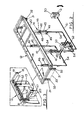
- Fig. 1 is a side elevation with various detail views of a curtainsided van body substantially as disclosed in our aforesaid Patent Specifications and incorporating the present invention;
- Fig. 2 is a diagrammatic perspective view of the roof, spigot-and-socket connections and hydraulic circuit of the van body;
- Fig. 3 is a fragmentary detail view of the front end of the van body;
- Fig. 4 is a perspective view of one of the pillars;
- Fig. 5 is a fragmentary perspective view, to an enlarged scale, of the pillar of Fig. 4;
and - Fig. 6 is a further fragmentary detail view of the upper part of the pillar.
- The curtainsided van body, in this embodiment, is substantially as disclosed in our aforesaid British Patent Specifications and will now be described generally. The description and drawings of our aforesaid Patent Specifications are included herein by reference.
- The
van body 10 in this instance is a wheeled trailer and has afloor 11 with aroof 12 supported above same by a front wall orbulkhead 13, arear frame 14 mounting a pair of hingeddoors 15 and, at each open side of thevan body 10, a pair of longitudinally-spacedpillars 16. - The open sides of the
van body 10 are closable by aplastics curtain 17 suspended byrunners 18 movable along anoverhead track 19 shielded and protected by an external plastics valance orpelmet 20 - The
plastics curtain 17 has at one end (the front end, in this instance) an end pole (not shown) receivable in non-rotatable fashion in top and bottom sockets. The other end of thecurtain 17 has anend pole 21 receivable in a spool element orwrapper 22 has in a hollow end pillar of thevan body 10, theend pole 20 being received by top andbottom spigots 23, 24. The bottom spigot 24 is incorporated in a ratchet tensioner orother winding mechanism 25 used horizontally to tension thecurtain 17 across the open side of thevan body 10. Theratchet tensioner 25, as is known, is locked against movement when thecurtain 17 is across the open side to close same. When theratchet tensioner 25 is released, thecurtain 17 can be opened from either side by disengaging the appropriate end pole. - The
curtain 17 is also constrained or tensioned in the vertical plane when in its open- side closing position. In our aforesaid Patent Specifications this is achieved by means of horizontally-spaced load-bearing straps 26 freely accommodated in vertical sleeves in thecurtain 17 and each secured at the top to arunner 18 and being threaded through eyelets in the exterior wall of each sleeve and finally being threaded through a buckle or tensioner before terminating in a hook or similar 27 engageable on arave 28 secured along thefloor 11 at the open side of thevan body 10. It will be manifest that before thecurtain 17 can be moved to open the van body side each load-bearingstrap 17 requires to be slackened and itshook 27 disengaged from therave 28. - In this instance and for a reason to be amplified upon later, the
rave 28 comprises two vertically-spaced hook-engagingformations frame section 29 secured to aframe section 30 fastened to the side of thefloor 11. Theframe section 29 may be vertically adjustable relative to elevate hook-engagingformation 28A above thefloor 11 if required. - When hook-engaging
formation 28A is being used, thelower formation 28B which lies outboard offormation 28A serves as a rubbing rail to give protection to thecurtains 17 from side damage while thevan body 10 is being used in close or tight packed operations. - The
van body roof 12, according to this invention, is elevatable above and clear of the front bulkhead orwall 13 and therear frame 14 andrear doors 15. - The
roof 12 is vertically movable as a unit and has at or adjacent each corner a dependingspigot 31 freely movable in acomplementary socket 32 secured to the inside of thefront bulkhead 13 and therear frame 14. - The
roof 12 at the front end has a depending barrier orshield 33 in contact with the front face of the front bulkhead orwall 13 to prevent ingress of dirt, dust, rain, etc. as thevan body 10 is travelling. A seal orgasket 34 may be provided on the top edge of the front bulkhead orwall 13 and/or on the underside of theroof 12 to close any gapping between thefront wall 13 and the underside of theroof 12. - The rear end of the
roof 12 has a short dependingpelmet 35 which overlaps therear frame 14 when theroof 12 is down without interfering with the opening and closing of thedoors 15. - The means for raising and lowering the
roof 12 are the supportingpillars 16 and associated hydraulic jacking equipment. - Each
pillar 16 can be swung from an inboard position where it has alongside thevan body roof 12 andfloor 11 through 900 or thereabouts to an outboard position where the pillar is spaced from thevan body roof 12 andfloor 11. - Each
pillar 16 is telescopic and has a lowerinner part 36 and an upperouter part 37. - The
upper pillar part 37 is connected by a right-angled arm 38 pivotally connected to theroof 12 at 39. Theupper pillar part 37 is inwardly cranked at 40 so that in normal travelling position (i.e. pillar inboard position) thearm 38 lies under theroof 12 to provide substantial fore-and-aft support thereto. - The
lower pillar part 36 is also connected to a right-angled arm 41 pivoted to the underside of thefloor 11, thepillar 16, in the region of thefloor 11 being received, in its inboard position, in arecess 42 in thefloor 11. Thepillar 16 has mounted in its lower part 36 a manually-operable spring-loadedlocking pin 43 releasably engagable in an aperture in a locking plate 44 secured in therecess 42. With thepin 43 engaged in the plate 44, thepillar 16 cannot be swung outboard. - A single-acting
hydraulic ram 45 is mounted inside each lowerinner pillar part 36 adjacent its upper end with itspiston rod 46 secured to aplate 47 fixed to the inside of the upperouter pillar part 37. - The hydraulic ram is secured and located in the
inner pillar part 36 by two pairs ofrollers rollers hydraulic ram 45 to twist within thepillars 16. - The hydraulic rams 45 (four in this embodiment) are balanced and are simultaneously operated by a manually
operable pump 50 connected by apipeline 51 to a hydraulic fluid reservoir 5,f- which delivers through aflow divider 53 and pipelines 54 a balanced hydraulic pressure to eachhydraulic ram 45. - The
pipelines 54, at least insofar as their lengths through thearms 41 andpillars 16 are concerned, are in the form of flexible hoses. At thearms 41, thehoses 54 are protected byplates 55 secured to thearms 41 bybrackets 56. - The upper
outer pillar part 37 of eachpillar 36 does not wholly enclose the lower inner pillar part 36 (see Figs. 5 and 6). Theinner pillar part 36, therefore, at the region of eachhydraulic ram 45 has an access opening 57 closable by aremovable plate 58 to allow for ram repair or replacement.' - Also the
pillar parts side holes 59 which, when in register allow a C-bar or other restraint (not shown) to be inserted therethrough mechanically to lock thepillar parts - The outer
upper pillar part 37 is provided with lateral lugs 60 (at least one) whereby if one of thehydraulic rams 45 becomes inoperative a jack (hydraulic or otherwise) can be used between thefloor 11 and a lug 60 to permit the driver or operator to elevate theroof 12 assuming theother rams 45 are operative. - It will be manifest that this procedure can be employed if more than one
ram 45 is inoperative. - With the
curtains 17 released and drawn to one end of thevan body 10 the swinging posts 16 can be used as elevating jacks to raise theroof 12 upwardly clear of the front andrear end - The elevation of the
roof 12 can be effected with thepillars 16 in the inboard or outboard positions and thepillars 16 can be swung between inboard and outboard positions with theroof 12 in elevated position. ' - Also the swinging
pillars 16 permit variation in the length and width of the lateral openings between the front and rear ends and the pillars for cargo loading or unloading. - Normally once the
van body 10 is loaded with theroof 12 elevated the latter would be lowered due to its weight with the hydraulic pressure released from therams 45 to flow back to the reservoir onto the front wall orbulkhead 13 and therear frame 14, thepillars 16 retracting and, if in outboard position, swung into locked inboard position, and thecurtains 17 could then be drawn across the open sides to close same and be both horizontally and vertically tensioned. Thevan body 10 would then be ready for travelling. - It is envisaged, however, that the
van body 10 may be moved between locations with the roof in elevated position. In this case, thepillars 16 would be locked in inboard position in extended condition, thecurtain 17 would be vertically tensioned by its bottom hooks 27 engagingupper frame formation 28A, possibly raised above thefloor 11, and the end poles would have extensions (not shown) secured to their lower ends for securement in the socket at one end and on the spigot 24 at the other end. It is also envisaged that, in this instance, with a horizontal tensioning arrangement as is disclosed in our aforesaid Patent Specifications provision would have to be made to render the spool element orwrapper 22 extendible. - Alternative roof guiding arrangements may be employed.
- One such arrangement may comprise a guide extending above each corner of the roof in the form of a vertical channel closed at its top and forming part of the van body front and rear structures. Within each channel is a guide roller suitably secured to the roof. Thus the roof can be raised and lowered within the confines or limits of the four corner guide channels.
- Another roof guidance arrangement may comprise at each corner of the van body rear and rear structures, a location cone through which extends, preferably with play, a guide rod, the roof being movable vertically of the guide rod and being apertured, or socketted in its lower surface, to sit down on the end structures or pillars with proper and correct location being ensured by the location cones.
- There may at each end of the van body be only a central location cone with suitable lateral guiding means at the roof corners.
- With the aforesaid arrangement a curtainsided van body can now be adapted to carry consolidated loads whereas hitherto these are usually carried by covered wagons which can be stripped to a platform and framework and the load covered with a tarpaulin.
- Also, this invention means that the total inboard height of the van body can be usefully employed.
Claims (19)
Applications Claiming Priority (2)
| Application Number | Priority Date | Filing Date | Title |
|---|---|---|---|
| GB838318928A GB8318928D0 (en) | 1983-07-13 | 1983-07-13 | Curtainsided van bodies |
| GB8318928 | 1983-07-13 |
Publications (2)
| Publication Number | Publication Date |
|---|---|
| EP0132103A1 true EP0132103A1 (en) | 1985-01-23 |
| EP0132103B1 EP0132103B1 (en) | 1988-01-13 |
Family
ID=10545652
Family Applications (1)
| Application Number | Title | Priority Date | Filing Date |
|---|---|---|---|
| EP19840304694 Expired EP0132103B1 (en) | 1983-07-13 | 1984-07-10 | Curtainsided van bodies |
Country Status (7)
| Country | Link |
|---|---|
| EP (1) | EP0132103B1 (en) |
| JP (1) | JPS6076421A (en) |
| AU (1) | AU3059984A (en) |
| CA (1) | CA1239172A (en) |
| DE (1) | DE3468658D1 (en) |
| ES (1) | ES534328A0 (en) |
| GB (1) | GB8318928D0 (en) |
Cited By (13)
| Publication number | Priority date | Publication date | Assignee | Title |
|---|---|---|---|---|
| FR2577865A1 (en) * | 1985-02-26 | 1986-08-29 | Blond Baudouin | Device for lifting up the framework supporting the cover of a transport vehicle |
| GB2185715A (en) * | 1986-01-29 | 1987-07-29 | Cartwright Freight Systems Lim | Van bodies |
| GB2198394A (en) * | 1986-12-05 | 1988-06-15 | Lawrence David Limited | A curtain sided container |
| GB2241205A (en) * | 1990-02-22 | 1991-08-28 | Anthony Frederick Wilson | Vehicle having height adjustable cover |
| FR2702712A1 (en) * | 1993-03-19 | 1994-09-23 | Trouillet Carrosserie | Device for adjusting the height of a roof of a utility vehicle |
| GB2360494A (en) * | 2000-03-22 | 2001-09-26 | Craig John Mckinnon | Trailer having adjustable height roof |
| EP1407912A1 (en) * | 2002-10-11 | 2004-04-14 | Fahrzeugwerk Bernard Krone GmbH | Body structure for commercial vehicle |
| GB2395694A (en) * | 2002-11-30 | 2004-06-02 | Don Bur Service Ltd | Trailer/container having pivotal side pillars |
| DE102008035767A1 (en) * | 2008-07-31 | 2010-02-04 | Fahrzeugwerk Bernard Krone Gmbh | Vehicle body for commercial vehicles |
| US8308417B1 (en) * | 2008-12-18 | 2012-11-13 | Joseph Verrochi | Method and system for transporting, loading, and unloading various types of goods |
| EP2529966A1 (en) | 2011-05-28 | 2012-12-05 | De la Torre San José, Rafael | Variable and optimized aero-shape truck box |
| CN103832254A (en) * | 2012-11-27 | 2014-06-04 | 孙世梁 | Automobile with roof platform |
| EP3170721A1 (en) * | 2015-11-18 | 2017-05-24 | Kögel Trailer GmbH & Co. KG | Roof arch structure, structure for commercial vehicles, swap bridges, and commercial vehicle with body |
Families Citing this family (2)
| Publication number | Priority date | Publication date | Assignee | Title |
|---|---|---|---|---|
| AU658208B2 (en) * | 1991-08-09 | 1995-04-06 | Eldridge, Brenton Andrew | Extendible height gate |
| AU671176B2 (en) * | 1993-01-29 | 1996-08-15 | Barker Trailers Pty. Ltd. | A trailer |
Citations (6)
| Publication number | Priority date | Publication date | Assignee | Title |
|---|---|---|---|---|
| GB1262879A (en) * | 1969-10-10 | 1972-02-09 | Boalloy Ltd | Improvements relating to van bodies |
| GB1262880A (en) * | 1969-10-10 | 1972-02-09 | Boalloy Ltd | Improvements relating to van bodies |
| DE8123700U1 (en) * | 1981-08-13 | 1981-11-19 | Müller, Claus H., 2072 Bargteheide | COMMERCIAL VEHICLES, LIKE VEHICLES OR TRAILERS |
| EP0051931A1 (en) * | 1980-10-24 | 1982-05-19 | Boalloy Limited | Curtainsided vehicles |
| DE3049567A1 (en) * | 1980-12-31 | 1982-07-22 | Heinz-Hubert Ing.(grad.) 4410 Warendorf Wolff | Motor vehicle with load platform - has canopy-supporting frame adjustable for height and width |
| DE8219294U1 (en) * | 1982-07-06 | 1982-11-25 | Peter Amberger Spedition GmbH, 8074 Gaimersheim | VEHICLE WITH ROOF ROOF |
-
1983
- 1983-07-13 GB GB838318928A patent/GB8318928D0/en active Pending
-
1984
- 1984-07-10 DE DE8484304694T patent/DE3468658D1/en not_active Expired
- 1984-07-10 EP EP19840304694 patent/EP0132103B1/en not_active Expired
- 1984-07-12 JP JP14338284A patent/JPS6076421A/en active Pending
- 1984-07-13 CA CA000458864A patent/CA1239172A/en not_active Expired
- 1984-07-13 AU AU30599/84A patent/AU3059984A/en not_active Abandoned
- 1984-07-13 ES ES534328A patent/ES534328A0/en active Granted
Patent Citations (6)
| Publication number | Priority date | Publication date | Assignee | Title |
|---|---|---|---|---|
| GB1262879A (en) * | 1969-10-10 | 1972-02-09 | Boalloy Ltd | Improvements relating to van bodies |
| GB1262880A (en) * | 1969-10-10 | 1972-02-09 | Boalloy Ltd | Improvements relating to van bodies |
| EP0051931A1 (en) * | 1980-10-24 | 1982-05-19 | Boalloy Limited | Curtainsided vehicles |
| DE3049567A1 (en) * | 1980-12-31 | 1982-07-22 | Heinz-Hubert Ing.(grad.) 4410 Warendorf Wolff | Motor vehicle with load platform - has canopy-supporting frame adjustable for height and width |
| DE8123700U1 (en) * | 1981-08-13 | 1981-11-19 | Müller, Claus H., 2072 Bargteheide | COMMERCIAL VEHICLES, LIKE VEHICLES OR TRAILERS |
| DE8219294U1 (en) * | 1982-07-06 | 1982-11-25 | Peter Amberger Spedition GmbH, 8074 Gaimersheim | VEHICLE WITH ROOF ROOF |
Cited By (16)
| Publication number | Priority date | Publication date | Assignee | Title |
|---|---|---|---|---|
| FR2577865A1 (en) * | 1985-02-26 | 1986-08-29 | Blond Baudouin | Device for lifting up the framework supporting the cover of a transport vehicle |
| GB2185715A (en) * | 1986-01-29 | 1987-07-29 | Cartwright Freight Systems Lim | Van bodies |
| GB2185715B (en) * | 1986-01-29 | 1989-11-01 | Cartwright Freight Systems Lim | Van bodies with facilitated side access for loading |
| GB2198394A (en) * | 1986-12-05 | 1988-06-15 | Lawrence David Limited | A curtain sided container |
| GB2241205A (en) * | 1990-02-22 | 1991-08-28 | Anthony Frederick Wilson | Vehicle having height adjustable cover |
| FR2702712A1 (en) * | 1993-03-19 | 1994-09-23 | Trouillet Carrosserie | Device for adjusting the height of a roof of a utility vehicle |
| GB2360494A (en) * | 2000-03-22 | 2001-09-26 | Craig John Mckinnon | Trailer having adjustable height roof |
| EP1407912A1 (en) * | 2002-10-11 | 2004-04-14 | Fahrzeugwerk Bernard Krone GmbH | Body structure for commercial vehicle |
| GB2395694A (en) * | 2002-11-30 | 2004-06-02 | Don Bur Service Ltd | Trailer/container having pivotal side pillars |
| GB2395694B (en) * | 2002-11-30 | 2006-03-08 | Don Bur Service Ltd | Improvements in or relating to trailers or containers |
| DE102008035767A1 (en) * | 2008-07-31 | 2010-02-04 | Fahrzeugwerk Bernard Krone Gmbh | Vehicle body for commercial vehicles |
| US8308417B1 (en) * | 2008-12-18 | 2012-11-13 | Joseph Verrochi | Method and system for transporting, loading, and unloading various types of goods |
| US8911001B1 (en) | 2008-12-18 | 2014-12-16 | Joseph Verrochi | Method and system for transporting, loading, and unloading various types of goods |
| EP2529966A1 (en) | 2011-05-28 | 2012-12-05 | De la Torre San José, Rafael | Variable and optimized aero-shape truck box |
| CN103832254A (en) * | 2012-11-27 | 2014-06-04 | 孙世梁 | Automobile with roof platform |
| EP3170721A1 (en) * | 2015-11-18 | 2017-05-24 | Kögel Trailer GmbH & Co. KG | Roof arch structure, structure for commercial vehicles, swap bridges, and commercial vehicle with body |
Also Published As
| Publication number | Publication date |
|---|---|
| EP0132103B1 (en) | 1988-01-13 |
| DE3468658D1 (en) | 1988-02-18 |
| ES8600135A1 (en) | 1985-10-01 |
| CA1239172A (en) | 1988-07-12 |
| JPS6076421A (en) | 1985-04-30 |
| AU3059984A (en) | 1985-01-17 |
| GB8318928D0 (en) | 1983-08-17 |
| ES534328A0 (en) | 1985-10-01 |
Similar Documents
| Publication | Publication Date | Title |
|---|---|---|
| EP0132103B1 (en) | Curtainsided van bodies | |
| US4966510A (en) | Trailer for transporting golf carts and the like | |
| US4384817A (en) | Vehicle lift for a wrecker truck | |
| US4239438A (en) | Device for lifting and carrying loads on top of pickup trucks | |
| US4597712A (en) | Trailer apparatus for transporting vehicles and other cargo | |
| US5152575A (en) | Manual tarp enclosing system for flat bed trucks | |
| US4092039A (en) | Expandable trailer van | |
| US4451193A (en) | Wheel lift apparatus | |
| US4647270A (en) | Transporting unit for trucks and the like | |
| US3754777A (en) | Automatically operatively positioned and storable outrigger pad | |
| US2867339A (en) | Load carrying vehicles and bodies therefor | |
| US4087007A (en) | Cargo platform system | |
| US5447408A (en) | Boat trailer overhead carrying device | |
| US2867390A (en) | Spool trailer | |
| US4792268A (en) | Apparatus for supporting vehicles and the like | |
| US4383792A (en) | Crane for detachable mounting on a truck bed | |
| US6368034B1 (en) | Multi-use trailer for transporting golf carts and the like | |
| US3467431A (en) | Cover for dump truck bodies | |
| US5718554A (en) | Truck trailer with removable racks | |
| US4861094A (en) | Curtain sided trailers | |
| US3687186A (en) | Boxcar full-side closure | |
| US3348874A (en) | Combination boat-tent-trailer apparatus | |
| US3040917A (en) | Load transporting vehicle | |
| EP0881971A1 (en) | Lifting systems for use with vehicles | |
| US4693650A (en) | Trailer apparatus for transporting vehicles and other cargo |
Legal Events
| Date | Code | Title | Description |
|---|---|---|---|
| PUAI | Public reference made under article 153(3) epc to a published international application that has entered the european phase |
Free format text: ORIGINAL CODE: 0009012 |
|
| AK | Designated contracting states |
Designated state(s): BE DE FR GB IT NL SE |
|
| 17P | Request for examination filed |
Effective date: 19850723 |
|
| GRAA | (expected) grant |
Free format text: ORIGINAL CODE: 0009210 |
|
| AK | Designated contracting states |
Kind code of ref document: B1 Designated state(s): BE DE FR GB IT NL SE |
|
| PG25 | Lapsed in a contracting state [announced via postgrant information from national office to epo] |
Ref country code: NL Effective date: 19880113 Ref country code: IT Free format text: LAPSE BECAUSE OF FAILURE TO SUBMIT A TRANSLATION OF THE DESCRIPTION OR TO PAY THE FEE WITHIN THE PRESCRIBED TIME-LIMIT;WARNING: LAPSES OF ITALIAN PATENTS WITH EFFECTIVE DATE BEFORE 2007 MAY HAVE OCCURRED AT ANY TIME BEFORE 2007. THE CORRECT EFFECTIVE DATE MAY BE DIFFERENT FROM THE ONE RECORDED. Effective date: 19880113 Ref country code: FR Free format text: THE PATENT HAS BEEN ANNULLED BY A DECISION OF A NATIONAL AUTHORITY Effective date: 19880113 Ref country code: BE Effective date: 19880113 |
|
| PG25 | Lapsed in a contracting state [announced via postgrant information from national office to epo] |
Ref country code: SE Effective date: 19880131 |
|
| REF | Corresponds to: |
Ref document number: 3468658 Country of ref document: DE Date of ref document: 19880218 |
|
| EN | Fr: translation not filed | ||
| NLV1 | Nl: lapsed or annulled due to failure to fulfill the requirements of art. 29p and 29m of the patents act | ||
| PLBE | No opposition filed within time limit |
Free format text: ORIGINAL CODE: 0009261 |
|
| STAA | Information on the status of an ep patent application or granted ep patent |
Free format text: STATUS: NO OPPOSITION FILED WITHIN TIME LIMIT |
|
| 26N | No opposition filed | ||
| PG25 | Lapsed in a contracting state [announced via postgrant information from national office to epo] |
Ref country code: DE Effective date: 19890401 |
|
| PGFP | Annual fee paid to national office [announced via postgrant information from national office to epo] |
Ref country code: GB Payment date: 19960701 Year of fee payment: 13 |
|
| PG25 | Lapsed in a contracting state [announced via postgrant information from national office to epo] |
Ref country code: GB Free format text: LAPSE BECAUSE OF NON-PAYMENT OF DUE FEES Effective date: 19970710 |
|
| GBPC | Gb: european patent ceased through non-payment of renewal fee |
Effective date: 19970710 |