EP0132097A2 - Münzzählvorrichtung - Google Patents
Münzzählvorrichtung Download PDFInfo
- Publication number
- EP0132097A2 EP0132097A2 EP84304664A EP84304664A EP0132097A2 EP 0132097 A2 EP0132097 A2 EP 0132097A2 EP 84304664 A EP84304664 A EP 84304664A EP 84304664 A EP84304664 A EP 84304664A EP 0132097 A2 EP0132097 A2 EP 0132097A2
- Authority
- EP
- European Patent Office
- Prior art keywords
- coins
- frame
- counting apparatus
- coin counting
- abutment
- Prior art date
- Legal status (The legal status is an assumption and is not a legal conclusion. Google has not performed a legal analysis and makes no representation as to the accuracy of the status listed.)
- Withdrawn
Links
Images

Classifications
-
- G—PHYSICS
- G07—CHECKING-DEVICES
- G07D—HANDLING OF COINS OR VALUABLE PAPERS, e.g. TESTING, SORTING BY DENOMINATIONS, COUNTING, DISPENSING, CHANGING OR DEPOSITING
- G07D9/00—Counting coins; Handling of coins not provided for in the other groups of this subclass
- G07D9/06—Devices for stacking or otherwise arranging coins on a support, e.g. apertured plate for use in counting coins
-
- G—PHYSICS
- G07—CHECKING-DEVICES
- G07D—HANDLING OF COINS OR VALUABLE PAPERS, e.g. TESTING, SORTING BY DENOMINATIONS, COUNTING, DISPENSING, CHANGING OR DEPOSITING
- G07D9/00—Counting coins; Handling of coins not provided for in the other groups of this subclass
- G07D9/002—Coin holding devices
- G07D9/004—Coin packages
Definitions
- This invention relates to a coin counting apparatus.
- Hitherto coin counting apparatus as used by bank tellers and shopkeepers included a cylindrical container having a fixed volume into which coins were fed until the container was substantially filled which corresponded to a certain amount.
- the volume of the container could be such that it was substantially filled with twenty (20) twenty cent coins which correspond to an amount of four dollars.
- the container was of smaller diameter and was suitably of a size to correspond to a dollar or two dollars worth of coins.
- the coin counting apparatus of the invention includes:
- the resilient frame may be of any suitable type and preferably includes one or more uprights wherein at least a pair of adjacent uprights are resiliently deformable.
- the resilient frame may also include cross members at each end of the frame and intermediate the height of the frame. Suitably each cross member may also be resiliently deformable.
- the pair of adjacent uprights referred to above may be biassed outwardly and one way of achieving this is to bend each upright inwardly.
- each cross member be biassed outwardly and this may be achieved by each cross member being bent inwardly.
- the resilient frame be manufactured from spring steel or wire.
- the resilient frame may comprise a pair of resilient uprights and a third upright which may be also resiliently deformable.
- a pair of top cross members interconnecting each resilient upright to the rigid upright as well as a pair of bottom cross members interconnecting each resilient upright to the rigid upright.
- an access entrance which is bounded on each side by each resilient upright.
- the support means for supporting the resilient frame is preferably an elongate support housing and suitably includes a pair of opposed end walls and a pair of opposed side walls or a continuous side wall and an open top.
- the support housing also includes an access opening bounded by the opposed edges of the side wall.
- the elongate support housing may be oriented in a horizontal plane thus forming a horizontal trough and a plurality of coins making up a predetermined value may be loaded into the trough.
- the upper or surrounding edge portions of the open top of the trough may constitute an appropriate abutment means wherein the resilient frame may be located over the open top and the resilient upright of the access entrance of the resilient frame may be forced inwardly by opposed inner parts of said edge portions to engage the plurality of coins in snap fit relationship.
- abutment means is suitably elongate and includes an abutment wall and optionally a pair of opposed side flanges.
- the abutment wall may be planar or arcuate.
- the support housing is movable relative to the abutment wall although the reverse arrangement is possible if desired.
- a base on which both the support housing and the abutment wall is mounted.
- the support housing may be slidably mounted on the base and the abutment wall rigidly mounted thereto.
- the base may also have an elevated boss or projection located adjacent the abutment wall.
- the support housing may also comprise retaining means for retaining the resilient frame therein.
- this may comprise a magnet located in the continuous side wall thereof which may attract the third upright of the frame described above.
- assembly 10 comprising support housing 11 having end wall 12, opposed side walls 13 and access opening 14.
- Base 16 includes side flanges 17 elevated above the floor 18 of base 16 and end flange 19.
- Support housing 11 is provided with slides 20 which engage in grooves 21 located below side flanges 17 so that housing 11 is slidably movable relative to base 16.
- magnet 15 located in end wall 12 of support housing 11.
- abutment wall 22 having side surfaces 23, arcuate inner surface 24 and end surface 25. Abutment wall 22 is braced by brace 27. There is also shown elevated boss 28 located adjacent abutment wall 22.
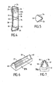
- Resilient frame 29 includes uprights 30 which are bent inwardly as shown at 31 and 32. There is also included intermediate upright 30A which also may be bent inwardly in a similar manner. There is also included top end cross members 34 which may be bent downwardly and bottom cross members 35 which may be bent upwardly so as to provide an outwardly directed bias. There may also be provided one or more intermediate cross members 36 which may rigidify frame 29. Coins 37 are shown retained within the confines of frame 29 through access entrance 38. There is also shown cradle 39 having end lugs 40,floor 41 and side flanges 39A.
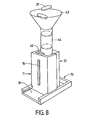
- FIGS 7-8 The operation of the assembly shown in the drawings will now be described as particularly shown in FIGS 7-8.
- the support housing 11 is moved until it is closely adjacent abutment wall 22 to thereby form chamber 42.
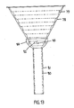
- a funnel 43 having downwardly extending tube 44 is then oriented so that tube 44 extends within the confines of chamber 42.
- Coins 37 are then passed into chamber 42 through tube 44.
- Resilient frame 29 has already been placed in chamber 42 adjacent tube 44 with upright 30A being located adjacent magnet 15 which ensures that frame 29 assumes an upright orientation.
- the funnel 43 is removed.
- the pile of coins is supported by elevated boss 28.
- the apparatus of the invention can be used for counting and sorting of coins on a rapid basis and is more efficient in operation than the prior art described above.
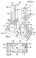
- base 45 having floor or base surface 46 together with keyways or grooves 47 and side flanges 48.
- grooves 49 for locking plates 50 having end'tabs 51.
- Each plate 50 may be accommodated within a retaining recess 52 of base 45.
- abutment block 53 having abutment wall 54, side walls 55 and end walls 56.
- recess or slot 57 having entrance position 57A.
- abutment insert 58 having base slot 59 for engaging with abutment wall 54 as shown in FIG 9.
- Abutment wall 54 is provided with coin retaining groove 60 as well as abutment insert 58 which has body part 62 and end projection 63 which engages with slot 57A.
- Abutment block 58 has slides 64 which engage in an associated groove 47.
- support block 65 having coin retaining boss 66, side walls 67,intermediate wall 68 and end walls 69.
- recess or slot 70 having entrance portion 70A.
- Support block 65 also has slides 71 which engage with grooves 47.
- insert 72 having inner coin retaining slot 73,side walls 74 and end wall 75 having projection 76 which engages with recess 70A as shown.
- Wall 68 of support block 65 engages in slot 77 of insert 72 as shown.
- FIGS 9-10 operates in a similar manner to that shown in FIGS 1-3 with coins 37 as shown in FIG 10 being retained within recess 73 of insert 72 and supported by raised boss 66.
- Resilient frame 29 is retained within groove 61 of abutment insert 58 as shown and upon engagement of coins 37 with frame 29 they are snapped or clipped into the confines of frame 29 and hold therein as shown in FIGS 1-3.
- Inserts 58 and 72 are useful for providing a coin height equivalent to a predetermined value and may be dispensed with if required.
- Support housing 65 may be used for coins of larger diameter and in this case frame 29 engages with groove 60 of abutment housing 53.
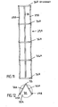
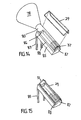
- FIGS 11-12 there is shown resilient frame 29A having intermediate upright 33 end uprights 29B and access entrance 38A. Also shown are cross members 36A. Each upright 29B is curved inwardly between adjacent cross members 36A as shown.
- funnel 78 having interior ribs 79 and base tube 80.
- Funnel 78 may be universal in operation and be used with coins of varying sizes corresponding to a particular coin retaining tube 81 which corresponds to a specific coin diameter.
- Funnel 78 may have bayonet projections 83 which engage with bayonet sockets 82 of tube 81.
- Tube 81 may also be provided with enlarged bowl like end part 84 having sockets 82.
- Ribs 79 are provided for ensuring that coins may pass into tube 81 in a horizontal orientation and thus inhibits jamming of coins.
- funnel 78 may be used to load cradle of horizontal trough 85 as shown with coins 37.
- cradle 85 may be provided with arcuate recess 86 for locating tube 80 of funnel 78 within cradle 85 which is then retained in position by end retaining lug 87.
- Resilient frame 29 may then be held in position above tube 80 which may then be withdrawn while frame 29 is snapped in position about the pile of coins 37 wherein in this case edge portions 88 of cradle 85 may provide suitable abutment means for this purpose and in particular the inner parts of edge portions 88.
- Cradle 85 may also be provided with feet 89 so as to provide an inclined position when supporting funnel 78.
Landscapes
- Physics & Mathematics (AREA)
- General Physics & Mathematics (AREA)
- Control Of Vending Devices And Auxiliary Devices For Vending Devices (AREA)
Applications Claiming Priority (2)
| Application Number | Priority Date | Filing Date | Title |
|---|---|---|---|
| AU310/83 | 1983-07-15 | ||
| AU31083 | 1983-07-15 |
Publications (2)
| Publication Number | Publication Date |
|---|---|
| EP0132097A2 true EP0132097A2 (de) | 1985-01-23 |
| EP0132097A3 EP0132097A3 (de) | 1985-09-18 |
Family
ID=3691124
Family Applications (1)
| Application Number | Title | Priority Date | Filing Date |
|---|---|---|---|
| EP84304664A Withdrawn EP0132097A3 (de) | 1983-07-15 | 1984-07-09 | Münzzählvorrichtung |
Country Status (3)
| Country | Link |
|---|---|
| US (1) | US4570654A (de) |
| EP (1) | EP0132097A3 (de) |
| JP (1) | JPS6043787A (de) |
Families Citing this family (2)
| Publication number | Priority date | Publication date | Assignee | Title |
|---|---|---|---|---|
| JPH0374081U (de) * | 1989-11-22 | 1991-07-25 | ||
| DE20010040U1 (de) * | 2000-06-07 | 2000-09-28 | F. Zimmermann GmbH & Co. KG, 10785 Berlin | Vorrichtung zum Sortieren von Münzen mit einem als Hülsenbehälter ausgebildeten Münzenauffangbehälter |
Family Cites Families (6)
| Publication number | Priority date | Publication date | Assignee | Title |
|---|---|---|---|---|
| US31264A (en) * | 1861-01-29 | Bed-bottom | ||
| US1751615A (en) * | 1928-01-25 | 1930-03-25 | William C Bower | Coin handler |
| US2441486A (en) * | 1946-11-12 | 1948-05-11 | Charles H Hagopian | Coin stacker |
| CH279784A (de) * | 1949-09-13 | 1951-12-15 | Frei Albert | Halter zum Verpacken und Transportieren von Münzen. |
| US2697579A (en) * | 1950-06-29 | 1954-12-21 | Sprague Electric Co | Mounting structure for capacitors or the like |
| GB1548169A (en) | 1975-10-22 | 1979-07-04 | Professional Packaging Ltd | Holder for disc-like objects |
-
1984
- 1984-07-09 EP EP84304664A patent/EP0132097A3/de not_active Withdrawn
- 1984-07-10 US US06/629,453 patent/US4570654A/en not_active Expired - Fee Related
- 1984-07-14 JP JP59146687A patent/JPS6043787A/ja active Pending
Also Published As
| Publication number | Publication date |
|---|---|
| EP0132097A3 (de) | 1985-09-18 |
| JPS6043787A (ja) | 1985-03-08 |
| US4570654A (en) | 1986-02-18 |
Similar Documents
| Publication | Publication Date | Title |
|---|---|---|
| CN111591476B (zh) | 制造卡匣的系统 | |
| US5366069A (en) | Modular coin storage assembly | |
| EP0451917A1 (de) | Fahrbare Behälter | |
| PL169316B1 (pl) | Dozownik do pigulek lub tabletek PL PL PL PL PL PL | |
| US6099401A (en) | Coin sorting apparatus | |
| WO2002071343A1 (en) | Coin bag support system | |
| US4010766A (en) | Change dispensing apparatus | |
| EP0258955A2 (de) | Aufstellbarer Verkaufsautomat für eine Tischfläche oder ähnliches | |
| US5447253A (en) | Condom dispenser | |
| EP0157313B1 (de) | Einsatz für eine Geldschublade | |
| US4570654A (en) | Coin counting apparatus | |
| US4589571A (en) | Vending machine dispensing device | |
| EP1148372A2 (de) | Behälter für Mikroskop-Objektträger | |
| EP0170636A1 (de) | Automatischer Verteiler von Gegenständen durch Gewindegänge mit angetriebenen, beweglichen Trägern | |
| US6443829B1 (en) | Coin sorting apparatus | |
| US5268149A (en) | Universal transportation tray for laboratory volumetric equipment | |
| US3393948A (en) | Dispensing | |
| CN218214243U (zh) | 一种彩票售卖机 | |
| US4934262A (en) | Container for storing newspapers and automatically dispersing twine for bundling newspapers | |
| US3486633A (en) | Bottle receptacle | |
| US5115914A (en) | Container for plastic used glasses | |
| US6755731B2 (en) | Coin assortment box structure of coin sorting machine | |
| US3587925A (en) | Article-vending mechanism | |
| GB2263474A (en) | Dispenser with constant dispensing force | |
| EP0658326A1 (de) | Schaukasten oder Schaugestell |
Legal Events
| Date | Code | Title | Description |
|---|---|---|---|
| PUAI | Public reference made under article 153(3) epc to a published international application that has entered the european phase |
Free format text: ORIGINAL CODE: 0009012 |
|
| AK | Designated contracting states |
Designated state(s): AT BE CH DE FR GB IT LI NL SE |
|
| PUAL | Search report despatched |
Free format text: ORIGINAL CODE: 0009013 |
|
| AK | Designated contracting states |
Designated state(s): AT BE CH DE FR GB IT LI NL SE |
|
| 17P | Request for examination filed |
Effective date: 19860228 |
|
| STAA | Information on the status of an ep patent application or granted ep patent |
Free format text: STATUS: THE APPLICATION IS DEEMED TO BE WITHDRAWN |
|
| 18D | Application deemed to be withdrawn |
Effective date: 19870203 |