EP0132096A2 - Unterteilungselement und Zuschnitt zu seiner Herstellung - Google Patents
Unterteilungselement und Zuschnitt zu seiner Herstellung Download PDFInfo
- Publication number
- EP0132096A2 EP0132096A2 EP84304658A EP84304658A EP0132096A2 EP 0132096 A2 EP0132096 A2 EP 0132096A2 EP 84304658 A EP84304658 A EP 84304658A EP 84304658 A EP84304658 A EP 84304658A EP 0132096 A2 EP0132096 A2 EP 0132096A2
- Authority
- EP
- European Patent Office
- Prior art keywords
- panel
- main
- section
- panels
- partition structure
- Prior art date
- Legal status (The legal status is an assumption and is not a legal conclusion. Google has not performed a legal analysis and makes no representation as to the accuracy of the status listed.)
- Withdrawn
Links
Images


Classifications
-
- B—PERFORMING OPERATIONS; TRANSPORTING
- B65—CONVEYING; PACKING; STORING; HANDLING THIN OR FILAMENTARY MATERIAL
- B65D—CONTAINERS FOR STORAGE OR TRANSPORT OF ARTICLES OR MATERIALS, e.g. BAGS, BARRELS, BOTTLES, BOXES, CANS, CARTONS, CRATES, DRUMS, JARS, TANKS, HOPPERS, FORWARDING CONTAINERS; ACCESSORIES, CLOSURES, OR FITTINGS THEREFOR; PACKAGING ELEMENTS; PACKAGES
- B65D5/00—Rigid or semi-rigid containers of polygonal cross-section, e.g. boxes, cartons or trays, formed by folding or erecting one or more blanks made of paper
- B65D5/42—Details of containers or of foldable or erectable container blanks
- B65D5/44—Integral, inserted or attached portions forming internal or external fittings
- B65D5/48—Partitions
- B65D5/48024—Partitions inserted
- B65D5/48026—Squaring or like elements, e.g. honeycomb element, i.e. at least four not aligned compartments
- B65D5/48032—Squaring or like elements, e.g. honeycomb element, i.e. at least four not aligned compartments made of paper, provided with an at least partial bottom
- B65D5/48034—Squaring or like elements, e.g. honeycomb element, i.e. at least four not aligned compartments made of paper, provided with an at least partial bottom by folding a single blank
Definitions
- the present invention relates to improvements in a partition structure to be inserted in an outer container or box for forming a plurality of partitioning cells therein, which separately accommodate bottles or the like goods, and a blank plate to be assembled into such partition structure.
- the partition structure may be formed of a foldable sheet material such as a paperboard.
- An inner partition structure for separately accommodating a plurality of goods in a container or box has formerly been formed by combining at least two flat sheet elements which have at least one slit,
- partitioning elements In accordance with such a conventional old technic, two kinds of partitioning elements will be required for forming a partition structure which is adapted to form 3 x 2 cells in the container or box with a rectangular shape in its horizontal section. This causes inconvenience in manufacture and storage of such separate elements.
- USP 4 136 815 discloses a one-piece paperboard partition structure which comprises a pair of vertical longitudinal panels spaced from each other in parallel relation, small panels projecting at right angle to each of the longitudinal panels, and a pair of outer panels, each of which is arranged in contact with an outermost panel in the small panels and traverses a vertical end of the longitudinal panels.
- USP 4 155 501 discloses a blank plate to be assembled into a partition structure, which comprises a longitudinal panel with at least one slit and at least one transverse panel detachably connected to one side of the longitudinal panel and having a slit, said transverse panel being separated from the longitudinal panel along a weakened line for assembling into the partition structure.
- Such conventional partition structures as disclosed in said U.S. patents have various disadvantages. Namely, a blank plate for assembling into the former partition structure has relatively large sections to be cut off between the pair of longitudinal panels, which causes a waste of the material sheet. Further, obliquely folding steps are required in its assembling process, which makes an application for an automatic assembling machine troublesome or difficult. A manual operation will be required for assembling the blank plate as disclosed in the latter patent, since the blank plate should be separated into the longitudinal panel and at least one transverse panel and then the transverse panel(s) is(are) attached to the longitudinal panel, so as to engage the slits formed in the panels with each other.
- a principal object of the present invention is to provide a partition structure and a blank plate therefor, which overcome the disadvantages as in the conventional ones.
- a specific object is to provide a partition structure which is inserted into an outer container to form stable cells for accommodating goods therein.
- Another specific object of the invention is to provide a partition structure having an optional number of partitioning fins
- a partition structure to be inserted in an outer container to form a plurality of cells for accommodating goods therein, which comprises at least one double-walled vertical main partition member, at least one partitioning fin formed in a wall of said main partition member, folded up from the wall and having an acutely curved portion at lower end thereof, and a bottom plate connected to a lower side of the wall of said main partition member, said bottom plate being folded up to engage with the notch in said partitioning fin for positioning the latter.
- the bottom plate has a slit engaging with the acutely curved portion of the partitioning fin.
- a specific object is to provide a blank plate for partition structures, which can easily be assembled into the partition structure to make the application of an automatic assembling machine possible.
- Another specific object of the invention is to provide a blank plate for partition structure, which remarkably reduces loss of material sheet therefor,
- a blank plate for partition structures to be inserted in an outer container to form a plurality of cells for accommodating goods therein which comprises a first main panel having at least one section distinguishable from a remaining area by at least one cut line and a folding line, a first side panel connected to one side of said first main panel, a second main panel arranged at a side of said first main panel opposed to said first side panel and having at least one section similar to that in said first main panel but in rotational symmetrical arrangement, and a second side panel connected to said second main panel at a side opposed to said first main panel, each of said sections having an acutely curved cut line portion arranged near said concerned side panel.
- each of the first and second side panels has at least one slit formed in a side opposed to the concerned main panel and on a line extended from the folding line for the concerned section in the concerned main panel.
- One or more panel unit may connectingly be arranged between the first and second main panels, said panel unit comprising a first panel element connected to one of the main panels, a second panel element connected to the first panel element and having a section surrounded by a cut line and a folding line, and a third panel element connectingly arranged between the second panel element and the second or first main panel and having at least one seption similar to that in said first and second main panels.
- the section in the second panel element is similar to the first or second side panel and is preferred to have at least one slit formed in a side opposed to the third panel element and on a line extended from the folding line for the concerned section in the third panel element.
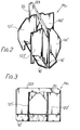
- Figs. 1, 4 and 8 show blank plates BP 1 , BP 2 and BP 3 which are to be assembled into partition structures PS 1 (Figs. 2 and 3), PS 2 (Figs, 5 to 7) and PS 3 (Fig, 9), respectively.
- Each of such blank plates is formed by stamping out from a paperboard or the like thin sheet material along its contour line, 5olid and dot lines in Figs. 1, 4 and 8 show cut and folding lines, respectively.
- the blank plate BP 1 intends to assemble the partition structure PS 1 as shown in Figs. 2 and 3, which forms 2 x 3 cells, when it will be inserted in an outer container (not shown).
- the blank plate BP 1 comprises tandemly arranged panels of a first side panel 10, a first main panel 12, a second main panel 14 and a second side panel 16.
- Each of the main panels 12, 14 has a section 121 or 141 which is arranged substantially in a central portion of the concerned main panel 12 or 14 and surrounded by a cut line 121a or 141a and a folding line 121b or 141b.
- the sections 121 and 141 have a rotational symmetrical configuration with each other.
- Each of the main panels 12, 14 has also another section 122 or 142 which is neighbouringly arranged to the first section 121 or 141 and surrounded by a cut line 122a or 142a and a folding line 122b or 142b.
- the section 122 may have a same configuration with that of the other section 142 but in this embodiment, the former has a smaller area than that of the latter to somewhat save sheet material.
- Each of the sections 121, 122, 141 and 142 has an acutely curved cut line portion 121a', 122a', 141a' or 142a' near the concerned side panel 10 or 16.
- Each of the side panels 10 and 16 has cut lines 101, 102 or 161, 162. A part of such cut lines, which is perpendicular to a longer side of the concerned side panel, is formed on an extension of the folding lines 121b, 142b or 122b, 141b, respectively.
- the blank plate BP 1 as shown in Fig. 1 can be folded to assemble into the partition structure PS as shown in Figs. 2 and 3, in a manner as stated below.
- the first main panel 12 of the blank plate BP 1 is folded up along a central folding line 18, until its surface contacts with that of the second main panel 14 to form an upper edge 201 of a double-walled vertical main partition member 20 (Figs. 2 and 3).
- each of the sections 121, 141 is turned up along the folding lines 121b, 141b, respectively at right angles to each surface of the vertical main partition member 20.
- Each of the other sections 122 and 142 is similarly turned up along the folding lines 122b, 142b, respectively.
- the sections 121, 122, 141 and 142 as turned up hereinbefore serve as partitioning fins 121', 122', 141' and 142' (especially see Fig. 2).
- each of the side panels 10 and 16 are oppositely turned along folding lines 22 and 24, respectively.
- the cut lines 101, 102, 161, 162 formed in the side panels 10, 16 serve as slits to allow insertion of lower endsof the partitioning fins 121', 122', 141', 142', so that the acutely curved cut line portions 121a', 122a', 141a' and 142a', respectively abut to an inner edge of the concerned cut line to stably hold the concerned partitioning fin, as particularly shown in Fig. 2.
- the side plates 10, 16 in the blank plate BP as shown in Fig. 1 function as bottom plates 10', 16' in the partition structure PS 1 as shown in Figs. 2 and 3.
- the main partition member 20 and the partitioning fins 121', 122', 141', 142' form stable cells for separately accommodating the bottles and the bottom plates 10', 16' serve as a member for protecting a bottom of each bottle
- a width of the partitioning fin 122' is smaller than that of the other partitioning fins 121', 141' and 142' but please note that this does not cause any unstableness of the partition structure PS 1 per se in the outer container, since each free vertical side edge of the partitioning fins 121', 141', 142' will abut to an inner wall surface of the outer container.
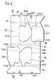
- Figs. 4 and 5 show a second embodiment of the invention.
- the blank plate BP 2 illustrated in Fig. 4 comprises tandemly arranged panels of a first side panel 30, a first main panel 32, a second main panel 34 and a second side panel 36, similar to the blank plate BP 1 shown in Fig. 1.
- a combination of the first main panel 32 and the first side panel 30 has a rotational symmetrical configuration about a mid point between a pair of central folding lines 38, 40 with another combination of the second main panel 34 and the second side panel 36.
- Each of the main panels 32, 34 has two neighbouring sections 321, 322 or 341, 342, respectively, which are similar to the sections 121, 122 or 141, 142 in the blank plate BP 1 as shown in Fig. 1.
- the section 321 (341) is surrounded by a cut line 321a (341a) and a folding line 321b (341b), while the section 322 (342) is surrounded by a cut line 322a (342a) and a folding line 322b (342b), respectively.
- Each of the sections 321, 322, 341 and 342 has an acutely curved cut line portion 321a', 322a', 341a' or 342a' near the concerned side panel 30 or 36.
- the cut line portions 321a' and 341a' are deeper than the other cut line portions.
- Each of the side panels 30 and 36 has cut lines 301, 302 or 361, 362, respectively.
- a part of such cut lines which is perpendicular to a longer side of the concerned side panel, is formed on an extension of the folding lines 321b, 342b or 322b, 341b, respectively.
- the cut lines 301 and 362 are made shorter than the other cut lines. This corresponds to the depth for the acutely curved cut line portions 321a', 322a', 341a', 342a'.
- the blank plate BP 2 as shown in Fig. 4 can be folded to assemble into the partition structure PS 2 as shown in Fig. 5, in a manner similar to that as explained for the first embodiment illustrated in Figs. 1 to 3.
- the main panels 32, 34, the sections 321, 322, 341, 342, and the side panels 30, 36 in the blank plate BP 2 as shown in Fig. 4 form a double-walled vertical main partition 46, partitioning fins 321', 322', 341', 342' and bottom plates 30', 36', respectively in the partition structure PS 2 as shown in Fig. 5.
- the partition structure PS 2 shown in Fig. 5 can be inserted in an outer container OC to accommodate goods such as bottles in separate cells formed by the partition structure PS 2 and an inner surface of the container OC.
- a bottom of the bottle which is shown in ghost line in Fig. 6 presses down the slantly arranged bottom plate 30' or 36' (see Fig. 5) to make the same in flat state as particularly shown in Fig.
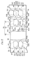
- Figs. 8 and 9 show a third embodiment of the invention.
- the blank plate BP 3 as shown in Fig. 8 intends to assemble the partition structure PS 3 shown in Fig. 9, which forms 4 x 3 cells, when it will be inserted in an outer container (not shown).
- the blank plate BP 3 comprises basically a first side panel 50, a first main panel 52, a second main panel 54 and a second side panel 56 as well as an interpositioning member 58 arranged between the first and second main panels 52, 54, which panels and member are arranged side-by-side.
- the interpositioning member 58 has a blank panel 60, an intermediate panel 62 and a supplementary panel 64.
- the first side panel 50 has three slits 501, 502 and 503 at a free longer side of the panel and perpendicular to a folding line 66.
- the first main panel 52 has three sections 521, 522, 523, each of which is defined by a cut line 521a (522a, 523a) and a folding line 521b (522b, 523b).
- the slits 501, 502, 503 in the side panel 50 are formed on an extension of each folding line 521b, 522b or 523b in the main panel 52.
- the blank panel 60 connected to the first main panel 52 through a double folding line 68 has a width same with that of the main panel and has no portion as in sections 521 to 523 in the main panel 52.
- the intermediate panel 62 connected to the blank panel 60 through a folding line 70 has a relatively large section 621 defined by a cut line 621d and remaining bridging parts 62a, 62b,and has a width somewhat larger than that of the first side panel 50.
- the section 621 has three slits 621a, 621b, 621c which are formed in positions similar to those as in the slits 501 to 503 formed in the side panel 50.
- the supplementary panel 64 having one longer side connected to the intermediate panel 62 through a folding line 72 and the other longer side connected to the second main panel 54 through a double folding line 74,has the same width as that of the main panel and the blank panel 60, and has three sections 621, 622, 623 substantially similar to the sections 521, 522, 523 in the first main panel 52, although a configuration of the section 623 is somewhat different from the section 523, said sections.621 to 623 being defined by a cut line 641a (642a, 643a) and a folding line 641b (642b, 643b), respectively,
- the blank plate BP 3 as shown in Fig. 8 can be folded to assemble into the partition structure PS 3 as shown in Fig. 9, in a manner as stated below.
- each of the first main panel 52 and the blank panel 60 of the blank plate BP 3 are folded down respectively along those folding lines of the double folding line 68, so that a reverse side of the both panels 52, 60 contact with each other to form a first double-walled vertical main partition member 80 having an upper edge 801 (Fig. 9) which corresponds to a portion defined by the double folding line 68.
- the intermediate panel 62 is folded up along the folding line 70 at right angles to the vertical main partition member 80 to form an intermediate horizontal bottom plate 60' (Fig. 9).
- the supplementary panel 64 is folded up along the folding line 72 by a right an g le.
- the second main panel 54 is stepwisedly folded down along the double folding line 74b y aright angle, so that a reverse side of the second main panel 54 contacts with that of the supplementary panel 64 to form a second double-walled vertical main partition member 82 having an upper edge 821 (Fig. 9).
- each of sections in the first main panel 52, the supplementary panel 64 and the second main panel 54 are turned up along the concerned folding lines to form partitioning fins 52l', 522', 523', 641', 642', 643', 541', 542', 543', respectively.
- the partitioning fins shall be kept in position by turning up the first side panel 50 as a first side bottom plate 50' (Fig. 9), the section 621 in the intermediate panel (as an intermediate bottom plate in Fig. 9) and the second side panel 56 as a second side bottom plate (Fig. 9) and by engaging the same with the latters as shown in Fig. 9.
- FIG. 8 and 9 may be modified by continuously arranging the member 58 in two or more to make the number of cells to be formed with an outer container larger.
Landscapes
- Engineering & Computer Science (AREA)
- Mechanical Engineering (AREA)
- Cartons (AREA)
- Details Of Rigid Or Semi-Rigid Containers (AREA)
Applications Claiming Priority (4)
| Application Number | Priority Date | Filing Date | Title |
|---|---|---|---|
| JP106498/83U | 1983-07-11 | ||
| JP10649883U JPS6015817U (ja) | 1983-07-11 | 1983-07-11 | 梱包箱の仕切板 |
| JP145933/83U | 1983-09-22 | ||
| JP14593383U JPS6054511U (ja) | 1983-09-22 | 1983-09-22 | 梱包箱用中仕切板 |
Publications (2)
| Publication Number | Publication Date |
|---|---|
| EP0132096A2 true EP0132096A2 (de) | 1985-01-23 |
| EP0132096A3 EP0132096A3 (de) | 1985-12-27 |
Family
ID=26446613
Family Applications (1)
| Application Number | Title | Priority Date | Filing Date |
|---|---|---|---|
| EP84304658A Withdrawn EP0132096A3 (de) | 1983-07-11 | 1984-07-06 | Unterteilungselement und Zuschnitt zu seiner Herstellung |
Country Status (1)
| Country | Link |
|---|---|
| EP (1) | EP0132096A3 (de) |
Cited By (1)
| Publication number | Priority date | Publication date | Assignee | Title |
|---|---|---|---|---|
| US5020921A (en) * | 1990-08-02 | 1991-06-04 | International Paper Company | Paperboard partition |
Family Cites Families (3)
| Publication number | Priority date | Publication date | Assignee | Title |
|---|---|---|---|---|
| FR1440093A (fr) * | 1965-04-14 | 1966-05-27 | Cassard S A G | Cloisonnage pour l'emballage de bouteilles dans une caisse |
| FR1595341A (de) * | 1968-12-18 | 1970-06-08 | ||
| US4007830A (en) * | 1975-11-17 | 1977-02-15 | The Mead Corporation | Article carrier partition insert |
-
1984
- 1984-07-06 EP EP84304658A patent/EP0132096A3/de not_active Withdrawn
Cited By (1)
| Publication number | Priority date | Publication date | Assignee | Title |
|---|---|---|---|---|
| US5020921A (en) * | 1990-08-02 | 1991-06-04 | International Paper Company | Paperboard partition |
Also Published As
| Publication number | Publication date |
|---|---|
| EP0132096A3 (de) | 1985-12-27 |
Similar Documents
| Publication | Publication Date | Title |
|---|---|---|
| US20040113893A1 (en) | Position determination II - calculation | |
| EP0150136A3 (de) | Verpackungskarton zum Enthalten von mehreren Behältern | |
| US5518171A (en) | Partition and container | |
| US3767106A (en) | Container partitions | |
| EP0489003B1 (de) | Bodenverschluss für kartons | |
| US3770184A (en) | Internal partitioning of compartmented cases | |
| EP0132096A2 (de) | Unterteilungselement und Zuschnitt zu seiner Herstellung | |
| US5984168A (en) | One piece trio of diamond shaped cartons | |
| US4225039A (en) | Container case and blank therefor | |
| US4000844A (en) | One-piece partition | |
| CA2566114A1 (en) | Interlocking dividers | |
| US4736846A (en) | Display packaging for a plurality of aligned drinking glasses or similar articles | |
| US4379518A (en) | Three cell divider for carton | |
| JP4365268B2 (ja) | カートンブランク | |
| JPH1135081A (ja) | 薬瓶収納箱 | |
| JP2001354229A (ja) | 段ボールのロック機構及びトレー | |
| US3394864A (en) | Carry-out tray having end wall panels | |
| EP0518402B1 (de) | Stapelfähiger Flaschenkasten | |
| US4308949A (en) | Dispensing carton for small bottles | |
| US4274579A (en) | Cellular tray-type carton | |
| US3834608A (en) | Compartmented tray | |
| IES922637A2 (en) | Carton divisions | |
| JPH089024Y2 (ja) | 瓶包装用仕切りと仕切り付き包装箱 | |
| JPH0311138Y2 (de) | ||
| US4253565A (en) | Carrier partition arrangement |
Legal Events
| Date | Code | Title | Description |
|---|---|---|---|
| PUAI | Public reference made under article 153(3) epc to a published international application that has entered the european phase |
Free format text: ORIGINAL CODE: 0009012 |
|
| AK | Designated contracting states |
Designated state(s): CH DE FR GB LI NL |
|
| PUAL | Search report despatched |
Free format text: ORIGINAL CODE: 0009013 |
|
| AK | Designated contracting states |
Designated state(s): CH DE FR GB LI NL |
|
| 17P | Request for examination filed |
Effective date: 19860625 |
|
| 17Q | First examination report despatched |
Effective date: 19870217 |
|
| STAA | Information on the status of an ep patent application or granted ep patent |
Free format text: STATUS: THE APPLICATION IS DEEMED TO BE WITHDRAWN |
|
| 18D | Application deemed to be withdrawn |
Effective date: 19870630 |