EP0132084B1 - Apparatus for the separation of mixtures of materials of different consistencies such as meat and bone - Google Patents
Apparatus for the separation of mixtures of materials of different consistencies such as meat and bone Download PDFInfo
- Publication number
- EP0132084B1 EP0132084B1 EP84304586A EP84304586A EP0132084B1 EP 0132084 B1 EP0132084 B1 EP 0132084B1 EP 84304586 A EP84304586 A EP 84304586A EP 84304586 A EP84304586 A EP 84304586A EP 0132084 B1 EP0132084 B1 EP 0132084B1
- Authority
- EP
- European Patent Office
- Prior art keywords
- pump
- chamber
- rotor
- vane
- separator
- Prior art date
- Legal status (The legal status is an assumption and is not a legal conclusion. Google has not performed a legal analysis and makes no representation as to the accuracy of the status listed.)
- Expired
Links
- 239000000203 mixture Substances 0.000 title claims abstract description 45
- 238000000926 separation method Methods 0.000 title claims abstract description 25
- 239000000463 material Substances 0.000 title claims abstract description 17
- 210000000988 bone and bone Anatomy 0.000 title abstract description 36
- 235000013372 meat Nutrition 0.000 title abstract description 35
- 238000006073 displacement reaction Methods 0.000 claims abstract description 12
- 239000011343 solid material Substances 0.000 claims abstract description 5
- 238000010008 shearing Methods 0.000 claims description 14
- 238000011144 upstream manufacturing Methods 0.000 claims description 6
- 230000000717 retained effect Effects 0.000 claims description 5
- 230000007423 decrease Effects 0.000 claims description 3
- 239000010865 sewage Substances 0.000 abstract description 4
- 238000007789 sealing Methods 0.000 abstract 1
- 238000004519 manufacturing process Methods 0.000 description 5
- 238000010276 construction Methods 0.000 description 4
- 235000013305 food Nutrition 0.000 description 4
- 239000002245 particle Substances 0.000 description 4
- 241000251468 Actinopterygii Species 0.000 description 3
- 241000287828 Gallus gallus Species 0.000 description 3
- 235000013330 chicken meat Nutrition 0.000 description 3
- 230000000295 complement effect Effects 0.000 description 3
- 239000007787 solid Substances 0.000 description 3
- 241001465754 Metazoa Species 0.000 description 2
- 230000033228 biological regulation Effects 0.000 description 2
- 238000013461 design Methods 0.000 description 2
- 238000010586 diagram Methods 0.000 description 2
- 235000019688 fish Nutrition 0.000 description 2
- 238000011282 treatment Methods 0.000 description 2
- 206010042618 Surgical procedure repeated Diseases 0.000 description 1
- 238000013459 approach Methods 0.000 description 1
- 235000015278 beef Nutrition 0.000 description 1
- 210000001124 body fluid Anatomy 0.000 description 1
- 239000010839 body fluid Substances 0.000 description 1
- 210000000481 breast Anatomy 0.000 description 1
- 230000015556 catabolic process Effects 0.000 description 1
- 238000012937 correction Methods 0.000 description 1
- 238000006731 degradation reaction Methods 0.000 description 1
- 230000002939 deleterious effect Effects 0.000 description 1
- 239000003814 drug Substances 0.000 description 1
- 229940079593 drug Drugs 0.000 description 1
- 230000009977 dual effect Effects 0.000 description 1
- 230000000694 effects Effects 0.000 description 1
- 238000000227 grinding Methods 0.000 description 1
- 239000007788 liquid Substances 0.000 description 1
- 230000013011 mating Effects 0.000 description 1
- 235000013622 meat product Nutrition 0.000 description 1
- 239000000320 mechanical mixture Substances 0.000 description 1
- 238000000034 method Methods 0.000 description 1
- 238000003801 milling Methods 0.000 description 1
- 210000003739 neck Anatomy 0.000 description 1
- 235000015277 pork Nutrition 0.000 description 1
- 230000000750 progressive effect Effects 0.000 description 1
- 238000012552 review Methods 0.000 description 1
- 229910001220 stainless steel Inorganic materials 0.000 description 1
- 239000010935 stainless steel Substances 0.000 description 1
- XLYOFNOQVPJJNP-UHFFFAOYSA-N water Substances O XLYOFNOQVPJJNP-UHFFFAOYSA-N 0.000 description 1
Images




Classifications
-
- A—HUMAN NECESSITIES
- A22—BUTCHERING; MEAT TREATMENT; PROCESSING POULTRY OR FISH
- A22C—PROCESSING MEAT, POULTRY, OR FISH
- A22C17/00—Other devices for processing meat or bones
- A22C17/04—Bone cleaning devices
Definitions
- the apparatus consists of a frame 10 providing a hopper 12 into which the meat and bone mixture to be separated is delivered.
- the hopper contains a longitudinal conveyor screw 14 rotated about a horizontal axis by a drive rotor (not shown) via a connecting drive gear 16 and a splined drive output shaft 18 mounted in a bearing 20 in an end plate of the frame.
- Special bearing seals such as 22 are required, as is well known to those skilled in the art of food handling machinery construction, to prevent entry to the bearings of the body fluids that accompany meats.
- the hopper body is provided with a front end flange 24 to which is fastened the adjacent rear end mounting flange 26 of a rotary, radial-vane, positive-displacement pump indicated generally by the reference 28.
- the pump comprises a cylindrical housing 30 having the rear mounting flange 26 at one end and a comparable front mounting flange 32 at the other end.
- Front and rear bearing plates 34 and 36 respectively are mounted in the cylindrical housing on either side of a hollow cam plate 38, so as to form the pump chamber between them.
- Both blades are of an axial width to fit without appreciable play between the two facing axial faces of the end bearing plates, and they are both provided with mating complementary half-width radially elongated slots 58a and 58b respectively to permit the required radial sliding movements in the rotor boss as it rotates about the axis 58.
- the tips 60 of the blades engage an internal cam constituted by the inside surface 62 of the bore in the hollow cam plate 38, the tips being rounded to facilitate the rubbing contact as they move over the surface.
- the surface 62 is generated so that at all times during the rotation of the pump rotor the blade tips are in contact with it, so that the contents of the pump chamber are positively displaced through the pump from the inlet to the outlet, and relatively high pump pressures, e.g. usually from 70-210 Kg/sq. cm (1000-3000 p.s.i.), can readily be generated.
- relatively high pump pressures e.g. usually from 70-210 Kg/sq. cm (1000-3000 p.s.i.
- the chamber encloses an elongated feed screw 84 mounted by splined front rotor end 46 and a bearing 86 for rotation about an axis coaxial with the pump axis 58, and driven in such rotation by the rotor end 46.
- Rotation of the screw 84 conveys the pump-pressurised mixture of meat and bone along the interior of the cylindrical separation chamber 70, the pressure being such that the softer meat is squeezed through the separator screen 76 to the outside (i.e. downstream) separator surface, constituting in this embodiment the meat fraction outlet, from which it will fall into a suitable collector receptacle (not shown), while the bone and unseparated meat eventually exit from an annular bone fraction outlet 88 to another respective collector receptacle (also not shown).
- a suitable collector receptacle not shown
- the bone and unseparated meat eventually exit from an annular bone fraction outlet 88 to another respective collector receptacle (also not shown).
- the maximum arc shall be of constant radius R, and this is the arc ACB at 128 with chord equal to the blade length L. Some correction must be made to L to account for the width of the blade and for the rounded tips of radius W/2.
- the variable cam radius r measured from centre 128 will vary with the angle 6 and can be calculated geometrically, but an exact equation solution is not easily attainable. The problem is particularly suited to an iterative approach, especially with the use of a computer to effect the relative large number of calculations required to obtain the values of the cam radius necessary for the required accuracy of manufacture.
Landscapes
- Life Sciences & Earth Sciences (AREA)
- Engineering & Computer Science (AREA)
- Wood Science & Technology (AREA)
- Zoology (AREA)
- Food Science & Technology (AREA)
- Rotary Pumps (AREA)
- Processing Of Solid Wastes (AREA)
- Meat, Egg Or Seafood Products (AREA)
- Filtration Of Liquid (AREA)
- Extraction Or Liquid Replacement (AREA)
- Structures Of Non-Positive Displacement Pumps (AREA)
- Processing Of Meat And Fish (AREA)
Abstract
Description
- The present invention is concerned with apparatus for the separation of mechanical mixtures of materials of different consistencies, such as a mixture of meat and bone, or a mixture of water and solid material such as sewage.
- Processes and apparatus for the separation of mixtures of materials of different consistencies into component parts are employed in many different industries. For example, in sewage treatment it is necessary at some stage to separate as much as possible of the liquid components of the sewage from the various more solid components, so that they can be subjected separately to appropriate treatments. The presence of the solid components causes considerable difficulty in the handling of the mixtures prior to. their separation.
- The mechanical separation of mixtures of meat and bone into separate components is not a well-established industry. Although usually the machines were proposed for use with different animal and fish species, in practice the earlier machines were operable most successfully with chicken parts, where the difference in consistencies between the meat and the bone is adequate, but the bones are not too difficult to break without splintering and powdering. Attempts to use the machine with other meats, such as beef, pork and fish, were not as successful. Even with chicken, problems were and still are encountered when attempting to obtain maximum production from a machine, such as too much bone content in the meat fraction, beyond the limits permitted by the licensing authorities, or too great a temperature increase in the meat fraction during separation, resulting in lowering in quality and texture of the separated meat.
- A separating apparatus that proved particularly commercially successful is described in U.S. Patent Specifications Serial No. 4,025,001 and 4,069,980, issued respectively 24th May 1977 and 24th January 1978.
- GB-A-1318742 discloses apparatus for the separation of mixtures of materials of different consistencies into separate fractions thereof at an operative separation pressure, comprising an apparatus body having an inlet for the mixture to be separated and respective outlets for the separated fractions, and separator screen means, whose downstream face constitutes the outlet for the separated first fraction, mounted by the said body and having an upstream face against which the mixture from the inlet at the operative separation pressure is delivered, for the corresponding first fraction thereof to pass through the separator screen means to the downstream face thereof, and for the remaining second fraction to be retained by the separator screen means and to pass to said outlet for the retained fraction and a rotary vaned pump between the mixture inlet and the said upstream face of the separator screen means, said pump having a pump chamber receiving the mixture from the inlet and a pump rotor carrying at least one vane rotatable about an axis for pressurizing the mixture in the pump chamber to said operative separation pressure. This prior art apparatus mentions the use of a rotary vaned stainless steel pet food pump to feed the incoming mixture to a conveyor screw cooperating with the separator screen means.
- It is the principal object of the invention to provide an improved apparatus for the separation of mixtures of materials of different consistencies, such as mixtures of meat and bone capable of higher operative separation pressures than in the prior art apparatus.
- Accordingly the present invention is characterised in that the rotary vaned pump has a delivery pressure of from 70 to 210 kg/cm2 (1,000 to 3,000 Ibs/in2); in that the pump chamber is mounted within the said body; in that the said at least one vane is of fixed radial length extending on both sides of the pump rotor axis and mounted in a respective radially-extending slot in the rotor and moving radially therein as the rotor rotates; in that the said pump chamber is formed about a chamber longitudinal axis which is radially displayed from said rotor axis of the rotation so that each pump compartment formed by the at least one pump vane decreases in volume as the at least one pump vane moves from an inlet opening to the pump chamber toward an outlet opening from the pump chamber and increases in volume as the at least one pump vane moves from the outlet opening toward the inlet opening; and in that the interior face of the pump chamber circumferential wall constitutes an interior cam face moving the at least one pump vane radially in the pump rotor as the pump rotor rotates with both radial edges of the at least one pump vane in operative contact with said interior cam face.
- Separators which are particular preferred embodiments of the invention will now be described, by way of example, with reference to the accompanying diagrammatic drawings, wherein:-
- Figure 1 is a longitudinal cross-section through a first embodiment, in which a positive displacement pump feeds the mixture to be separated to a separate, attached separating unit;
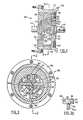
- Figure 2 is a similar cross-section, to a larger scale, through the positive displacement pump of the separator of Figure 1, in order to show the construction thereof, taken on the line 2-2 in Figure 3;
- Figure 3 is a plane cross-section taken on the line 3-3 in Figure 2;
- Figure 3A is a plane cross-section of a detail of a vane of the pump of Figures 2 and 3, taken on the line 3A-3A of Figure 3;
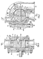
- Figure 4 is a longitudinal cross-section through a second embodiment, in which the separating unit is an integral part of the positive displacement pump, the section being taken on the line 4-4 in Figure 5;
- Figure 5 is a transverse cross-section of the embodiment of Figure 4, taken on the line 5-5 in Figure 4;
- Figure 6 is a longitudinal cross-section through a third embodiment, again in which the separating unit is an integral part of the positive displacement pump, the section being taken on the line 6-6 in Figure 7;
- Figure 7 is a transverse cross-section taken on the line 7-7 in Figure 6;
- Figure 8 is a front elevation of a separator element for use in the embodiments of Figures 4 through 7;
- Figures 9 and 10 are respective side elevations of two different groups of separator elements for use in the embodiments of Figures 4 through 7;
- Figures 11 and 12 are respective front elevations of portions of a unitary separator element for use in the embodiments of Figures 4 through 7;
- Figure 13 is an outline diagram of the internal cam face of the positive displacement pump in side elevation and a rotor blade to accompany a description of a manner of calculating the cam face profile to permit its manufacture.
- Figure 14 is a longitudinal cross-section similar to Figure 1 through a fourth embodiment; and
- Figures 15 and 16 are perspective views respectively of two further forms of separator element for use in the embodiments of Figures 1 and 14.
- The same references will be used if possible for similar parts in all the figures of the drawings.
- The apparatus of Figures 1 through 3A is intended principally for the mechanical separation of various kinds of meats from the bones to which they are attached. A substantial industry has developed, based on the use of such machines, since they are able economically to remove a substantial proportion of edible meat from fowl, animal and fish parts that would otherwise be discarded for food purposes, such us the necks and backs of chickens that have been cut in pieces for separate sale of the legs, breasts and wings. In practice the separation cannot be complete and the separated bone fraction will still contain some meat, while the separated meat fraction will also contain a small amount of bone in the form of tiny particles thereof. Food licensing authorities have instituted strict regulations as to the maximum overall percentages of bone and maximum particle size of the bone that is permitted in the resultant meat products. For example, the regulations of the U.S. Food and Drug Administration permit a maximum bone content of 2% by weight and a maximum bone particle size of 0.5 mm. These standards are difficult to achieve.
- The apparatus consists of a
frame 10 providing ahopper 12 into which the meat and bone mixture to be separated is delivered. The hopper contains alongitudinal conveyor screw 14 rotated about a horizontal axis by a drive rotor (not shown) via a connectingdrive gear 16 and a splineddrive output shaft 18 mounted in abearing 20 in an end plate of the frame. Special bearing seals such as 22 are required, as is well known to those skilled in the art of food handling machinery construction, to prevent entry to the bearings of the body fluids that accompany meats. - The hopper body is provided with a
front end flange 24 to which is fastened the adjacent rearend mounting flange 26 of a rotary, radial-vane, positive-displacement pump indicated generally by thereference 28. Referring now especially to Figures 2, 3 and 3A, the pump comprises acylindrical housing 30 having therear mounting flange 26 at one end and a comparablefront mounting flange 32 at the other end. Front andrear bearing plates hollow cam plate 38, so as to form the pump chamber between them. The pump rotor is provided with two cylindricalplain bearing portions hopper conveyor screw 14. Both ends of the pump rotor protrude from the respective bearing plates and are splined, therear rotor end 44 engaging in the adjacent end of theconveyor screw 14 to be driven thereby, while thefront rotor end 46 engages in the rear end of another conveyor screw to be described below. The assembly of end plates, cam plate and rotor is retained in the housing by aretainer ring 48 screw-threaded into the front end of thehousing 30. - A circumferentially elongated
axial inlet 50 to the pump chamber is provided in therear end plate 36 and a circumferentially elongatedaxial outlet 52 is provided in thefront end plate 34, the two openings being disposed diametrically opposed from one another about the axis of rotation of the rotor. The pump has two radially-extending pump vanes orblades rotor boss 56, the two slots and therefore the two blades being disposed at right angles to one another. Both blades are of an axial width to fit without appreciable play between the two facing axial faces of the end bearing plates, and they are both provided with mating complementary half-width radiallyelongated slots tips 60 of the blades engage an internal cam constituted by theinside surface 62 of the bore in thehollow cam plate 38, the tips being rounded to facilitate the rubbing contact as they move over the surface. Thesurface 62 is generated so that at all times during the rotation of the pump rotor the blade tips are in contact with it, so that the contents of the pump chamber are positively displaced through the pump from the inlet to the outlet, and relatively high pump pressures, e.g. usually from 70-210 Kg/sq. cm (1000-3000 p.s.i.), can readily be generated. The manner in which such a cam surface is determined is described below. - The leading edges of the pump blades adjacent to the
rear bearing plate 36 are hollow ground at 64 (Figure 3A) and hardened to formcutting edges 66. The trailing edge of theinlet 50 is also provided at 68 with a shearing edge that will cooperate with thevane cutting edges 66 to shear any hard material, such as a piece of bone, that protrudes through theinlet 40 into the pump chamber. The bone pieces are moved by the respective blade through the pump chamber and out through theoutlet 52. If the bone piece jams in the outlet it will be sheared against theoutlet trailing edge 68 by the following blade, the sheared off piece being carried around until it can be expelled at a subsequent passage of the blade over the outlet. - The mixture of meat and bone pieces is fed from the
outlet 52 into a separator chamber indicated generally by the reference 70 (Figure 1). In this embodiment this chamber is constituted by arear end plate 72 that is secured to the pumpfront end plate 34 by acircumferential clamp ring 74. The separator chamber provides a cylindrical separator or filter constituted by a large plurality ofannular separator plates 76 that are tightly clamped together between therear end plate 72 and afront end plate 78 by a number of heavy axial circumferentially-spacedtie bolts 80. the separator plates are held aligned with one another to provide a smooth internal (i.e. upstream) cylindricalfront face 81 byaxial aligning bars 82 engaged in radial slots in the plates. The chamber encloses anelongated feed screw 84 mounted by splinedfront rotor end 46 and abearing 86 for rotation about an axis coaxial with the pump axis 58, and driven in such rotation by therotor end 46. Rotation of thescrew 84 conveys the pump-pressurised mixture of meat and bone along the interior of thecylindrical separation chamber 70, the pressure being such that the softer meat is squeezed through theseparator screen 76 to the outside (i.e. downstream) separator surface, constituting in this embodiment the meat fraction outlet, from which it will fall into a suitable collector receptacle (not shown), while the bone and unseparated meat eventually exit from an annularbone fraction outlet 88 to another respective collector receptacle (also not shown). For more details of the construction and operation of this type of separator unit reference may be made to prior U.S. Patent Specifications Serial Nos. 4,025,001 and 4,069,980, the disclosures of which are incorporated herein by this reference. - In the above-described prior apparatus the hopper and separator feed screws, corresponding to the two
screws positive displacement pump 28. The conveyor screws inherently will add a small amount to the pressurisation, but this will not be significant compared to that provided by the pump. - Since the hopper and separator feed screws 14 and 84 are now relieved of the task of pressurising the mixture their design becomes much less onerous and critical. The use of the positive displacement pump, which also acts to break the bones cleanly to suitable size, permits close control of the pressure produced with greatly reduced dependence upon the nature of the mixture and the relative proportions of bone and meat that are present. In the prior art apparatus as represented by those described in the above-mentioned U.S. patent Specifications, the screw conveyors had the dual function of pressurising the mixture and also conveying it through the apparatus, and the pressures which the two screws, particularly the separator screw, were able to apply to the mixture depended in a complicated manner on the relative friction between the meat/bone mixture, the screw body and the upstream face of the separator, and the maximum shear to which the meat or bone could be subjected. The friction also of course differed for different types of meat, and also differed among meats of the same type, depending for example on the proportion of fat present. An optimum condition for good separation is a relatively steady high pressure, but high pressures are difficult to achieve with single screw conveyors. Higher pressures can be obtained with twin screw conveyors, but these are difficult and expensive to design, manufacture and maintain. Attempts to increase the pressure simply by increasing the speed of rotation can easily lead to a situation in which the screw conveyor is shearing the meat without increasing the pressure, resulting in excessive temperature rise and degradation of the quality and texture of the meat fraction.
- In the apparatus of the invention the positive displacement pump pressurises the mixture without any substantial shearing, except minor amounts at the entry and exit openings, and the conveyors need only convey the material without pressurisation. The
screw conveyor 84 must be of smaller volume between successive lands along its length toward thebone fraction exit 88 to take account of the decrease of product volume radially through the filter. Some adjustment of rotational speed may be desirable to take account of different proportions of meat and bone. Thus, if the proportion of bone is high it would be desirable, though not essential, to employ a higher rotational speed of theconveyor 84 in order to expel the larger quantity of bone and maintain the output of the apparatus as high as possible. - Figures 4 and 5 illustrate a second embodiment in which the
positive displacement pump 28 has an axial inlet as with the pump of the apparatus of figures 1 to 3, but has two radial outlets from the pump chamber in the circumferential wall thereof, one of which is constituted bycircumferential separator plates 76 through which the separated meat fraction is expressed to acorresponding outlet 90 from thecasing 30, and the other of which is theoutlet 88 for the bone fraction. This embodiment therefore provides an exceptionally compact form of the apparatus. The apparatus is also suited to any other application in which at least some separation is required into two components of different consistencies, for example some dewatering of a sludgy material. - In this embodiment the
hollow cam plate 38 having an arc of its wall constituted by theseparator elements 76 is mounted in a hollowannular support member 92, which is in turn rotatably mounted in thehousing 30 for rotation about the axis of rotation of the rotor. The hollow cam plate can therefore be rotated relative to the rotor to adjust the timing of the cam and the location of theoutlet 88 relative to the point of minimum volume of thechamber 70 defined by the cam, so as to take account of differences in the relative volumes of the two fractions to be produced by the apparatus. In this embodiment the rotations of the cam is effected by ashaft 94 mounted in abore 96 of the housing for longitudinal movement under the control of a linear operating rotor device (not shown) such as a hydraulic piston and cylinder motor. Theshaft 94 is provided at 98 with rack teeth which mesh with cooperating rack teeth that extend over asector 100 of the outer periphery of thesupport member 92. Theoutlets casing 30 for the two separated fractions are-of greater circumferential extent than the correspondingoutlets 52 andseparator 76 to be able to accommodate this rotation of the cam. - Since the apparatus is not required to drive any other piece of apparatus the
end plate 34 provides an annular bearing for the adjacent rotor end and is secured to thecasing 30 byquick release bolts 104. At the other side the apparatus is provided with anend closure plate 106 bolted to thecasing 30 and supporting athrust bearing 108. Thesupport member 92 completely encloses thecam plate 38 and in so doing also serves to retain in position theseparator elements 76 against the relatively high radially outwardly acting pressure of the material passing through it. - The embodiment of Figures 6 and 7 is functionally similar to that of Figures 4 and 5, the essential difference being that the
inlet 50 th pump chamber and the associated inlet 110 to thecasing 30 are both radial. The hollow ground portions and associated shearing knife edges must therefore be provided at the tips of the vane blades. - Figure 8 shows in greater detail a structure for the
arcuate separator element 76 as employed in the embodiments of Figures 4 through 7, as seen in side elevation, while Figures 9 and 10 show different forms of element in end elevation. With the form of element illustrated by Figures 8 and 9, each element comprises acentral web 112 that remains from the removal of material from a thick plate to leave a narrow arcuate radially-inner portion 114. Thisportion 114 is provided withradial slots 116 through which the separated soften component flows, while the harder component is moved by the vane blades over the separatorinner surface 81, which in this embodiment, at this part of the chamber, also constitutes part of thecam surface 62. A plurality of such elements are assembled together and tightly packed with plainflat spacing elements 118 between each two adjacent elements. - In the embodiment illustrated by Figures 8 and 10 together the
portion 114 is left at one side only of the element and theslots 116 are formed in this one side, so that the elements can be packed tightly together without the need for intermediate plane flat elements. Figures 11 and 12 showunitary filter structures 120 that can be used in place of the stack of elements consisting of a suitably fashioned sheet provided with a large plurality of round holes 122 (Figure 11) or slots 124 (Figure 2) elongated in the direction of movement of the rotor blates. - Figure 13 shows diagrammatically the side elevation of the
cam face 62 and asingle vane 54a stopped in one position. The diagram shows the centre line t, of the rotor having its center of rotation at 126, and the centre line Ø2 of the cam having its centre of rotation at 128. The distance between the two centres is the eccentricity E which is known. The blade length L and thickness W are also known. The centre line of the blades must always pass through thecentre 126 while the eccentricity E is directly proportional to the volume output of the pump and locates theimaginary centre 128 bfthe cam. The rotor blades must seal the spaces between the rotor blades at all times, and therefore must at all times and in all positions of the rotor be in touch with the cam at both ends. - It is arbitrarily chosen that the maximum arc shall be of constant radius R, and this is the arc ACB at 128 with chord equal to the blade length L. Some correction must be made to L to account for the width of the blade and for the rounded tips of radius W/2. The variable cam radius r measured from
centre 128 will vary with theangle 6 and can be calculated geometrically, but an exact equation solution is not easily attainable. The problem is particularly suited to an iterative approach, especially with the use of a computer to effect the relative large number of calculations required to obtain the values of the cam radius necessary for the required accuracy of manufacture. - A value known to be a practical value is assumed for the angle a between the blade centre line and a radius through the
centre 128. Angle (3 can then be determined for any subsequent value of a knowing that the sum of angles a+6+Q must be 90 degrees. - The values of variable cam radius r can then be calculated from the relationships


- Other forms of rotary vaned pumps may also be employed in which the vanes are of fixed length, for example a pump of the type in which the vanes are mounted in radial slots in the rotor with their parallel largest faces parallel to the axis of rotation; the two radially-extending edges of each vane engage complementary face cams on two facing end walls and, as the rotor rotates, cause the vanes to slide axially of the rotor in their radial slots to vary cyclically the volumes of the chambers formed between the rotor and the end wall face cams. The shearing knife edge will, as with the previously-described embodiments, be provided at the edges which traverse the inlet aperture. However, such a structure requires the accurate production of two complementary face cams and their subsequent assembly facing one another and spaced accurately apart, so that the resulting construction is substantially more expensive than those described above.
- Another embodiment of the invention is illustrated by Figure 14, which is similar to the embodiment of Figures 1-3. Since, as explained above, the
screw 84 is no longer required to pressurise the mixture in thechamber 70, it can be made somewhat shorter in length and substantial clearances can be provided between its exterior surface and the interior surface of theseparator elements 76. In this embodiment the screw is designed and arranged to apply a pulsating radially-outwardly-acting force to the mixture which will facilitate the passage of the meat component through the separator screen, and hence the separation. To this end the screw profile is formed to be radially eccentric about the longitudinal axis of rotation. The screw tapers outwardly from thepump outlet 52 to theseparator outlet 88 in order to take account of the progressive reduction in the volume of the mixture, but the screw lands are much reduced in radial extent as compared with the embodiment illustrated by Figure 1, where the screw lands just clear the interior walls of theseparator elements 76. - This large spacing between the land tips and the separator screen reduces the possibility of pieces of the harder component being forced through the slots or jammed in the slots. In a specific example of an apparatus in which the diameter of the
chamber 70 is 15cm (6 in.) the clearance between the tips of the vestigal lands and the cylindrical interior wall can be as much as 9.5-19mm (0.375-0.75 in.), the spacing of course varying as the screw rotates because of the eccentricity. In this embodiment theoutlet 88 for the harder fraction is radial from thechamber 70. - The separator means described in relation to Figures 1-10, 12 and 14 provide circumferentially extending elongated slots through which the softer fraction (the meat fraction) is expressed. The mixture is moved within the
chamber 70 both longitudinally and circumferentially thereof, so that the mixture is moved across the slots with a certain degree of shearing action.Round apertures 122 as employed in the embodiment of Figure 11 are multi-directional, but the size of hole that can be used is severely limited by the requirement as to the size of solid particles that can be present in the softer fraction. It is therefore preferred to use elongated slots which are both easier to form by cutting or milling and also provide for greater through-put of the apparatus. With some embodiments therefore it may be preferred to use aseparator element 76 as illustrated by Figure 15, which is cylindrical and is provided with longitudinally- extendingslots 124; a number of such elements will be assembled end to end and held in place via bars 82. - Such a
cylindrical separator element 76 may also take the form illustrated by Figure 16, in which elongatedslots 124 are disposed at a transverse angle such that they extend both longitudinally and transversly, the angle being determined to match as closely as possible the actual direction of movement of the material in thechamber 70 and minimize shearing between the mixture and the long slot edges. Minimum shearing is desired, especially in apparatus for the separation of meat and bone, since excessive shear can have a deleterious effect upon the quality of the separated softer material. It will be understood that different transverse angles will be optimum for different mixtures to be separated.
Claims (13)


Priority Applications (1)
| Application Number | Priority Date | Filing Date | Title |
|---|---|---|---|
| AT84304586T ATE30830T1 (en) | 1983-07-13 | 1984-07-04 | DEVICE FOR SEPARATING A MIXTURE OF MULTIPHASE MATERIALS SUCH AS MEAT AND BONES. |
Applications Claiming Priority (2)
| Application Number | Priority Date | Filing Date | Title |
|---|---|---|---|
| US51348783A | 1983-07-13 | 1983-07-13 | |
| US513487 | 1983-07-13 |
Publications (3)
| Publication Number | Publication Date |
|---|---|
| EP0132084A2 EP0132084A2 (en) | 1985-01-23 |
| EP0132084A3 EP0132084A3 (en) | 1985-07-03 |
| EP0132084B1 true EP0132084B1 (en) | 1987-11-19 |
Family
ID=24043496
Family Applications (1)
| Application Number | Title | Priority Date | Filing Date |
|---|---|---|---|
| EP84304586A Expired EP0132084B1 (en) | 1983-07-13 | 1984-07-04 | Apparatus for the separation of mixtures of materials of different consistencies such as meat and bone |
Country Status (6)
| Country | Link |
|---|---|
| EP (1) | EP0132084B1 (en) |
| JP (1) | JPH0692039B2 (en) |
| AT (1) | ATE30830T1 (en) |
| BR (1) | BR8403482A (en) |
| CA (1) | CA1231581A (en) |
| DE (2) | DE132084T1 (en) |
Cited By (1)
| Publication number | Priority date | Publication date | Assignee | Title |
|---|---|---|---|---|
| EP0700639A1 (en) | 1994-09-12 | 1996-03-13 | Les Innovations Mecaniques Alimentaires | Device for the mechanical separation of a combination of meat and solid elements |
Families Citing this family (8)
| Publication number | Priority date | Publication date | Assignee | Title |
|---|---|---|---|---|
| FR2565851B1 (en) * | 1984-06-14 | 1994-02-11 | Innovations Meca Alimentaires | MECHANICAL SEPARATION HEAD, ESPECIALLY FOR THE TREATMENT OF CRUSHED CARCASES AND MACHINE EQUIPPED THEREWITH |
| US5813909A (en) * | 1996-01-23 | 1998-09-29 | Beehive, Inc. | Deboning machine with slotted separation chamber |
| US5667435A (en) * | 1996-04-16 | 1997-09-16 | Beehive, Inc. | Method and apparatus for separating meat from bones |
| CN103231539B (en) * | 2013-04-11 | 2015-06-10 | 深圳市鲜油宝健康科技有限公司 | Screw shaft of household oil press with axial cavity for feeding, oil press and detection control method |
| JP6345149B2 (en) * | 2015-04-06 | 2018-06-20 | 株式会社杉原工業 | Screw drainer |
| DE102016104224B4 (en) * | 2016-03-08 | 2017-11-23 | Mado Gmbh | Device for shearing meat from bones |
| CN108157473A (en) * | 2017-12-28 | 2018-06-15 | 锦岸机械科技江苏有限公司 | A kind of twocouese meat bone crushes output mechanism |
| JP7043722B2 (en) * | 2020-06-22 | 2022-03-30 | 株式会社Tatsコーポレーション | Bone and meat separation device |
Family Cites Families (4)
| Publication number | Priority date | Publication date | Assignee | Title |
|---|---|---|---|---|
| DE54866C (en) * | G. BÄUER-LEIN-GERMANN in Zürich-Unterstrafs, Beckenhofstrafse 37 | Sausage filling machine | ||
| US2895162A (en) * | 1957-11-08 | 1959-07-21 | Blue Channel Corp | Machine for recovering meat from animal carcasses |
| FR1460403A (en) * | 1965-12-20 | 1966-11-25 | Vtoroi Kolbasny Zd | Pusher machine to continuously manufacture sausages |
| US4340184A (en) * | 1979-12-03 | 1982-07-20 | Poss Design Limited | Apparatus for mechanical separation of a combination of meat and bone into useful fractions |
-
1984
- 1984-06-28 CA CA000457802A patent/CA1231581A/en not_active Expired
- 1984-07-04 EP EP84304586A patent/EP0132084B1/en not_active Expired
- 1984-07-04 DE DE198484304586T patent/DE132084T1/en active Pending
- 1984-07-04 AT AT84304586T patent/ATE30830T1/en not_active IP Right Cessation
- 1984-07-04 DE DE8484304586T patent/DE3467495D1/en not_active Expired
- 1984-07-12 BR BR8403482A patent/BR8403482A/en not_active IP Right Cessation
- 1984-07-13 JP JP59144545A patent/JPH0692039B2/en not_active Expired - Lifetime
Cited By (1)
| Publication number | Priority date | Publication date | Assignee | Title |
|---|---|---|---|---|
| EP0700639A1 (en) | 1994-09-12 | 1996-03-13 | Les Innovations Mecaniques Alimentaires | Device for the mechanical separation of a combination of meat and solid elements |
Also Published As
| Publication number | Publication date |
|---|---|
| ATE30830T1 (en) | 1987-12-15 |
| CA1231581A (en) | 1988-01-19 |
| DE3467495D1 (en) | 1987-12-23 |
| BR8403482A (en) | 1985-06-25 |
| EP0132084A3 (en) | 1985-07-03 |
| JPH0692039B2 (en) | 1994-11-16 |
| DE132084T1 (en) | 1987-02-26 |
| EP0132084A2 (en) | 1985-01-23 |
| JPS6040697A (en) | 1985-03-04 |
Similar Documents
| Publication | Publication Date | Title |
|---|---|---|
| US4638954A (en) | Apparatus for the separation of mixtures of materials of different consistencies such as meat and bone | |
| US4025001A (en) | Process and apparatus for the mechanical separation of a combination of meats and bone | |
| EP0030131A1 (en) | Process and apparatus for mechanical separation of a combination of meat and bone into useful fractions | |
| USRE33752E (en) | Apparatus for the separation of mixtures of materials of different consistencies such as meat and bone | |
| HU206030B (en) | Device for feeding-in triturating machines | |
| US4153208A (en) | Mincing machine for grinding up food | |
| US4205415A (en) | Food product extrusion apparatus | |
| US5906297A (en) | Multi-outlet depositor | |
| CA1231581A (en) | Apparatus for the separation of mixtures of materials of different consistencies such as meat and bone | |
| EP0134636B1 (en) | Rotary vaned pumps | |
| EP1247984B1 (en) | Screw conveyor for the transport of flowable substances and/or lumps of material | |
| US20160051990A1 (en) | Mincing machine for mincing a product | |
| US3906118A (en) | Process for de-boning meat or fish | |
| KR20160113629A (en) | Grinder assembly | |
| US3659638A (en) | Heavy duty machine for production of comminuted meat and other foods | |
| US11659842B2 (en) | Portioning device and method | |
| FI72895C (en) | FOERFARANDE OCH ANORDNING FOER DISINTEGRERING AV MATERIAL. | |
| GB2292880A (en) | Size reduction of cuttable materials | |
| DE19948493C2 (en) | Conveying, pumping and cutting system for food grinding machines, especially for meat grinders | |
| US4606505A (en) | Comminuting machine, especially for emulsifying or fine comminuting of meat products | |
| GB1318742A (en) | Process and apparatus for producing de-boned meat products | |
| CN212629714U (en) | Meat products processing is with cutting agitating unit | |
| US4895278A (en) | Stuffing-batching machines for food products | |
| AU2020347559A1 (en) | Shredding drum for a cutting and separating device | |
| CN114641207A (en) | Conveyor screw for a cutting and separating device |
Legal Events
| Date | Code | Title | Description |
|---|---|---|---|
| PUAI | Public reference made under article 153(3) epc to a published international application that has entered the european phase |
Free format text: ORIGINAL CODE: 0009012 |
|
| AK | Designated contracting states |
Designated state(s): AT BE DE FR GB IT NL |
|
| PUAL | Search report despatched |
Free format text: ORIGINAL CODE: 0009013 |
|
| AK | Designated contracting states |
Designated state(s): AT BE DE FR GB IT NL |
|
| 17P | Request for examination filed |
Effective date: 19851216 |
|
| ITCL | It: translation for ep claims filed |
Representative=s name: ING. C. GREGORJ S.P.A. |
|
| TCNL | Nl: translation of patent claims filed | ||
| TCAT | At: translation of patent claims filed | ||
| 17Q | First examination report despatched |
Effective date: 19861030 |
|
| EL | Fr: translation of claims filed | ||
| DET | De: translation of patent claims | ||
| RAP1 | Party data changed (applicant data changed or rights of an application transferred) |
Owner name: POSS DESIGN LIMITED |
|
| GRAA | (expected) grant |
Free format text: ORIGINAL CODE: 0009210 |
|
| AK | Designated contracting states |
Kind code of ref document: B1 Designated state(s): AT BE DE FR GB IT NL |
|
| REF | Corresponds to: |
Ref document number: 30830 Country of ref document: AT Date of ref document: 19871215 Kind code of ref document: T |
|
| ITF | It: translation for a ep patent filed | ||
| REF | Corresponds to: |
Ref document number: 3467495 Country of ref document: DE Date of ref document: 19871223 |
|
| ET | Fr: translation filed | ||
| PLBE | No opposition filed within time limit |
Free format text: ORIGINAL CODE: 0009261 |
|
| STAA | Information on the status of an ep patent application or granted ep patent |
Free format text: STATUS: NO OPPOSITION FILED WITHIN TIME LIMIT |
|
| 26N | No opposition filed | ||
| ITTA | It: last paid annual fee | ||
| PGFP | Annual fee paid to national office [announced via postgrant information from national office to epo] |
Ref country code: GB Payment date: 19980625 Year of fee payment: 15 |
|
| PGFP | Annual fee paid to national office [announced via postgrant information from national office to epo] |
Ref country code: FR Payment date: 19980709 Year of fee payment: 15 |
|
| PGFP | Annual fee paid to national office [announced via postgrant information from national office to epo] |
Ref country code: DE Payment date: 19980713 Year of fee payment: 15 Ref country code: AT Payment date: 19980713 Year of fee payment: 15 |
|
| PGFP | Annual fee paid to national office [announced via postgrant information from national office to epo] |
Ref country code: NL Payment date: 19980728 Year of fee payment: 15 |
|
| PGFP | Annual fee paid to national office [announced via postgrant information from national office to epo] |
Ref country code: BE Payment date: 19980914 Year of fee payment: 15 |
|
| PG25 | Lapsed in a contracting state [announced via postgrant information from national office to epo] |
Ref country code: GB Free format text: LAPSE BECAUSE OF NON-PAYMENT OF DUE FEES Effective date: 19990704 Ref country code: AT Free format text: LAPSE BECAUSE OF NON-PAYMENT OF DUE FEES Effective date: 19990704 |
|
| PG25 | Lapsed in a contracting state [announced via postgrant information from national office to epo] |
Ref country code: FR Free format text: THE PATENT HAS BEEN ANNULLED BY A DECISION OF A NATIONAL AUTHORITY Effective date: 19990731 Ref country code: BE Free format text: LAPSE BECAUSE OF NON-PAYMENT OF DUE FEES Effective date: 19990731 |
|
| BERE | Be: lapsed |
Owner name: POSS DESIGN LTD Effective date: 19990731 |
|
| PG25 | Lapsed in a contracting state [announced via postgrant information from national office to epo] |
Ref country code: NL Free format text: LAPSE BECAUSE OF NON-PAYMENT OF DUE FEES Effective date: 20000201 |
|
| GBPC | Gb: european patent ceased through non-payment of renewal fee |
Effective date: 19990704 |
|
| NLV4 | Nl: lapsed or anulled due to non-payment of the annual fee |
Effective date: 20000201 |
|
| PG25 | Lapsed in a contracting state [announced via postgrant information from national office to epo] |
Ref country code: DE Free format text: LAPSE BECAUSE OF NON-PAYMENT OF DUE FEES Effective date: 20000503 |
|
| REG | Reference to a national code |
Ref country code: FR Ref legal event code: ST |