EP0132059A2 - Profilés extrudés, en particulier pour meubles de magasin - Google Patents
Profilés extrudés, en particulier pour meubles de magasin Download PDFInfo
- Publication number
- EP0132059A2 EP0132059A2 EP84304194A EP84304194A EP0132059A2 EP 0132059 A2 EP0132059 A2 EP 0132059A2 EP 84304194 A EP84304194 A EP 84304194A EP 84304194 A EP84304194 A EP 84304194A EP 0132059 A2 EP0132059 A2 EP 0132059A2
- Authority
- EP
- European Patent Office
- Prior art keywords
- section
- sections
- screw
- frame
- mounting means
- Prior art date
- Legal status (The legal status is an assumption and is not a legal conclusion. Google has not performed a legal analysis and makes no representation as to the accuracy of the status listed.)
- Withdrawn
Links
Images


Classifications
-
- A—HUMAN NECESSITIES
- A47—FURNITURE; DOMESTIC ARTICLES OR APPLIANCES; COFFEE MILLS; SPICE MILLS; SUCTION CLEANERS IN GENERAL
- A47B—TABLES; DESKS; OFFICE FURNITURE; CABINETS; DRAWERS; GENERAL DETAILS OF FURNITURE
- A47B96/00—Details of cabinets, racks or shelf units not covered by a single one of groups A47B43/00 - A47B95/00; General details of furniture
- A47B96/14—Bars, uprights, struts, or like supports, for cabinets, brackets, or the like
- A47B96/1466—Bars, uprights, struts, or like supports, for cabinets, brackets, or the like with longitudinal grooves
-
- A—HUMAN NECESSITIES
- A47—FURNITURE; DOMESTIC ARTICLES OR APPLIANCES; COFFEE MILLS; SPICE MILLS; SUCTION CLEANERS IN GENERAL
- A47F—SPECIAL FURNITURE, FITTINGS, OR ACCESSORIES FOR SHOPS, STOREHOUSES, BARS, RESTAURANTS OR THE LIKE; PAYING COUNTERS
- A47F3/00—Show cases or show cabinets
Definitions
- This invention relates to a framed structure such as an item of furniture or the like, more particularly shop furniture and fittings such as retail counters for use in shops and department stores.
- -Display counters are usually either specially made to suit the requirement of a particular customer or are selected from a range of standard counters available from the equipment manufacturer. Often, however, the retailer will wish to make changes to re-organise a particular floor or to accomodate seasonal promotions or displays while at the same time preserving the corporate design image and that is both difficult and expensive with conventional retail counters particularly where the shape and dimensions of a store or a floor thereof is such as to require specially constructed counters in order to make most efficient use of the space available.
- One object of the present invention is to enable the construction of counters and the like by a modular system capable of ready assembly on site to suit particular customer requirements and also disassembly for modification and/or storage yielding greater flexibility to allow changes required for special promotions or reorganisation of shop floor layout.
- a framed structure such as an item of furniture or the like, comprising a frame and a plurality of extruded sections including a main support section having a longitudinally extending channel the shape of which corresponds to the cross-sectional shape of a frame member whereby the main support section is fitted on and supported by the frame, and mounting means adapted to engage with mounting means on another extruded section so as to receive and support the said other section.
- the mounting means of one of the interengaged or interengageable sections preferably includes a screwfixing channel extending longitudinally of the section and of such a cross-sectional size and/or shape as to enable a fixing screw engaging the sides of the channel to be inserted at any point along the length thereof.
- This screw-fixing channel may have a cross-sectional. shape corresponding to the longitudinal cross-section of a screw threaded hole or may have plain sides, the width of the channel being selected to receive a self-tapping fixing screw.
- the sections can be cut to any desired length and secured or mounted to the frame or other sections, without the need to tap or otherwise form screw threads in holes on site, during assembly.
- the mounting means of the main support section comprises a screw fixing channel whereby another section can be connected to the main support section by means of a screw passing through a clearance hole in the said other section and entering the screw-fixing recess or channel at any desired position along the length thereof.
- Other sections may also include a screw fixing channel.
- a centering line may be formed in the extruded section where appropriate.
- Sections for mounting on the main support sections may include channels for receiving sliding doors or infill panels.
- the frame comprises upper and lower frame members each carrying a main support section and upper and lower sections secured respectively to the main support section on the upper and lower frame members.
- the upper and lower sections each have two parallel channels extending therealong and disposed such that the channels in the upper section face downwardly and the channels in the lower section face upwardly towards and in alignment with the upper section channels.
- extruded sections may, in turn, be mounted on the said upper and lower sections to provide, for example, an aesthetically pleasing moulding running around the top- edge of a counter, or to connect a number of small counter units together.
- Counters may, furthermore, be broken-down for re-assembly in a different configuration, and parts such as sliding doors or infill panels may be changed easily if, for example, a new colour scheme is adopted or, to replace damaged parts.
- the component parts of a modular counter construction according to the present invention are all extruded sections, preferably of anodised aluminium but optionally of any suitable metallic or even plastics material. Such sections can be cut to length on site and tailored to suit the requirements of particular customers.
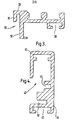
- a so-called shelf support adapter shown in Figure 1 is the basis of the modular system in the sense that the adapter forms or, as in the embodiment of Figure 7, is supported by a counter frame and itself supports either directly or indirectly other extruded sections as illustrated in Figures 2 to 6. It has a main channel 10 intended to fit over a tubular metal frame of square cross-section and is secured in position by a self-tapping screw (not shown) inserted in a hole drilled through a web 8 of the section in a position determined by a centering line 9 extending along the length of the extruded section. The line 9 avoids the need to mark out and centre the position in which holes are to be drilled.
- the main support section also has a shelf support channel 11 on one side of the main channel 10 and, on the other side of the main channel a mounting 12 for other extruded sections intended to overhang the outside of the frame.
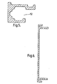
- the mounting 12 has an upstanding lip 13 over which hooks a downwardly projecting lip 21 on the top door track 20 shown in Figure 2 or 31 bottom door track 30 shown in Figure 3, with vertical surfaces 14 on the shelf support adapter and 22 or 32 on appropriate door track in abutment, and so as to align the flat upper surfaces 15 and 23 or 33 thereof.
- the shelf support adapter is provided with a lateral recess 16 which has ridges or teeth 17 extending along the length of each side wall thereof, such that the cross-section of the lateral recess corresponds to the cross-section of a tapped hole having a diameter equal to the width of the recess.
- the recess 16 may have plain walls spaced apart by a distance equal to the diameter of a hole appropriate for receiving a self-tapping screw.
- an upper door track such as shown in Figure 2 is therefore necessaryy only to drill through the vertical wall 22 at intervals along the length thereof as required and where indicated at 24, clearance holes through which screws (not shown) can be inserted and screwed into the lateral recess 16.
- the band moulding 40 of Figure 4 has a smoothly contoured surface 41 presenting an aesthetically pleasing exterior around the counter, and secured to the upper door track 20 by inserting the end 25 thereof in a lateral recess 42.
- Tags (not shown) are slidably inserted in the T-shaped recess 43 extending along the bottom of the moulding, and each has a tapped hole through which a grub-screw or the like is screwed and, passing through a clearance hole drilled where required as indicated at 43, bears upon the end 25 to clamp in the recess 42.
- FIG. 7B Other sections (not illustrated) may be secured to the inside of the band moulding by mounting means including the "screwed" lateral recess 44, similar to the mounting means provided on the shelf support adapter of Figure 1.
- Such other sections may include a support channel for a protective glass screen such as is often required around retail counters (Figure 7B)
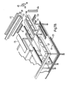
- the retail counter shown exploded in Figure 7, and the schematic cross-section of Figure 7A, is built around four rectangular tubular section frames 70 assembled together by top and bottom corner brackets 71, the bottom corner brackets 71 having integral with supporting legs 72.
- a length C1 of the extruded shelf support adapter section C1 is fitted over the tubular section along each side of the frame 70 at the top and bottom thereof.
- lengths Cl lengths C2 and C3 of upper and lower door tracks as appropriate, are connected as described above with reference to Figures 1 to 3, and lengths of facing moulding C7 are secured in turn to the upper door track sections C2 by the means already described.
- Sliding doors or infill panels are inserted and supported between the sections C2 and C3, as illustrated, which have mitred corners.
- Adjacent lengths C3 are secured together by corner plates 34 received in the ends of the T-shaped groove 35 and clamped there by grub screws.
- the sections C2 need not, however, be secured together at the corners, since sections C7 mounted on the outside edge of the sections C2 are cut-off square and have inserted in the recesses 43 curved corner pieces 45 over which contoured corner blocks 46 are fitted to present a smooth transition between adjacent lengths of band mouldings C7.
- Vertical corners of the counter are finished by mounting there lengths of the corner cover channel section C4, receiving in the internal. recess 52 thereof, he edges of solid infill panels or doors.
- the retail counter shown in Figure 7B is similar to the counter of Figure 7 but in the latter case, the frame is an assembly of square section tubuler sections, the sections being joined together by connecting pieces in a conventional manner as is well known in the art.
- this counter has a glass guard 80 which is held in position against the inner edge of the facing moulding (sections C7) by a further angled section C8 which is secured by a screw (not shown) passing through a clearance hole in the section and entering the screw-fixing channel 44 in the section C7 ( Figure 4).
- FIG. 8 to 11 Various designs of retail counter assembled using the system of the present invention, are shown in Figures 8 to 11 and Figure 11 illustrates how a number of small counter units may be interconnected by means of a counter joining section C5, an enlarged view of which appears in Figure 6.
Landscapes
- Door And Window Frames Mounted To Openings (AREA)
- Assembled Shelves (AREA)
Applications Claiming Priority (2)
| Application Number | Priority Date | Filing Date | Title |
|---|---|---|---|
| GB8316820 | 1983-06-21 | ||
| GB838316820A GB8316820D0 (en) | 1983-06-21 | 1983-06-21 | Extruded sections |
Publications (2)
| Publication Number | Publication Date |
|---|---|
| EP0132059A2 true EP0132059A2 (fr) | 1985-01-23 |
| EP0132059A3 EP0132059A3 (fr) | 1985-08-14 |
Family
ID=10544551
Family Applications (1)
| Application Number | Title | Priority Date | Filing Date |
|---|---|---|---|
| EP84304194A Withdrawn EP0132059A3 (fr) | 1983-06-21 | 1984-06-21 | Profilés extrudés, en particulier pour meubles de magasin |
Country Status (3)
| Country | Link |
|---|---|
| EP (1) | EP0132059A3 (fr) |
| GB (1) | GB8316820D0 (fr) |
| ZA (1) | ZA844722B (fr) |
Cited By (2)
| Publication number | Priority date | Publication date | Assignee | Title |
|---|---|---|---|---|
| GB2199730A (en) * | 1986-12-13 | 1988-07-20 | Fine Art Developments Plc | Display racks |
| GB2344281A (en) * | 1998-11-13 | 2000-06-07 | Pws Distributors Ltd | Self standing frame for mounting fitted type furniture |
Citations (4)
| Publication number | Priority date | Publication date | Assignee | Title |
|---|---|---|---|---|
| US3316041A (en) * | 1964-04-15 | 1967-04-25 | Kewaunee Technical Furniture C | Modular display case |
| FR2161551A5 (fr) * | 1971-11-19 | 1973-07-06 | Marengoni Claudio | |
| US3879096A (en) * | 1973-03-06 | 1975-04-22 | Sheldon & Co E H | Cabinet systems with tension rods as frame members |
| US4148535A (en) * | 1977-03-07 | 1979-04-10 | Litton Business Systems, Inc. | Modular display cases |
-
1983
- 1983-06-21 GB GB838316820A patent/GB8316820D0/en active Pending
-
1984
- 1984-06-21 EP EP84304194A patent/EP0132059A3/fr not_active Withdrawn
- 1984-06-21 ZA ZA844722A patent/ZA844722B/xx unknown
Patent Citations (4)
| Publication number | Priority date | Publication date | Assignee | Title |
|---|---|---|---|---|
| US3316041A (en) * | 1964-04-15 | 1967-04-25 | Kewaunee Technical Furniture C | Modular display case |
| FR2161551A5 (fr) * | 1971-11-19 | 1973-07-06 | Marengoni Claudio | |
| US3879096A (en) * | 1973-03-06 | 1975-04-22 | Sheldon & Co E H | Cabinet systems with tension rods as frame members |
| US4148535A (en) * | 1977-03-07 | 1979-04-10 | Litton Business Systems, Inc. | Modular display cases |
Cited By (3)
| Publication number | Priority date | Publication date | Assignee | Title |
|---|---|---|---|---|
| GB2199730A (en) * | 1986-12-13 | 1988-07-20 | Fine Art Developments Plc | Display racks |
| GB2344281A (en) * | 1998-11-13 | 2000-06-07 | Pws Distributors Ltd | Self standing frame for mounting fitted type furniture |
| GB2344281B (en) * | 1998-11-13 | 2002-11-20 | Pws Distributors Ltd | Self standing fitted type furniture |
Also Published As
| Publication number | Publication date |
|---|---|
| ZA844722B (en) | 1985-02-27 |
| GB8316820D0 (en) | 1983-07-27 |
| EP0132059A3 (fr) | 1985-08-14 |
Similar Documents
| Publication | Publication Date | Title |
|---|---|---|
| US5412912A (en) | Modular slatwall assembly | |
| US5642593A (en) | Knockdown and reassemble office partition | |
| US6167676B1 (en) | Method of connecting partitions | |
| US6295764B1 (en) | Stackable wall panel system | |
| US5040347A (en) | Standardized profiles for window or door frame partitions and method of assembly | |
| US8033059B2 (en) | Paneling system | |
| CA2371520C (fr) | Dispositif d'assemblage de panneaux adjacents | |
| US20030163967A1 (en) | Panel/room divider system | |
| US20080000861A1 (en) | Slatwall adapter | |
| SI9720073A (sl) | Stikalna omara | |
| WO1994000647A2 (fr) | Systeme a elements structuraux modulaires pour dispositifs d'affichage | |
| WO1996039064A1 (fr) | Systeme de rangement pour placard | |
| CA2438430C (fr) | Panneau pour systeme de rangement | |
| EP3453014B1 (fr) | Unité d'affichage | |
| US11606868B2 (en) | Display unit | |
| EP3744306B1 (fr) | Fixation pour meuble de spa | |
| EP0132059A2 (fr) | Profilés extrudés, en particulier pour meubles de magasin | |
| CA2360142A1 (fr) | Structure de cloison | |
| GB2083342A (en) | Frames for fitted furniture | |
| CA1234408A (fr) | Comptoir d'etalage | |
| GB2307263A (en) | Panel sealing structure | |
| US6170211B1 (en) | Demountable wall system | |
| US5090163A (en) | Easily accessible smoke curtain assembly | |
| GB2103752A (en) | Connections to furniture | |
| US6672690B1 (en) | Method of constructing and assembling cupboards and wardrobes |
Legal Events
| Date | Code | Title | Description |
|---|---|---|---|
| PUAI | Public reference made under article 153(3) epc to a published international application that has entered the european phase |
Free format text: ORIGINAL CODE: 0009012 |
|
| AK | Designated contracting states |
Designated state(s): AT BE CH DE FR GB IT LI LU NL SE |
|
| PUAL | Search report despatched |
Free format text: ORIGINAL CODE: 0009013 |
|
| AK | Designated contracting states |
Designated state(s): AT BE CH DE FR GB IT LI LU NL SE |
|
| STAA | Information on the status of an ep patent application or granted ep patent |
Free format text: STATUS: THE APPLICATION IS DEEMED TO BE WITHDRAWN |
|
| 18D | Application deemed to be withdrawn |
Effective date: 19860415 |
|
| RIN1 | Information on inventor provided before grant (corrected) |
Inventor name: PARFITT, ANTHONY DAVID Inventor name: MCKAY, PETER OSWALD DERMON |