EP0132039A2 - Moisture resistant cover for an electroacoustic transducer - Google Patents
Moisture resistant cover for an electroacoustic transducer Download PDFInfo
- Publication number
- EP0132039A2 EP0132039A2 EP84303836A EP84303836A EP0132039A2 EP 0132039 A2 EP0132039 A2 EP 0132039A2 EP 84303836 A EP84303836 A EP 84303836A EP 84303836 A EP84303836 A EP 84303836A EP 0132039 A2 EP0132039 A2 EP 0132039A2
- Authority
- EP
- European Patent Office
- Prior art keywords
- moisture resistant
- layer
- resistant layer
- housing
- assembly
- Prior art date
- Legal status (The legal status is an assumption and is not a legal conclusion. Google has not performed a legal analysis and makes no representation as to the accuracy of the status listed.)
- Withdrawn
Links
Images
Classifications
-
- H—ELECTRICITY
- H04—ELECTRIC COMMUNICATION TECHNIQUE
- H04R—LOUDSPEAKERS, MICROPHONES, GRAMOPHONE PICK-UPS OR LIKE ACOUSTIC ELECTROMECHANICAL TRANSDUCERS; DEAF-AID SETS; PUBLIC ADDRESS SYSTEMS
- H04R1/00—Details of transducers, loudspeakers or microphones
- H04R1/44—Special adaptations for subaqueous use, e.g. for hydrophone
Definitions
- This invention relates to electroacoustic transducers used in wet environments such as lavatory faucets.
- U.S. Patent No. 4,402,095 European Patent Application No. 82300961.8
- Pepper entitled “Ultrasonically Operated Water Faucet” discloses a water faucet that uses an electroacoustic transducer to measure the distance of the hands of the user (or another object) from the faucet outlet in order to control the flow of the water.
- an electroacoustic transducer to measure the distance of the hands of the user (or another object) from the faucet outlet in order to control the flow of the water.
- such a faucet greatly aids in the conservation of water and energy by delivering water only when it is needed.
- the disclosed device can also be used to control the flow of other fluids in appropriate circumstances.
- the electroacoustic transducer of the type used in the preferred embodiment in the above-referenced U.S. Patent comprises essentially a capacitor with a vibratile plate.
- This capacitor is constructed of a thin dielectric film coated with a conductive layer on one side.
- On the other side of the film from the electrically conductive layer is a relatively inflexible grooved plate that forms the other plate of the capacitor.
- the vibratile plate vibrates and produces an acoustical wave. If this wave strikes an object in the vicinity of the transducer, it will be reflected back to the transducer and will cause the vibratile plate to vibrate. With the appropriate voltage applied to the transducer, the vibrating plate will produce an electrical signal in response.
- This type of transducer is also described in greater detail in U.S. Patent Specifications Nos. 4,081,626 and 4,085,297.
- the distance of an object from the transducer can be measured by measuring the time that elapses between the emission of an acoustic wave and the receipt of a reflected wave.
- the range and accuracy of the transducer depend in part on how well a reflected wave can be detected by the vibratile plate.
- a transducer of this type When a transducer of this type is used in a moist environment, such as in a faucet, there is the possibility that water may be splashed on to the transducer and that water droplets may form on the vibratile plate. Since this plate is actually a very thin layer of metal on a thin membrane or film, the weight of the water droplets will change the vibrating characteristics of the plate and adversely affect its sensitivity. The accumulation of water may also reduce the amplitude of the emitted acoustic wave, thereby lowering the amplitude of any reflected wave.
- the ultrasonically operated faucet is used for fluids other than pure water, e.g. fluids with some other substance dissolved or dispersed in them. If droplets of such fluids form on the vibratile plate and the fluid evaporates, a deposit may be left on the plate, thereby permanently degrading its performance. As such deposits build up over time, the transducer will gradually be rendered useless. In addition, if the fluid is corrosive to the metal forming the vibratile plate, the performance of the transducer will also be adversely affected if droplets of the fluid form on the plate.
- the present invention provides an electroacoustical assembly including a housing; and capacitive transducer means, retained in the housing, having a vibratile member, a relatively fixed member and electrical signal terminals for producing an acoustical output signal in a predetermined frequency range in response to an electrical input signal and for producing an electrical output signal in response to the receipt of an acoustical input signal in the predetermined frequency range, the assembly being characterized by a protective cover fastened to the housing including a moisture resistant layer formed of a nonwetting material spaced a predetermined distance from the vibratile member, the predetermined distance being chosen to minimize the attenuation of the acoustical output signal by the moisture resistant layer in the predetermined frequency range.
- An assembly as set forth in the last preceding paragraph may be further characterized in that the protective cover also comprises a relatively rigid screened layer fastened to the housing and supporting the moisture resistant layer, and attachment means for holding the moisture resistant layer in contact with the screened layer.
- the present invention further provides a moisture resistant cover for an electroacoustical transducer assembly of the type including a housing, a vibratile, electrically conductive layer, an electrically nonconductive layer adjacent the electrically conductive layer, a substantially inflexible plate-like member having an electrically conductive surface adjacent the electrically nonconductive layer, means for holding the electrically conductive layer, the electrically nonconductive layer and the plate-like member in the housing, electrical connection means for supplying electrical signals to the electrically conductive layer and the electrically conductive surface, the electrically conductive layer vibrating and producing acoustic waves in response to supplied alternating current electrical signals, the moisture resistant cover being characterized by a moisture resistant layer of material, and means for mounting the moisture resistant layer on the housing and spacing the moisture resistant layer a predetermined distance from the electrically conductive layer where the predetermined distance is substantially equal to an integral multiple of one-half the wavelength of the acoustic waves.
- an assembly as set forth in the last preceding paragraph may be further characterized in that the mounting means comprises a cylindrical side wall attached to the body and to a perforated surface through which the acoustic waves can pass, and by attachment means for holding the moisture resistant layer in contact with the perforated surface.
- An assembly as set forth in any one of the last four immediately preceding paragraphs may be further characterized in that the moisture resistant layer is formed of polytetrafluoroethylene in the form of a woven or nonwoven fabric, a pressed felt or a film.
- an assembly as set forth in any one of the last five immediately preceding paragraphs may be further characterized in that the protective cover includes a cylindrical portion attached to or integral with the screened layer and the attachment means comprises an annular member surrounding the cylindrical portion with a peripheral portion of the moisture resistant layer clamped between the inner surface of the annular member and the outer surface of the cylindrical portion.
- attachment means comprises a bezel member with an opening and an adjacent shoulder portion for retaining the housing, an outer surface and a rearward projecting portion, the moisture resistant layer being fastened to a portion of the bezel member outer surface surrounding the opening; and a spring member engaging the rearward projecting portion and pressing against a rear portion of the housing to urge the screened layer into intimate contact with the moisture resistant layer.
- An assembly as set forth in the last preceding paralaph may be further characterized in that the moisture resistant layer is fastened as aforesaid by adhesive material.
- An assembly as set forth in any one of the last eight immediately preceding paragraphs may be further characterized in that the predetermined distance is approximately one-half a wavelength of the acoustical output signal in the predetermined frequency range.
- the attachment means may further comprise an annular member surrounding the cylindrical side wall with a peripheral portion of the moisture resistant layer compressively retained between the inner surface of the annular member and the outer surface of the cylindrical side wall.
- an electroacoustic transducer having a cover assembly with a moisture resistant layer.
- the moisture resistant layer is preferably made of polytetrafluoroethylene or like material which sheds water and other fluids easily and does not wet easily. It is preferred to use the material of the layer as a woven or nonwoven fabric or a pressed felt.
- the moisture resistant layer is placed at a node of the acoustic wave emitted by the transducer, i.e. either immediately adjacent to the vibratile plate of the transducer or spaced an integral multiple of a half wavelength of the acoustic wave away from the vibratile plate.
- This placement minimizes attenuation of the acoustic wave by the layer, particularly in view of the relative thinness of the layer as compared with the wavelength of the acoustic wave.
- a woven fabric which allows air movement through the fabric, the acoustic waves will pass easily through the fabric.
- the capacitive electroacoustic transducers described above are usually provided with a rigid cover having a screened or perforated surface which serves to protect the delicate vibratile plate while allowing acoustic waves to pass through relatively unimpeded.
- the moisture resistant layer is preferably placed over this cover, either by using an adhesive between the cover and the moisture resistant layer or by mechanical means.
- the use of the aforementioned moisture resistant layer avoids the disadvantages of the prior art.
- the structure of the preferred embodiment also obviates the need for complicated acoustic waveguide structures proposed in the prior art.
- FIGS 1 and 2 show an electroacoustic transducer 10 comprising an insulative housing 12, a conductive, grooved plate 14 and a metallized film 16.
- a metal cover 18 has a rim 20 that is crimped around a flange 22 of the housing 12 to hold the cover in place on the housing. Also, a peripheral edge of the metallized film 16 is clamped between the rim 20 and the flange 22 to hold the film taught.
- a leaf spring 24 retained by housing 12 presses against the back side of the plate 14 to hold it tightly against the film 16.
- the plate 14 and metallized film 16 form a capacitor, and electrical connectors 26 and 28 are provided to make contact with plate 14 and the metallization on the film 16 respectively.
- electrical connectors 26 and 28 are provided to make contact with plate 14 and the metallization on the film 16 respectively.
- an alternating current electrical signal is applied to the electrical connectors, the film 16 will vibrate at the frequency of the electrical signal, thereby producing an acoustic wave of the same frequency.
- a direct current electrical signal is also applied to the electrical connectors, and this d.c. signal constitutes a bias voltage applied to the capacitor to enable the transducer to detect acoustic waves that impinge on the film 16.
- the impinging waves cause the film to vibrate, changing the capacitance of the capacitor at the frequency of the wave and producing an alternating current signal across the electrical connectors.
- the cover 18 has a face portion 30 with a number of perforations 32, forming a screen that provides mechanical protection for the film 16 but allows acoustic waves to pass through.
- the face portion 30 is preferably located at a node of the acoustic waves which the transducer is intended to transmit and detect. This means that the face portion must be either immediately adjacent the film 16 or an integral multiple of a half wavelength of the acoustic wave in air away from the film 16.
- the emitted or detected wave may actually comprise a tone burst including several different frequency waves. In such a case, the node selected would be that of the average wavelength of the different frequency waves.
- a moisture resistant layer 34 is placed over the face portion 30. As shown in Figures 1 and 2, the moisture resistant layer can be held in place by an annular ring 36 which clamps a peripheral portion of the moisture resistant layer between the inner surface of the ring and a cylindrical portion 38 of the cover 18.
- a suitable woven fabric is that which is sold by DuPont under the trademark "Armalon Teflon" fiber fabric.
- the woven fabric is relatively thin compared with the wavelength of the acoustic waves, so it presents negligible attenuation to acoustic waves when placed at a node.
- a woven material has very small gaps between the threads in the weave as compared with the perforations 32, thereby essentially preventing moisture from penetrating the material while at the same time allowing air movement through the material.
- Using a polytetrafluoroethylene material is especially advantageous because such a material is essentially nonwetting, so that even substantial amounts of moisture will not soak into the material. Instead, the material tends to shed almost all moisture.
- polytetrafluoroethylene materials are also believed to be suitable for use as a moisture resistant layer.
- a pressed felt sold by DuPont under the trademark “Armalon Teflon” fiber felt has been found to work satisfactorily.
- a fluorocarbon resin film sold by DuPont under the trademark “Teflon” is also believed to be satisfactory, especially when the film is formed with pores small enough to prevent fluid penetration but such as to allow acoustic waves to pass through the film without undue attenuation.
- FIG. 3 shows an alternative embodiment of the invention.
- an epoxy adhesive is used instead of using a ring 30 to hold the moisture resistant layer to cover 18.
- a thin layer of epoxy resin is applied to the outer surface of face portion 30 and then the moisture resistant layer is mechanically held in place until the epoxy resin cures.
- Great care must be taken when applying the epoxy resin that perforations 32 are not clogged by the resin. It has been found best to use a relatively hard roller or brayer to apply the epoxy resin to the face portion without filling the perforations.
- FIG. 4 shows another alternative embodiment of the invention.
- the moisture resistant layer 34 is adhesively bonded to a bezel 40, preferably using an epoxy resin as the adhesive.
- the bezel has a circular opening 42 through which the transducer 10 protrudes.
- the rim 20 rests against a shoulder portion 44 of the bezel, and the transducer is retained in the bezel by a leaf spring 46 which bears against a back portion of the housing 12.
- the leaf spring 46 is retained by a rearward projecting portion of the bezel and also forces the transducer against the moisture resistant layer 34 to keep this layer taught.
Abstract
A capacitive type electroacoustic transducer is provided with a moisture resistant layer (34) to allow use of the transducer in wet environments. The moisture resistant layer is fastened over a protective cover (18) and is located at a node of the acoustic waves emitted by the transducer. A woven polytetrafluoroethylene material is preferably used for the moisture resistant properties as well as minimum attenuation of the acoustic waves.
Description
- This invention relates to electroacoustic transducers used in wet environments such as lavatory faucets.
- U.S. Patent No. 4,402,095 (European Patent Application No. 82300961.8) to Robert B. Pepper entitled "Ultrasonically Operated Water Faucet" discloses a water faucet that uses an electroacoustic transducer to measure the distance of the hands of the user (or another object) from the faucet outlet in order to control the flow of the water. As described in further detail in that U.S. Patent, such a faucet greatly aids in the conservation of water and energy by delivering water only when it is needed. The disclosed device can also be used to control the flow of other fluids in appropriate circumstances.
- The electroacoustic transducer of the type used in the preferred embodiment in the above-referenced U.S. Patent comprises essentially a capacitor with a vibratile plate. This capacitor is constructed of a thin dielectric film coated with a conductive layer on one side. On the other side of the film from the electrically conductive layer is a relatively inflexible grooved plate that forms the other plate of the capacitor. When an appropriate electrical signal is applied to the capacitor, the vibratile plate vibrates and produces an acoustical wave. If this wave strikes an object in the vicinity of the transducer, it will be reflected back to the transducer and will cause the vibratile plate to vibrate. With the appropriate voltage applied to the transducer, the vibrating plate will produce an electrical signal in response. This type of transducer is also described in greater detail in U.S. Patent Specifications Nos. 4,081,626 and 4,085,297.
- The distance of an object from the transducer can be measured by measuring the time that elapses between the emission of an acoustic wave and the receipt of a reflected wave. The range and accuracy of the transducer depend in part on how well a reflected wave can be detected by the vibratile plate.
- When a transducer of this type is used in a moist environment, such as in a faucet, there is the possibility that water may be splashed on to the transducer and that water droplets may form on the vibratile plate. Since this plate is actually a very thin layer of metal on a thin membrane or film, the weight of the water droplets will change the vibrating characteristics of the plate and adversely affect its sensitivity. The accumulation of water may also reduce the amplitude of the emitted acoustic wave, thereby lowering the amplitude of any reflected wave.
- Further difficulty may occur if the ultrasonically operated faucet is used for fluids other than pure water, e.g. fluids with some other substance dissolved or dispersed in them. If droplets of such fluids form on the vibratile plate and the fluid evaporates, a deposit may be left on the plate, thereby permanently degrading its performance. As such deposits build up over time, the transducer will gradually be rendered useless. In addition, if the fluid is corrosive to the metal forming the vibratile plate, the performance of the transducer will also be adversely affected if droplets of the fluid form on the plate.
- One prior art proposal for protecting a piezoelectric resonator, a different kind of electroacoustical transducer, from excessive moisture is a foam rubber plug located in an acoustical waveguide between the transducer and the object to be detected. This proposal is described in German Offen- legungsschrift No. 2,057,150 published 25 May 1972. One of the major difficulties with such a proposal is that foam will absorb water in the foam cells. Such absorbed water would undesirably attenuate an acoustic wave emitted by or to be detected by the capacitive type of electroacoustical transducer. It has also been proposed in the same publication to use a resonant window in place of the foam rubber plug described above; however, such a window has the disadvantage that it also attenuates the acoustic waves passing through it. Furthermore, the acoustic waveguides in the aforementioned proposal make the transducers unacceptably bulky for many applications and add extra cost to the transducer assembly.
- The present invention provides an electroacoustical assembly including a housing; and capacitive transducer means, retained in the housing, having a vibratile member, a relatively fixed member and electrical signal terminals for producing an acoustical output signal in a predetermined frequency range in response to an electrical input signal and for producing an electrical output signal in response to the receipt of an acoustical input signal in the predetermined frequency range, the assembly being characterized by a protective cover fastened to the housing including a moisture resistant layer formed of a nonwetting material spaced a predetermined distance from the vibratile member, the predetermined distance being chosen to minimize the attenuation of the acoustical output signal by the moisture resistant layer in the predetermined frequency range.
- An assembly as set forth in the last preceding paragraph may be further characterized in that the protective cover also comprises a relatively rigid screened layer fastened to the housing and supporting the moisture resistant layer, and attachment means for holding the moisture resistant layer in contact with the screened layer.
- The present invention further provides a moisture resistant cover for an electroacoustical transducer assembly of the type including a housing, a vibratile, electrically conductive layer, an electrically nonconductive layer adjacent the electrically conductive layer, a substantially inflexible plate-like member having an electrically conductive surface adjacent the electrically nonconductive layer, means for holding the electrically conductive layer, the electrically nonconductive layer and the plate-like member in the housing, electrical connection means for supplying electrical signals to the electrically conductive layer and the electrically conductive surface, the electrically conductive layer vibrating and producing acoustic waves in response to supplied alternating current electrical signals, the moisture resistant cover being characterized by a moisture resistant layer of material, and means for mounting the moisture resistant layer on the housing and spacing the moisture resistant layer a predetermined distance from the electrically conductive layer where the predetermined distance is substantially equal to an integral multiple of one-half the wavelength of the acoustic waves.
- An assembly as set forth in the last preceding paragraph may be further characterized in that the mounting means comprises a cylindrical side wall attached to the body and to a perforated surface through which the acoustic waves can pass, and by attachment means for holding the moisture resistant layer in contact with the perforated surface.
- An assembly as set forth in any one of the last four immediately preceding paragraphs may be further characterized in that the moisture resistant layer is formed of polytetrafluoroethylene in the form of a woven or nonwoven fabric, a pressed felt or a film.
- An assembly as set forth in any one of the last five immediately preceding paragraphs may be further characterized in that the protective cover includes a cylindrical portion attached to or integral with the screened layer and the attachment means comprises an annular member surrounding the cylindrical portion with a peripheral portion of the moisture resistant layer clamped between the inner surface of the annular member and the outer surface of the cylindrical portion.
- An assembly as set forth in any one of the last five immediately preceding paragraphs but one may be further characterized in that the attachment means comprises a bezel member with an opening and an adjacent shoulder portion for retaining the housing, an outer surface and a rearward projecting portion, the moisture resistant layer being fastened to a portion of the bezel member outer surface surrounding the opening; and a spring member engaging the rearward projecting portion and pressing against a rear portion of the housing to urge the screened layer into intimate contact with the moisture resistant layer.
- An assembly as set forth in the last preceding paralaph may be further characterized in that the moisture resistant layer is fastened as aforesaid by adhesive material.
- An assembly as set forth in any one of the last eight immediately preceding paragraphs may be further characterized in that the predetermined distance is approximately one-half a wavelength of the acoustical output signal in the predetermined frequency range.
- The attachment means may further comprise an annular member surrounding the cylindrical side wall with a peripheral portion of the moisture resistant layer compressively retained between the inner surface of the annular member and the outer surface of the cylindrical side wall.
- In accordance with the preferred embodiment of the present invention, an electroacoustic transducer is disclosed having a cover assembly with a moisture resistant layer. The moisture resistant layer is preferably made of polytetrafluoroethylene or like material which sheds water and other fluids easily and does not wet easily. It is preferred to use the material of the layer as a woven or nonwoven fabric or a pressed felt. The moisture resistant layer is placed at a node of the acoustic wave emitted by the transducer, i.e. either immediately adjacent to the vibratile plate of the transducer or spaced an integral multiple of a half wavelength of the acoustic wave away from the vibratile plate. This placement minimizes attenuation of the acoustic wave by the layer, particularly in view of the relative thinness of the layer as compared with the wavelength of the acoustic wave. In addition, by using a woven fabric which allows air movement through the fabric, the acoustic waves will pass easily through the fabric.
- The capacitive electroacoustic transducers described above are usually provided with a rigid cover having a screened or perforated surface which serves to protect the delicate vibratile plate while allowing acoustic waves to pass through relatively unimpeded. The moisture resistant layer is preferably placed over this cover, either by using an adhesive between the cover and the moisture resistant layer or by mechanical means.
- The use of the aforementioned moisture resistant layer avoids the disadvantages of the prior art. The placement of the moisture resistant layer, as well as the material preferably used for it, minimize attenuation of acoustic waves emitted or detected by the electroacoustic transducer. The structure of the preferred embodiment also obviates the need for complicated acoustic waveguide structures proposed in the prior art.
- There now follows a detailed description with is to be read with reference to the accompanying drawings of an assembly according to the invention; it is to be clearly understood that this assembly has been selected for description to illustrate the invention by way of example and not by way of limitation.
- In the accompanying drawings
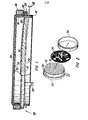
- Figure 1 shows a partial cut-away view of of an electroacoustic transducer with a moisture resistant layer attached to it;
- Figure 2 shows an exploded view of the device of Figure 1=
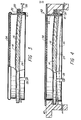
- Figure 3 shows a partial cut-away view of an alternative embodiment of the device shown in Figure 1; and
- Figure 4 shows a partial cut-away view of another alternative embodiment of the device shown in Figure 1.
- As mentioned above, the structure and operation of a capacitive type electroacoustic transducer used in the preferred embodiment of the present invention is described in detail in U.S. Patents Nos. 4,081,626 and 4,085,297.
- Figures 1 and 2 show an
electroacoustic transducer 10 comprising aninsulative housing 12, a conductive,grooved plate 14 and ametallized film 16. Ametal cover 18 has arim 20 that is crimped around aflange 22 of thehousing 12 to hold the cover in place on the housing. Also, a peripheral edge of themetallized film 16 is clamped between therim 20 and theflange 22 to hold the film taught. Aleaf spring 24 retained byhousing 12 presses against the back side of theplate 14 to hold it tightly against thefilm 16. - The
plate 14 andmetallized film 16 form a capacitor, andelectrical connectors plate 14 and the metallization on thefilm 16 respectively. When an alternating current electrical signal is applied to the electrical connectors, thefilm 16 will vibrate at the frequency of the electrical signal, thereby producing an acoustic wave of the same frequency. A direct current electrical signal is also applied to the electrical connectors, and this d.c. signal constitutes a bias voltage applied to the capacitor to enable the transducer to detect acoustic waves that impinge on thefilm 16. The impinging waves cause the film to vibrate, changing the capacitance of the capacitor at the frequency of the wave and producing an alternating current signal across the electrical connectors. - The
cover 18 has aface portion 30 with a number ofperforations 32, forming a screen that provides mechanical protection for thefilm 16 but allows acoustic waves to pass through. Theface portion 30 is preferably located at a node of the acoustic waves which the transducer is intended to transmit and detect. This means that the face portion must be either immediately adjacent thefilm 16 or an integral multiple of a half wavelength of the acoustic wave in air away from thefilm 16. In some applications the emitted or detected wave may actually comprise a tone burst including several different frequency waves. In such a case, the node selected would be that of the average wavelength of the different frequency waves. - When the
electroacoustic transducer 10 is used in a wet environment, such as on a faucet, there is the possibility that moisture will get on thefilm 16 and degrade the performance of the transducer. In order to prevent moisture from passing through theperforations 32, a moistureresistant layer 34 is placed over theface portion 30. As shown in Figures 1 and 2, the moisture resistant layer can be held in place by anannular ring 36 which clamps a peripheral portion of the moisture resistant layer between the inner surface of the ring and acylindrical portion 38 of thecover 18. - It has been found advantageous to make the moisture resistant layer out of a woven or nonwoven fabric made of polytetrafluoroethylene. A suitable woven fabric is that which is sold by DuPont under the trademark "Armalon Teflon" fiber fabric. The woven fabric is relatively thin compared with the wavelength of the acoustic waves, so it presents negligible attenuation to acoustic waves when placed at a node. A woven material has very small gaps between the threads in the weave as compared with the
perforations 32, thereby essentially preventing moisture from penetrating the material while at the same time allowing air movement through the material. Using a polytetrafluoroethylene material is especially advantageous because such a material is essentially nonwetting, so that even substantial amounts of moisture will not soak into the material. Instead, the material tends to shed almost all moisture. - Other polytetrafluoroethylene materials are also believed to be suitable for use as a moisture resistant layer. In particular, a pressed felt sold by DuPont under the trademark "Armalon Teflon" fiber felt has been found to work satisfactorily. A fluorocarbon resin film sold by DuPont under the trademark "Teflon" is also believed to be satisfactory, especially when the film is formed with pores small enough to prevent fluid penetration but such as to allow acoustic waves to pass through the film without undue attenuation.
- Figure 3 shows an alternative embodiment of the invention. Instead of using a
ring 30 to hold the moisture resistant layer to cover 18, an epoxy adhesive is used. A thin layer of epoxy resin is applied to the outer surface offace portion 30 and then the moisture resistant layer is mechanically held in place until the epoxy resin cures. Great care must be taken when applying the epoxy resin that perforations 32 are not clogged by the resin. It has been found best to use a relatively hard roller or brayer to apply the epoxy resin to the face portion without filling the perforations. - Figure 4 shows another alternative embodiment of the invention. In this embodiment the moisture
resistant layer 34 is adhesively bonded to a bezel 40, preferably using an epoxy resin as the adhesive. The bezel has acircular opening 42 through which thetransducer 10 protrudes. Therim 20 rests against ashoulder portion 44 of the bezel, and the transducer is retained in the bezel by aleaf spring 46 which bears against a back portion of thehousing 12. Theleaf spring 46 is retained by a rearward projecting portion of the bezel and also forces the transducer against the moistureresistant layer 34 to keep this layer taught. - It will be understood that, while the preferred embodiments for attaching the disclosed moisture resistant layer to
transducer 10 have been described above, other means are possible without departing from the spirit of the invention. Likewise, the preferred materials for the moisture resistant layer have been disclosed; however, there may be other materials that will also be suitable for use. It is important to select a material that will present minimum attenuation to acoustic waves, will impede or prevent the penetration of moisture and will not wet or absorb moisture.
Claims (10)
1. An electroacoustical transducer assembly including a housing (12); and capacitive transducer means (14,16), retained in the housing, having a vibratile member (16), a relatively fixed member (14) and electrical signal terminals (28) for producing an acoustical output signal in a predetermined frequency range in response to an electrical input signal and for producing an electrical output signal in response to the receipt of an acoustical input signal in the predetermined frequency range, the assembly being characterized by a protective cover fastened to the housing (12) including a moisture resistant layer (34) formed of a nonwetting material, spaced a predetermined distance being chosen to minimize the attenuation of the acoustical output signal by the moisture resistant layer in the predetermined frequency range.
2. An assembly according to claim 1 further characterized in that the protective cover also comprises a relatively rigid screened layer (30) fastened to the housing and supporting the moisture resistant layer, and attachment means (36) for holding the moisture resistant layer in contact with the screened layer.
3. A moisture resistant cover for an electroacoustical transducer assembly of the type including, a housing (12), a vibratile, electrically conductive layer (16), an electrically nonconductive layer adjacent the electrically conductive layer, a substantially inflexible plate-like member (14) having an electrically conductive surface adjacent the electrically nonconductive layer, means (26) for holding the electrically conductive layer, the electrically nonconductive layer and the plate-like member in the housing, electrical connection means (28) for supplying elect- electrically conductive surface, the electrically conductive layer vibrating and producing acoustic waves in response to supplied alternating current electrical signals, the moisture resistant cover being characterized by a moisture resistant layer of material (34), and means (36) for mounting the moisture resistant layer on the housing and spacing the moisture resistant layer a predetermined distance from the electrically conductive layer where the predetermined distance is substantially equal to an integral multiple of one-half the wavelength of the acoustic waves.
4. A moisture resistant cover according to claim 3 further characterized in that the mounting means (36) comprises a cylindrical side wall (38) attached to the body and to a perforated surface (30) through which the acoustic waves can pass, and attachment means (36) for holding the moisture resistant layer in contact with the perforated surface.
5. An assembly/cover according to any one of the preceding claims further characterized in that the moisture resistant layer is formed of polytetrafluoroethylene in the form of a woven or nonwoven fabric, a pressed felt or a film.
6. An assembly/cover according to any one of the preceding claims further characterized in that the protective cover includes a cylindrical portion (38) attached to or integral with the screened layer and the attachment means comprises an annular member (36) surrounding the cylindrical portion with a peripheral portion of the moisture resistant layer clamped between the inner surface of the annular member and the outer surface of the cylindrical portion.
7. An assembly/cover according to any of claims 1 to 5 further characterized in that the attachment means comprises a bezel member (40) with an opening (42) and an adjacent shoulder portion (44) for retaining the housing, an outer surface and a rearward projecting portion, the moisture resistant layer being fastened to a portion of the bezel member outer surface surrounding the opening; and a spring member (46) engaging the rearward projecting portion and pressing against a rear portion of the housing to urge the screened layer into intimate contact with the moisture resistant layer (34).
8. An assembly/cover according to claim 7 further characterized in that the moisture resistant layer is fastened as aforesaid by adhesive material.
9. An assembly according to any one of the preceeding claims further characterized in that the predetermined distance is approximately one-half a wavelength of the acoustical output signal in the predetermined frequency range.
10. A moisture resistant cover according to any one of claims 3 to 5 and 7 to 9 further characterized in that the attachment means comprises an annular member (36) surrounding the cylindrical side wall with a peripheral portion of the moisture resistant layer compressively retained between the inner surface of the annular member and the outer surface of the cylindrical side wall.
Applications Claiming Priority (2)
| Application Number | Priority Date | Filing Date | Title |
|---|---|---|---|
| US50277083A | 1983-06-09 | 1983-06-09 | |
| US502770 | 1983-06-09 |
Publications (2)
| Publication Number | Publication Date |
|---|---|
| EP0132039A2 true EP0132039A2 (en) | 1985-01-23 |
| EP0132039A3 EP0132039A3 (en) | 1986-07-23 |
Family
ID=23999340
Family Applications (1)
| Application Number | Title | Priority Date | Filing Date |
|---|---|---|---|
| EP84303836A Withdrawn EP0132039A3 (en) | 1983-06-09 | 1984-06-06 | Moisture resistant cover for an electroacoustic transducer |
Country Status (1)
| Country | Link |
|---|---|
| EP (1) | EP0132039A3 (en) |
Cited By (3)
| Publication number | Priority date | Publication date | Assignee | Title |
|---|---|---|---|---|
| EP0154256A2 (en) * | 1984-03-08 | 1985-09-11 | Polaroid Corporation | Ultrasonic transducer for use in a corrosive/abrasive environment |
| FR2683969A1 (en) * | 1991-11-15 | 1993-05-21 | Thomson Csf | SEALING MEMBRANE FOR UNDERWATER DEVICE, PARTICULARLY FOR UNDERWATER ACOUSTIC DEVICE, AND DEVICE COMPRISING SUCH A MEMBRANE. |
| WO1995021512A1 (en) * | 1994-02-03 | 1995-08-10 | Knowles Electronics, Inc. | Water submersible microphone |
Citations (6)
| Publication number | Priority date | Publication date | Assignee | Title |
|---|---|---|---|---|
| US3311703A (en) * | 1963-05-21 | 1967-03-28 | Carl E Grinstead | Microphone with low frequency filter |
| US3944756A (en) * | 1975-03-05 | 1976-03-16 | Electro-Voice, Incorporated | Electret microphone |
| US4081626A (en) * | 1976-11-12 | 1978-03-28 | Polaroid Corporation | Electrostatic transducer having narrowed directional characteristic |
| GB2015299A (en) * | 1978-02-20 | 1979-09-05 | Hosiden Electronics Co | Electret microphone |
| GB1559214A (en) * | 1977-12-20 | 1980-01-16 | Brown Communications Ltd Sg | Protection of devices against immersion |
| GB2064263A (en) * | 1979-11-30 | 1981-06-10 | Pye Electronic Prod Ltd | Microphone unit |
-
1984
- 1984-06-06 EP EP84303836A patent/EP0132039A3/en not_active Withdrawn
Patent Citations (6)
| Publication number | Priority date | Publication date | Assignee | Title |
|---|---|---|---|---|
| US3311703A (en) * | 1963-05-21 | 1967-03-28 | Carl E Grinstead | Microphone with low frequency filter |
| US3944756A (en) * | 1975-03-05 | 1976-03-16 | Electro-Voice, Incorporated | Electret microphone |
| US4081626A (en) * | 1976-11-12 | 1978-03-28 | Polaroid Corporation | Electrostatic transducer having narrowed directional characteristic |
| GB1559214A (en) * | 1977-12-20 | 1980-01-16 | Brown Communications Ltd Sg | Protection of devices against immersion |
| GB2015299A (en) * | 1978-02-20 | 1979-09-05 | Hosiden Electronics Co | Electret microphone |
| GB2064263A (en) * | 1979-11-30 | 1981-06-10 | Pye Electronic Prod Ltd | Microphone unit |
Cited By (5)
| Publication number | Priority date | Publication date | Assignee | Title |
|---|---|---|---|---|
| EP0154256A2 (en) * | 1984-03-08 | 1985-09-11 | Polaroid Corporation | Ultrasonic transducer for use in a corrosive/abrasive environment |
| EP0154256B1 (en) * | 1984-03-08 | 1990-07-18 | Polaroid Corporation | Ultrasonic transducer for use in a corrosive/abrasive environment |
| FR2683969A1 (en) * | 1991-11-15 | 1993-05-21 | Thomson Csf | SEALING MEMBRANE FOR UNDERWATER DEVICE, PARTICULARLY FOR UNDERWATER ACOUSTIC DEVICE, AND DEVICE COMPRISING SUCH A MEMBRANE. |
| WO1993010644A1 (en) * | 1991-11-15 | 1993-05-27 | Thomson-Csf | Watertight membrane for underwater acoustic device |
| WO1995021512A1 (en) * | 1994-02-03 | 1995-08-10 | Knowles Electronics, Inc. | Water submersible microphone |
Also Published As
| Publication number | Publication date |
|---|---|
| EP0132039A3 (en) | 1986-07-23 |
Similar Documents
| Publication | Publication Date | Title |
|---|---|---|
| US5646470A (en) | Acoustic transducer | |
| US4156800A (en) | Piezoelectric transducer | |
| US3255431A (en) | Hydrophone | |
| US4607186A (en) | Ultrasonic transducer with a piezoelectric element | |
| CA1274619A (en) | Ultrasonic transducer for use in a corrosive/abrasive environment | |
| EP0237616A2 (en) | Line array transducer assembly | |
| MXPA97000089A (en) | Systems of acceleration sensitivity microphone in site reduc | |
| JP2005057775A (en) | Electret condenser microphone | |
| KR20010039800A (en) | Piezoelectric Electro-Acoustic Transducer | |
| US3849679A (en) | Electroacoustic transducer with controlled beam pattern | |
| US5185728A (en) | Omnidirectional ultrasonic transducer | |
| US4864179A (en) | Two-dimensional piezoelectric transducer assembly | |
| GB2029160A (en) | Electroacoustic vibration assemblies and transducers | |
| CA1087286A (en) | Electromagnetic radiation detector with large area sensing medium | |
| US4458170A (en) | Ultrasonic transmitter-receiver | |
| EP0181506B1 (en) | Flexible piezoelectric transducer assembly | |
| EP0132039A2 (en) | Moisture resistant cover for an electroacoustic transducer | |
| US4151378A (en) | Electrostatic microphone with damping to improve omnidirectionality, flatten frequency response, reduce wind noise | |
| GB2110901A (en) | Electronstatic transducer | |
| WO2002009471A1 (en) | Aerial ultrasonic sensor | |
| CA1180100A (en) | Ultrasonic transmitter-receiver | |
| US20050215907A1 (en) | Ultrasonic transducer for electronic devices | |
| US3253674A (en) | Ceramic microphone | |
| US5436874A (en) | Method and apparatus for sensing acoustic signals in a liquid | |
| RU2273967C1 (en) | Electroacoustic transducer |
Legal Events
| Date | Code | Title | Description |
|---|---|---|---|
| PUAI | Public reference made under article 153(3) epc to a published international application that has entered the european phase |
Free format text: ORIGINAL CODE: 0009012 |
|
| AK | Designated contracting states |
Designated state(s): AT BE CH DE FR GB IT LI LU NL SE |
|
| 17P | Request for examination filed |
Effective date: 19850722 |
|
| PUAL | Search report despatched |
Free format text: ORIGINAL CODE: 0009013 |
|
| AK | Designated contracting states |
Kind code of ref document: A3 Designated state(s): AT BE CH DE FR GB IT LI LU NL SE |
|
| STAA | Information on the status of an ep patent application or granted ep patent |
Free format text: STATUS: THE APPLICATION IS DEEMED TO BE WITHDRAWN |
|
| 18D | Application deemed to be withdrawn |
Effective date: 19870124 |