EP0131817B1 - Adaptives differentielles PCM-System mit durch Residuum gesteuerter Anpassung des Rückkopplungsprädiktors - Google Patents
Adaptives differentielles PCM-System mit durch Residuum gesteuerter Anpassung des Rückkopplungsprädiktors Download PDFInfo
- Publication number
- EP0131817B1 EP0131817B1 EP19840107530 EP84107530A EP0131817B1 EP 0131817 B1 EP0131817 B1 EP 0131817B1 EP 19840107530 EP19840107530 EP 19840107530 EP 84107530 A EP84107530 A EP 84107530A EP 0131817 B1 EP0131817 B1 EP 0131817B1
- Authority
- EP
- European Patent Office
- Prior art keywords
- predictor
- signal
- receiver
- coefficients
- transmitter
- Prior art date
- Legal status (The legal status is an assumption and is not a legal conclusion. Google has not performed a legal analysis and makes no representation as to the accuracy of the status listed.)
- Expired
Links
- 230000003044 adaptive effect Effects 0.000 title claims description 19
- 230000006978 adaptation Effects 0.000 title claims description 11
- 238000012886 linear function Methods 0.000 claims description 10
- 230000001419 dependent effect Effects 0.000 claims description 9
- 230000005540 biological transmission Effects 0.000 description 6
- 230000000694 effects Effects 0.000 description 3
- 230000003247 decreasing effect Effects 0.000 description 2
- 230000009977 dual effect Effects 0.000 description 2
- 230000007246 mechanism Effects 0.000 description 2
- 230000004044 response Effects 0.000 description 2
- 230000002238 attenuated effect Effects 0.000 description 1
- 230000008859 change Effects 0.000 description 1
- 230000010355 oscillation Effects 0.000 description 1
- ZMRUPTIKESYGQW-UHFFFAOYSA-N propranolol hydrochloride Chemical compound [H+].[Cl-].C1=CC=C2C(OCC(O)CNC(C)C)=CC=CC2=C1 ZMRUPTIKESYGQW-UHFFFAOYSA-N 0.000 description 1
- 230000011664 signaling Effects 0.000 description 1
Images


Classifications
-
- H—ELECTRICITY
- H03—ELECTRONIC CIRCUITRY
- H03M—CODING; DECODING; CODE CONVERSION IN GENERAL
- H03M3/00—Conversion of analogue values to or from differential modulation
- H03M3/04—Differential modulation with several bits, e.g. differential pulse code modulation [DPCM]
- H03M3/042—Differential modulation with several bits, e.g. differential pulse code modulation [DPCM] with adaptable step size, e.g. adaptive differential pulse code modulation [ADPCM]
Definitions
- the invention relates to adaptive differential pulse code modulation systems with residual adaptation of feedback predictor and in particular such systems having adaptive prediction coefficients.
- the invention is particularly concerned with adaptive differential pulse code modulation (ADPCM) systems of the kind exemplified as prior art in U.S. Patent No. 4,317,208, issued February 23, 1982 to Takashi Areski, to which the reader is directed for reference.
- ADPCM adaptive differential pulse code modulation
- Such systems include a transmitter in which a subtractor provides the difference between the instant signal sample and a prediction signal derived from one or more earlier samples. The difference signal is then quantized and transmitted.
- the receiver includes an inverse quantizer and a predictor which reconstruct the signal from the received difference or residual signal.
- the quantizers will be adaptive so as to vary the step size, or transfer function slope, according to the magnitude of the input difference signal. This better utilizes the dynamic range of the quantizer and improves response to low amplitude signals.
- each predictor may be adaptive, i.e. its coefficients change with time, to better follow the variations with time of the signal to be predicted, and to optimize performance with different types of signal, for example voice, voiceband data.
- the predictor transfer function is adapted to the time varying input signal so that, ideally, the energy in the difference or residual signal is minimized at all times.
- the values of the predictor coefficients are not transmitted explicitly to the receiver, but are derived from the quantized difference siganl in an identical manner in both the transmitter and the receiver.
- One type of predictor known as "pole-based" uses a feedback loop and derives its coefficients according to the equation:- where g is a small positive value and F 1 and F 2 are nondecreasing functions.
- g is a small positive value and F 1 and F 2 are nondecreasing functions.
- F 1 and F 2 are nondecreasing functions.
- the coefficients of the receiver differ from those of the transmitter if transmission errors occur. This is because the prediction coefficients in the receiver are derived from the received difference signal. Errors in this signal cause the receiver prediction coefficients to depart from those in the transmitter. The difference or mistracking may persist even when the errors have ceased.
- Araseki proposes overcoming the stability problem by using a zero-based predictor, i.e. which does not have a feedback loop.
- zero-based predictors are not susceptible to instability, they do suffer from the disadvantage that they provide less prediction gain for speech and like signals then pole-based predictors.
- the predictor adaptation driven via the feedback loop by the predictor output signal may have multiple stable states.
- the receiver may stabilize with its predictor coefficients at values different from those of the transmitter. It transfer function, which is normally the inverse of that of the transmitter, will have a distorted frequency response, so one tone will be attenuated and the other amplified, possibly to an extent that the inequality is unacceptable.
- pole-based predictors overcome the problems of instability and mistracking, but suffer from low predictor gain.
- Pole-based predictors can be made stable by applying a stability check, but hitherto have suffered from mistracking.
- the present invention provides a transmitter for transmitting an adaptive differential pulse code modulated signal, including; a subtractor for deriving the difference E j between an input signal X j and a predicted value X ⁇ j , a quantizer for quantizing the difference signal E j from said subtractor to obtain a numeric representation N j thereof;
- the present invention further provides a receiver for receiving an adaptive differential pulse code modulated signal, comprising:
- predictor means having variable prediction coefficients, for receiving said reconstructed signal and providing therefrom a predictor output X j p constituting at least part of said predicted value X ⁇ j ; characterized in that said predictor means is adapted to derive each predictor coefficient as a non-linear function dependent upon a finite number of past values of the difference signal or residual ⁇ j and not directly dependent on the reconstructed signal X j .
- the non-linear function may be derived also from the immediate past coefficient values of one or more lower numbered predictor coefficients. Generally, the higher the number of the coefficient, the earlier the past value to which it corresponds. Thus the first or lowest predictor coefficient will not be a non-linear function of any past coefficient value.
- the two predictor coefficients A 1 and A 2 are derived in accordance with the equations:- where
- the aforementioned embodiments of the invention may be used alone or with an additional predictor not employing feedback (zero-based).
- an additional predictor it may also be preferable to derive the prediction coefficients for the pole-based predictor not only from the difference signal, but also from the output of the zero-based predictor, i.e. from the partially reconstructed input signal.
- a conventional adaptive differential pulse code modulation system with adaptive prediction comprises a transmitter 10 and a receiver 12.
- a digital signal to be transmitted is applied to an input terminal 14 of the transmitter 10.
- the signal is represented as X j , signifying it is applied at time point or sample period j.
- the input terminal 14 is connected to a subtractor 16, which provides a difference signal E j obtained by subtracting from the input signal X j a predicted signal X j , being the output X ⁇ jp of a pole-based predictor 18.
- the difference signal E j is quantized by a quantizer 20 to provide a corresponding numeric representation N j at transmitter output terminal 22 for transmission to the receiver 12.
- the quantizer 20 will be adaptive i.e. its step size or transfer function will vary according to the input signal magnitude. Such quantizers are known and so will not be described in detail here. It should be noted that although an adaptive quantizer is preferred, a fixed quantizer might be used instead.
- the numerical representation N j is also applied to an inverse quantizer 24 which regenerates the difference signal E j .
- the characteristics of the inverse quantizer 24 must match those of the quantizer 20, and so will be adaptive if quantizer 20 is adaptive.
- An adder 26 sums the regenerated difference signal E j with the predictor output signal X ⁇ jp , constituting the predicted value X ⁇ j , to provide a reconstructed input signal X' j at the input of predictor 18.
- the pole-based predictor 18 has a feedback loop 28 which applies the predictor output X ⁇ jp to the adder 26.
- the predictor 18 derives the signal X ⁇ jp using the past input signal values in accordance with the equations:-
- a 1 -An are prediction coefficients.
- the predictor coefficients are adaptively corrected, as signified by arrow 30, in dependence upon the regenerated difference sinal ⁇ j , as signified by the broken line 32, and upon the previously reconstructed input signal X' j , as signified by the broken line 34. More specifically, the coefficients A
- the receiver 12 comprises an inverse quantizer 124, and a pole-based predictor 118, corresponding to inverse quantizer 24 and predictor 18 in the transmitter 10.
- the receiver inverse quantizer 124 receives the numerical representation N j from the transmitter 10 and produces therefrom the regenerated difference signal ⁇ j .
- An adder 126 sums the predicted signal X j , constituted by the output signal X j p from the predictor 118, with the difference signal to produce the reconstructed input signal X j at the output terminal 122 of the receiver 12. This signal X j is also applied to the input predictor 118.
- the coefficients of receiver predictor 118 are adaptively corrected in like manner to those of the transmitter predictor 18 as indicated by corresponding broken lines 132 and 134.
- the receiver 12 operates in the inverse manner to the transmitter 10 and will faithfully reconstruct the original signal so long as the predictor coefficients are the same in both predictors 18 and 118 at any instant in time.
- the receiver and transmitter are then said to be "tracking".
- errors will occur in the transmission between the transmitter and the receiver. These errors will result in differences between the prediction coefficients of the predictors 18 and 118 so the receiver output will no longer faithfully reproduce the original signal.
- the coefficients in the receiver will realign with those in the transmitter.
- the mechanisms whereby this is achieved are stability checks which restrict the range of the predictor and the leakage factor (1-5) so that they will converge. There is a limit to the extent to which these mechanisms can be applied whilst assuring adequate predictor performance.
- the problem is overcome by not using the reconstructed input signal X' j , X j to adjust the predictor coefficients.
- Figure 2 which illustrates a first embodiment of the invention
- the component parts of the transmitter 10A and receiver 12A are the same as those illustrated in Figure 1 and so for ease of description corresponding parts are identified by the same reference numeral. It should be noted, however, that in Figure 2 there are no broken lines corresponding to lines 34 and 134 in Figure 1. This is because the prediction coefficients are no longer dependent upon X' j , X ; , the reconstructed input signal.
- the predictor coefficients are derived in accordance with the general equation:- where i is the number of the coefficient from 1 to n, the higher numbers corresponding to earlier time values.
- the first term is a linear decay term to allow effects of transmission errors to die away
- the second term is the adaptation term.
- the 6 1 constant might be omitted in some ADPCM system applications.
- g 1 and g 2 are chosen depending upon the characteristics of the signal and those specified are typically suitable for speech. Other values may be used providing the ratios of ⁇ 1 :g 1 , and ⁇ 2 :g 2 are maintained about 1:8 and 1:4, respectively.
- g 1 and g 2 are typically suitable for speech signals. Other values may be used depending upon the characteristics of the signal, providing the ratios of ⁇ 1 :g 1 and ⁇ 2 :g 2 are maintained at about 1:2 ⁇ 2 and unity, respectively.
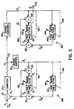
- the transmitter 10B differs from that in Figure 2 by the addition of a zero-based predictor 40 (having no feedback) which produces from the regenerated difference signal E j a partial predicted value X ⁇ jo .
- a second adder 42 sums the outputs X ⁇ jo , X ⁇ jp of the zero-based predictor 40 and the pole-based predictor 18 to produce the predicted value X j .
- the coefficients of predictor 40 adaptive as signified by arrow 44, are adaptive only in dependence upon difference signal ⁇ j as signified by broken line 46 and it has no feedback loop.
- a corresponding predictor 140 and adder 142 are provided in the receiver 12B.
- the zero-based predictor 40 might have six coefficients.
- the zero-based predictor coefficients may be derived in accordance with the teachings of U.S. Patent No. 4,317,208.
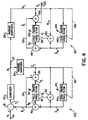
- the coefficients of the pole-based predictor 18 may be adapted in dependence upon the output of the additional predictor 40, as well as the difference signal ⁇ j .
- the receiver 12C has a corresponding third adder 150 connected to like manner.
Landscapes
- Engineering & Computer Science (AREA)
- Theoretical Computer Science (AREA)
- Compression, Expansion, Code Conversion, And Decoders (AREA)
Claims (26)
dadurch gekennzeichnet, daß das Prädiktormittel (18) ausgelegt ist zum Ableiten jedes Prädiktorkoeffizienten als einer nichtlinearen Funktion, abhängig von einer begrenzten Anzahl vergangener Werte des Differenzsignales oder des Residuals (Êj) und nicht direkt abhängig von dem rekonstruierten Signal X'j.


dadurch gekennzeichnet, daß


Priority Applications (1)
| Application Number | Priority Date | Filing Date | Title |
|---|---|---|---|
| AT84107530T ATE43762T1 (de) | 1983-07-18 | 1984-06-29 | Adaptives differentielles pcm-system mit durch residuum gesteuerter anpassung des rueckkopplungspraediktors. |
Applications Claiming Priority (4)
| Application Number | Priority Date | Filing Date | Title |
|---|---|---|---|
| CA000432615A CA1220867A (en) | 1983-07-18 | 1983-07-18 | Adaptive differential pcm system with residual-driven adaptation of feedback predictor |
| CA432615 | 1983-07-18 | ||
| US06/546,738 US4593398A (en) | 1983-07-18 | 1983-10-28 | Adaptive differential PCM system with residual-driven adaptation of feedback predictor |
| US546738 | 1983-10-28 |
Publications (3)
| Publication Number | Publication Date |
|---|---|
| EP0131817A2 EP0131817A2 (de) | 1985-01-23 |
| EP0131817A3 EP0131817A3 (en) | 1985-10-23 |
| EP0131817B1 true EP0131817B1 (de) | 1989-05-31 |
Family
ID=25670095
Family Applications (1)
| Application Number | Title | Priority Date | Filing Date |
|---|---|---|---|
| EP19840107530 Expired EP0131817B1 (de) | 1983-07-18 | 1984-06-29 | Adaptives differentielles PCM-System mit durch Residuum gesteuerter Anpassung des Rückkopplungsprädiktors |
Country Status (2)
| Country | Link |
|---|---|
| EP (1) | EP0131817B1 (de) |
| DE (1) | DE3478552D1 (de) |
Families Citing this family (1)
| Publication number | Priority date | Publication date | Assignee | Title |
|---|---|---|---|---|
| DE19829382C2 (de) * | 1998-07-01 | 2001-06-21 | Bundesrep Deutschland | Verfahren zur Rekonstruktion von optischen, mechanischen, elektrischen oder anderen Meßgrößen |
-
1984
- 1984-06-29 EP EP19840107530 patent/EP0131817B1/de not_active Expired
- 1984-06-29 DE DE8484107530T patent/DE3478552D1/de not_active Expired
Also Published As
| Publication number | Publication date |
|---|---|
| DE3478552D1 (en) | 1989-07-06 |
| EP0131817A2 (de) | 1985-01-23 |
| EP0131817A3 (en) | 1985-10-23 |
Similar Documents
| Publication | Publication Date | Title |
|---|---|---|
| US4317208A (en) | ADPCM System for speech or like signals | |
| US4064379A (en) | Logarithmic echo canceller | |
| US4912758A (en) | Full-duplex digital speakerphone | |
| EP0518383B1 (de) | Verfahren und Einrichtung zur Echokompensation in einem digitalen Fernmeldesystem | |
| JP2853455B2 (ja) | エコーキャンセラ | |
| US4751736A (en) | Variable bit rate speech codec with backward-type prediction and quantization | |
| US4998241A (en) | Echo canceller | |
| US4831636A (en) | Coding transmission equipment for carrying out coding with adaptive quantization | |
| US4679230A (en) | Echo canceller and center clipper control arrangement | |
| US6816592B1 (en) | Echo cancellation in digital data transmission system | |
| JP2794999B2 (ja) | エコーキャンセル方式 | |
| US5790632A (en) | Method and apparatus for echo canceling accounting for companding induced quantization error | |
| CN1269926A (zh) | 用于回波估算和抑制的方法和设备 | |
| US4411001A (en) | Differential pulse code modulation transmission system | |
| US4554670A (en) | System and method for ADPCM transmission of speech or like signals | |
| US4593398A (en) | Adaptive differential PCM system with residual-driven adaptation of feedback predictor | |
| Kanemasa et al. | An adaptive-step sign algorithm for fast convergence of a data echo canceller | |
| US5359656A (en) | Adaptive echo cancellation apparatus | |
| EP0131817A2 (de) | Adaptives differentielles PCM-System mit durch Residuum gesteuerter Anpassung des Rückkopplungsprädiktors | |
| US5953410A (en) | Method and arrangement for echo compensation | |
| US5621760A (en) | Speech coding transmission system and coder and decoder therefor | |
| US4481644A (en) | Differential pulse code modulation transmission system | |
| JPH0616580B2 (ja) | 双方向デイジタル伝送システム用エコ−・キヤンセラ | |
| US20010040927A1 (en) | Adaptive differential pulse code modulation system and method utilizing whitening filter for updating of predictor coefficients | |
| CA1156369A (en) | Adaptive differential pulse code modulation system for speech or like signals |
Legal Events
| Date | Code | Title | Description |
|---|---|---|---|
| PUAI | Public reference made under article 153(3) epc to a published international application that has entered the european phase |
Free format text: ORIGINAL CODE: 0009012 |
|
| AK | Designated contracting states |
Designated state(s): AT DE FR GB IT NL SE |
|
| PUAL | Search report despatched |
Free format text: ORIGINAL CODE: 0009013 |
|
| AK | Designated contracting states |
Designated state(s): AT DE FR GB IT NL SE |
|
| 17P | Request for examination filed |
Effective date: 19860115 |
|
| 17Q | First examination report despatched |
Effective date: 19871103 |
|
| GRAA | (expected) grant |
Free format text: ORIGINAL CODE: 0009210 |
|
| AK | Designated contracting states |
Kind code of ref document: B1 Designated state(s): AT DE FR GB IT NL SE |
|
| REF | Corresponds to: |
Ref document number: 43762 Country of ref document: AT Date of ref document: 19890615 Kind code of ref document: T |
|
| REF | Corresponds to: |
Ref document number: 3478552 Country of ref document: DE Date of ref document: 19890706 |
|
| ET | Fr: translation filed | ||
| ITF | It: translation for a ep patent filed | ||
| PLBE | No opposition filed within time limit |
Free format text: ORIGINAL CODE: 0009261 |
|
| STAA | Information on the status of an ep patent application or granted ep patent |
Free format text: STATUS: NO OPPOSITION FILED WITHIN TIME LIMIT |
|
| 26N | No opposition filed | ||
| PGFP | Annual fee paid to national office [announced via postgrant information from national office to epo] |
Ref country code: AT Payment date: 19900612 Year of fee payment: 7 |
|
| ITTA | It: last paid annual fee | ||
| PGFP | Annual fee paid to national office [announced via postgrant information from national office to epo] |
Ref country code: NL Payment date: 19900630 Year of fee payment: 7 |
|
| PG25 | Lapsed in a contracting state [announced via postgrant information from national office to epo] |
Ref country code: AT Effective date: 19910629 |
|
| PG25 | Lapsed in a contracting state [announced via postgrant information from national office to epo] |
Ref country code: NL Effective date: 19920101 |
|
| NLV4 | Nl: lapsed or anulled due to non-payment of the annual fee | ||
| EAL | Se: european patent in force in sweden |
Ref document number: 84107530.2 |
|
| REG | Reference to a national code |
Ref country code: GB Ref legal event code: IF02 |
|
| PGFP | Annual fee paid to national office [announced via postgrant information from national office to epo] |
Ref country code: FR Payment date: 20030523 Year of fee payment: 20 |
|
| PGFP | Annual fee paid to national office [announced via postgrant information from national office to epo] |
Ref country code: SE Payment date: 20030526 Year of fee payment: 20 |
|
| PGFP | Annual fee paid to national office [announced via postgrant information from national office to epo] |
Ref country code: GB Payment date: 20030529 Year of fee payment: 20 |
|
| PGFP | Annual fee paid to national office [announced via postgrant information from national office to epo] |
Ref country code: DE Payment date: 20030630 Year of fee payment: 20 |
|
| REG | Reference to a national code |
Ref country code: FR Ref legal event code: CD |
|
| PG25 | Lapsed in a contracting state [announced via postgrant information from national office to epo] |
Ref country code: GB Free format text: LAPSE BECAUSE OF EXPIRATION OF PROTECTION Effective date: 20040628 |
|
| REG | Reference to a national code |
Ref country code: GB Ref legal event code: PE20 |
|
| EUG | Se: european patent has lapsed |