EP0131157A2 - Rotary compressor - Google Patents
Rotary compressor Download PDFInfo
- Publication number
- EP0131157A2 EP0131157A2 EP84106434A EP84106434A EP0131157A2 EP 0131157 A2 EP0131157 A2 EP 0131157A2 EP 84106434 A EP84106434 A EP 84106434A EP 84106434 A EP84106434 A EP 84106434A EP 0131157 A2 EP0131157 A2 EP 0131157A2
- Authority
- EP
- European Patent Office
- Prior art keywords
- air
- rotary
- center housing
- accumulator
- sleeve
- Prior art date
- Legal status (The legal status is an assumption and is not a legal conclusion. Google has not performed a legal analysis and makes no representation as to the accuracy of the status listed.)
- Granted
Links
Images


Classifications
-
- F—MECHANICAL ENGINEERING; LIGHTING; HEATING; WEAPONS; BLASTING
- F04—POSITIVE - DISPLACEMENT MACHINES FOR LIQUIDS; PUMPS FOR LIQUIDS OR ELASTIC FLUIDS
- F04C—ROTARY-PISTON, OR OSCILLATING-PISTON, POSITIVE-DISPLACEMENT MACHINES FOR LIQUIDS; ROTARY-PISTON, OR OSCILLATING-PISTON, POSITIVE-DISPLACEMENT PUMPS
- F04C18/00—Rotary-piston pumps specially adapted for elastic fluids
- F04C18/30—Rotary-piston pumps specially adapted for elastic fluids having the characteristics covered by two or more of groups F04C18/02, F04C18/08, F04C18/22, F04C18/24, F04C18/48, or having the characteristics covered by one of these groups together with some other type of movement between co-operating members
- F04C18/34—Rotary-piston pumps specially adapted for elastic fluids having the characteristics covered by two or more of groups F04C18/02, F04C18/08, F04C18/22, F04C18/24, F04C18/48, or having the characteristics covered by one of these groups together with some other type of movement between co-operating members having the movement defined in group F04C18/08 or F04C18/22 and relative reciprocation between the co-operating members
- F04C18/344—Rotary-piston pumps specially adapted for elastic fluids having the characteristics covered by two or more of groups F04C18/02, F04C18/08, F04C18/22, F04C18/24, F04C18/48, or having the characteristics covered by one of these groups together with some other type of movement between co-operating members having the movement defined in group F04C18/08 or F04C18/22 and relative reciprocation between the co-operating members with vanes reciprocating with respect to the inner member
- F04C18/348—Rotary-piston pumps specially adapted for elastic fluids having the characteristics covered by two or more of groups F04C18/02, F04C18/08, F04C18/22, F04C18/24, F04C18/48, or having the characteristics covered by one of these groups together with some other type of movement between co-operating members having the movement defined in group F04C18/08 or F04C18/22 and relative reciprocation between the co-operating members with vanes reciprocating with respect to the inner member the vanes positively engaging, with circumferential play, an outer rotatable member
Definitions
- the present invention relates to improvements in rotary sleeve bearing apparatus for a rotary compressor which is utilizable as a supercharger for an internal combustion engine and provided with a rotary sleeve mounted in a center housing for rotation with a plurality of vanes movable in a rotor which is eccentrically disposed in the rotary sleeve.
- a movable vane compressor of the type having a rotary sleeve supported by compressible fluid such as air is utilizable as a supercharger for an automobile engine required to run over a wide speed range.
- the rotary sleeve rotates together with a plurality of vanes to prevent frictional heat and wear at the apex of each vane. And yet it has the possibility of scuffing and seizure troubles if air is highly compressed in the compression working space confined among the rotary sleeve, the rotor and the adjacent vanes to push the rotary sleeve from within to the inner periphery of the center housing.
- the supplied air has a pulsating pressure resulted from that a cyclical change of compression ratio in the compression working space causes pulsation of air both in the compression working space and in the discharge chamber internally connected thereto.
- the pulsation in the air supplied into the air-bearing room may vibrate the rotary sleeve.
- the pulsation causes not only the rotary sleeve to contact the inner periphery of the center housing but also the vane to vibrate against the inner periphery of the rotary sleeve with the result that there occurs scuffing between the rotary sleeve and the center housing and wearing between the rotary sleeve and the vanes.
- Another problem is that, as the temperature rises in the discharge chamber or compression working space, the air supplied to the air-bearing room is insufficient in density to increase the bearing performance of the air-bearing room.
- the invention consists in the apparatus for a rotary compressor provided with a rotary sleeve rotatably mounted in a center housing, a rotor disposed within the rotary sleeve, a plurality of vanes movably fitted in the rotor, and a discharge chamber, the apparatus comprising a thin air-bearing room defined between the center housing and the rotary sleeve, an inlet provided in the inner surface of the center housing on which the rotary sleeve would be pressed by compressed air, and an air-supply passage extending to said inlet from either or both of the discharge chamber and a compression working space under the maximum pressure, wherein the air-supply passage is provided with an accumulator.
- the accumulator is formed as a hollow portion in the center housing.
- a relatively large hollow in the wall of the center housing is used for absorbing pulsations in the air extracted from the discharge chamber or compression working space.
- a plurality of fine bores in the suction side wall serves to lower the temperature of the extracted air. Therefore, an accumulator is preferably shaped in the form of combination of at least a large hollow in the thickened wall of the center housing with a plurality of fine bores in the suction side wall.
- the rotary sleeve in the compressor is free from surging even if the high temperature and pulsating air is supplied to the air-bearing room for supporting the rotary sleeve, because the aupplied air has its pulsation and temperature reduced by the inventive accumulator before entering the air-bearing room.
- Another advantage is that the air-bearing room prevents the rotary sleeve from contacting the center housing by the help of air sufficient in pressure and desity even when the compressor runs at high speeds.
- the known apparatus without an accumulator supplies the hot pulsating air to the air-bearing room in which the pulsation causes the rotary sleeve to surge and scuff to the center housing or the poor density of hot air fails to increase the bearing capacity.
- the apparatus of the invention allows the compressor to require less torque over a full speed range than the conventional one.
- the rotary compressor has a rotor 10 fixed to a rotor shaft 12, the rotor is eccentrically disposed in a rotary sleeve 30 to ratate in the direction as indicated by an arrow.
- the rotor 10 has a plurality of vanes 16 radially movably fitted in the respective vane grooves 15.
- the vane 16 has its apex in contact with the inner periphery of the rotary sleeve 30.
- the rotary-sleeve 30 is floatingly supported in an air-bearing room 40 defined between the outer periphery of the rotary sleeve and the inner periphery of the center housing 22.
- the width of the air-bearing room 40 is exaggeratedly illustrated but really less than 0.1 mm.
- the compression working space 43 has its maximum pressure immediately before internally connected to the discharge chamber 41 through the discharge port 42.
- An extract port 44 is provided to extract the maximum pressure air from the compression working space and another extract port 46 is provided in the discharge chamber 41.
- An inlet 71 is provided at the starting point of an area to which the rotary sleeve 30 is pushed from within by compressed air in the compression working space 43 and connected to the extract port 44 with the intervention of an air-supply passage 45.
- the another extract port 46 is connected to the air-supply passage 45 by an auxiliary passage 47 in which a cheque valve 76 is mounted.
- the air-supply and auxiliary passages 45, 47 are formed in the center housing but illustrated by imaginal lines as were outside the housing for convenience.
- the compression-side thickened-wall of the center housing 22 is formed with a hollow portion used as an accumulator 60, which is interposed between the inlet 71 and the air-supply passage 45.
- rotor 10 is integrally shaped with a shaft 12 rotatably supported by bearings 18, 19 in the respective front and rear side housings 21, 23 and fixed at the front end thereof to a pulley 14 which is rotated by an engine.
- a gascket is interposed between the rear side housing 23 and the rear cover 24 in which the discharge chamber and the suction chamber 51 are provided.
- the air-suppy passage 45 is connected to the entrance of the accumulator 60 the exit of which opens to the air-bearing room 40 between the center housing 22 and the rotary sleeve 30 through the inlet 71.
- the increased air flowing on the area prevents a direct contact between the rotary sleeve 30 and the center housing 22 when the rotary sleeve 30 is pushed to the area by the high-pressure air in the compression working space 43.
- the air having a pressure higher than the discharge pressure is supplied to increase the bearing effect of the air-bearing room 40 with the result that the rotary sleeve 30 is prevented against direct contact with the center housing 22.
- the pressure in the air-supply passage 45 descends below the discharge pressure to open the cheque valve 76, thereby allowing the discharge chamber 41 to supply air to the air-bearing room 40.
- the discharge chamber 41 can supply a sufficient air, in volume and pressure, to the bearing room 40, though its pressure is lower than the maximum in the working space.
- the air-bearing room 40 is capable to prevent a direct contact between the rotary sleeve 30 and the center housing 22.
- Each rotatiion of the rotor causes a cyclic change of pressure in the compression working space, so that air pulsates in the space and the discharge chamber internally connected to the space.
- the pulsating air is extracted and introduced through the air-supply passage 45 to the accumulator 60, in which the air has its pulses absorbed. Thereafter, the air without pulses is supplied through the inlet 71 to the air-bearing room 40, thereby the rotary sleeve 30 being free from surging due to pulsating air.
- the accumulator 60 is composed of a relatively largge hollow portion 61 and a plurality of relatively fine bores 62 respectively formed in the suction-side wall of the center housing 22.
- the fine bores 62 in the center housing 22 are connected in the form of a S-shaped line by intermittent grooves 63 formed in the respective front and rear side housings 21, 23 as seen in FIG. 4.
- the pulsating high-temperature air from the discharge chamber 41 firstly enters the large hollow portion 61 in which the pulsation is eliminated from the air and then passes through the jzigzag way portion 62, 63 of the accumulator 60 in which the temperature is considerably reduced by heat exchange with the relatively low-temperature suction-side wall of the center housing 22 before the air enters the air-bearing room 40 through the inlet 71 as seen in FIG. 3. Therefore, even if the discharge air is high in temperature, the air-bearing room is supplied with the low-temperature, high-pressure air to increase the bearing effect.
- a straightener 65 is mounted in the accumulator 60 to prevent abrasive sands or the like from entering the air-bearing room 40 to wear the outer surface of the rotary sleeve 30 as well as the inner surface of the center housing 22.
- the accumulator 60 has two relatively large hollows, one formed in the compression side wall of the center housing and the other in the suction side wall.
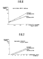
- FIGS. 6 and 7 show the results of a comparative test between the compressor with the inventive apparatus which is provided with an accumulator and that with the conventional without an accumulator.
- the graphs of FIGS. 6 and 7 show a relation between torque and discharge pressure when the compressor runs at a constant speed of 3000 rpm and that between torque and rotational speed when the compressor runs at a constant load, respectively. It is apparent from the graphs that the inventive apparatus allows the compressor to require less torque over a full speed range than the conventional and that the difference increases with discharge pressure.
Landscapes
- Engineering & Computer Science (AREA)
- Mechanical Engineering (AREA)
- General Engineering & Computer Science (AREA)
- Rotary Pumps (AREA)
- Applications Or Details Of Rotary Compressors (AREA)
Abstract
Description
- The present invention relates to improvements in rotary sleeve bearing apparatus for a rotary compressor which is utilizable as a supercharger for an internal combustion engine and provided with a rotary sleeve mounted in a center housing for rotation with a plurality of vanes movable in a rotor which is eccentrically disposed in the rotary sleeve.
- A movable vane compressor of the type having a rotary sleeve supported by compressible fluid such as air is utilizable as a supercharger for an automobile engine required to run over a wide speed range. The rotary sleeve rotates together with a plurality of vanes to prevent frictional heat and wear at the apex of each vane. And yet it has the possibility of scuffing and seizure troubles if air is highly compressed in the compression working space confined among the rotary sleeve, the rotor and the adjacent vanes to push the rotary sleeve from within to the inner periphery of the center housing. In Japanese Patent Application Serial Number Sho 58-28608, the inventors of this application have proposed to supply air to an air-bearing room between the inner periphery of the center housing and the outer periphery of the rotary sleeve through an inlet which is internally connected to one of the discharge chamber, the compression working space under the Maximum pressure, or the open air. The supplied air increases the flowing of air along an area of the compression side inner periphery of the center housing to protect scuffing between the rotary sleeve and the center housing. It is desirable for the air-bearing room to be supplied with the high-pressure air in the compression working space or discharge chamber. However, the supplied air has a pulsating pressure resulted from that a cyclical change of compression ratio in the compression working space causes pulsation of air both in the compression working space and in the discharge chamber internally connected thereto. The pulsation in the air supplied into the air-bearing room may vibrate the rotary sleeve. Especially, in high-speed and high-load operations, the pulsation causes not only the rotary sleeve to contact the inner periphery of the center housing but also the vane to vibrate against the inner periphery of the rotary sleeve with the result that there occurs scuffing between the rotary sleeve and the center housing and wearing between the rotary sleeve and the vanes. Another problem is that, as the temperature rises in the discharge chamber or compression working space, the air supplied to the air-bearing room is insufficient in density to increase the bearing performance of the air-bearing room.
- It is the primary object of the present invention to provide a rotary-sleeve bearing apparatus for a rotary compressor in which the air-bearing effect is less affected by the pulsation and temperature of the air which is extracted from the discharge chamber or compreesion working space and supplied to the air-bearing room.
- To attain the object as described above, the invention consists in the apparatus for a rotary compressor provided with a rotary sleeve rotatably mounted in a center housing, a rotor disposed within the rotary sleeve, a plurality of vanes movably fitted in the rotor, and a discharge chamber, the apparatus comprising a thin air-bearing room defined between the center housing and the rotary sleeve, an inlet provided in the inner surface of the center housing on which the rotary sleeve would be pressed by compressed air, and an air-supply passage extending to said inlet from either or both of the discharge chamber and a compression working space under the maximum pressure, wherein the air-supply passage is provided with an accumulator.
- The accumulator is formed as a hollow portion in the center housing. A relatively large hollow in the wall of the center housing is used for absorbing pulsations in the air extracted from the discharge chamber or compression working space. A plurality of fine bores in the suction side wall serves to lower the temperature of the extracted air. Therefore, an accumulator is preferably shaped in the form of combination of at least a large hollow in the thickened wall of the center housing with a plurality of fine bores in the suction side wall.
- One of the advantages offered by the present invention is that the rotary sleeve in the compressor is free from surging even if the high temperature and pulsating air is supplied to the air-bearing room for supporting the rotary sleeve, because the aupplied air has its pulsation and temperature reduced by the inventive accumulator before entering the air-bearing room. Another advantage is that the air-bearing room prevents the rotary sleeve from contacting the center housing by the help of air sufficient in pressure and desity even when the compressor runs at high speeds. In contrast, the known apparatus without an accumulator supplies the hot pulsating air to the air-bearing room in which the pulsation causes the rotary sleeve to surge and scuff to the center housing or the poor density of hot air fails to increase the bearing capacity. All in all, the apparatus of the invention allows the compressor to require less torque over a full speed range than the conventional one.
- One way of carrying out the invention is described in detail below with reference to drawings which illustrate preferred embodiments, in which:-
- FIG. 1 is a side elvation of the rotary compressor provided with the apparatus of the invention, the rear side housing of which is removed for convenience;
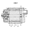
- FIG. 2 is a section taken along the line II-II of FIG. 1;
- FIG. 3 is a view of another embodiment, similar to FIG. 1;
- FIG. 4 is a section taken along the line IV-IV of FIG. 3;
- FIG. 5 is a view of a further embodiment, similar to FIG. 1; and
- FIGS. 6 and 7 are graphs showing the results of a comparative test between the inventive and kown apparatus.
- Referring initially to FIG. 1 in which the rotary compressor has a
rotor 10 fixed to arotor shaft 12, the rotor is eccentrically disposed in arotary sleeve 30 to ratate in the direction as indicated by an arrow. Therotor 10 has a plurality ofvanes 16 radially movably fitted in therespective vane grooves 15. Thevane 16 has its apex in contact with the inner periphery of therotary sleeve 30. The rotary-sleeve 30 is floatingly supported in an air-bearingroom 40 defined between the outer periphery of the rotary sleeve and the inner periphery of thecenter housing 22. The width of the air-bearingroom 40 is exaggeratedly illustrated but really less than 0.1 mm. - Two
adjacent vanes 16, while turning, forms acomprssion working space 43 in the suction side and a suction working space 53 in the suction side of the compressor, respectively. Thecompression working space 43 has its maximum pressure immediately before internally connected to thedischarge chamber 41 through thedischarge port 42. Anextract port 44 is provided to extract the maximum pressure air from the compression working space and anotherextract port 46 is provided in thedischarge chamber 41. Aninlet 71 is provided at the starting point of an area to which therotary sleeve 30 is pushed from within by compressed air in thecompression working space 43 and connected to theextract port 44 with the intervention of an air-supply passage 45. The anotherextract port 46 is connected to the air-supply passage 45 by anauxiliary passage 47 in which acheque valve 76 is mounted. The air-supply andauxiliary passages - The compression-side thickened-wall of the
center housing 22 is formed with a hollow portion used as anaccumulator 60, which is interposed between theinlet 71 and the air-supply passage 45. - As seen in FIG. 2,
rotor 10 is integrally shaped with ashaft 12 rotatably supported bybearings rear side housings pulley 14 which is rotated by an engine. A gascket is interposed between therear side housing 23 and therear cover 24 in which the discharge chamber and thesuction chamber 51 are provided. The air-suppy passage 45 is connected to the entrance of theaccumulator 60 the exit of which opens to the air-bearingroom 40 between thecenter housing 22 and therotary sleeve 30 through theinlet 71. - Upon rotation of the
rotor 10 of the compressor of FIGS. 1 and 2, air is gradually compressed in thecompression working space 43 defined between the twoadjacent vanes 16 and has its maximum prssure immediately before thecompression working space 43 is internally connected to thedischarge chamber 41. The maximum pressure air is extracted through theextract port 44 to the air-supply passage 45 and supplied to the air-bearingroom 40 from theinlet 71 at the starting point of the area to which therotary sleeve 30 is pushed from within by the compressed air in theworking space 43 so as to increase the bearing ability of the room. The increased air flowing on the area prevents a direct contact between therotary sleeve 30 and thecenter housing 22 when therotary sleeve 30 is pushed to the area by the high-pressure air in thecompression working space 43. In the initial, low and middle speed operations, the air having a pressure higher than the discharge pressure is supplied to increase the bearing effect of the air-bearingroom 40 with the result that therotary sleeve 30 is prevented against direct contact with thecenter housing 22. - When the rotor rotates at high speeds in which the air-bearing
room 40 needs air more than what can be extracted from the compression working space, the pressure in the air-supply passage 45 descends below the discharge pressure to open thecheque valve 76, thereby allowing thedischarge chamber 41 to supply air to the air-bearingroom 40. Thedischarge chamber 41 can supply a sufficient air, in volume and pressure, to thebearing room 40, though its pressure is lower than the maximum in the working space. Thus, the air-bearingroom 40 is capable to prevent a direct contact between therotary sleeve 30 and thecenter housing 22. - Each rotatiion of the rotor causes a cyclic change of pressure in the compression working space, so that air pulsates in the space and the discharge chamber internally connected to the space. The pulsating air is extracted and introduced through the air-
supply passage 45 to theaccumulator 60, in which the air has its pulses absorbed. Thereafter, the air without pulses is supplied through theinlet 71 to the air-bearingroom 40, thereby therotary sleeve 30 being free from surging due to pulsating air. The higher the running speed is, the larger the effect of the accumulator will be. Without the accumulator, the rotay sleeve would be influenced for bad by the pulsation in the air suppled to the air-bearing room, especialiy in high-speed runnings. - Referring to FIG. 3 in which is shown another embodiment, the
accumulator 60 is composed of a relatively larggehollow portion 61 and a plurality of relativelyfine bores 62 respectively formed in the suction-side wall of thecenter housing 22. Thefine bores 62 in thecenter housing 22 are connected in the form of a S-shaped line byintermittent grooves 63 formed in the respective front andrear side housings discharge chamber 41 firstly enters the largehollow portion 61 in which the pulsation is eliminated from the air and then passes through thejzigzag way portion accumulator 60 in which the temperature is considerably reduced by heat exchange with the relatively low-temperature suction-side wall of thecenter housing 22 before the air enters the air-bearingroom 40 through theinlet 71 as seen in FIG. 3. Therefore, even if the discharge air is high in temperature, the air-bearing room is supplied with the low-temperature, high-pressure air to increase the bearing effect. - As seen in FIG. 5 showing still another embodiment, a
straightener 65 is mounted in theaccumulator 60 to prevent abrasive sands or the like from entering the air-bearingroom 40 to wear the outer surface of therotary sleeve 30 as well as the inner surface of thecenter housing 22. Theaccumulator 60 has two relatively large hollows, one formed in the compression side wall of the center housing and the other in the suction side wall. - FIGS. 6 and 7 show the results of a comparative test between the compressor with the inventive apparatus which is provided with an accumulator and that with the conventional without an accumulator. The graphs of FIGS. 6 and 7 show a relation between torque and discharge pressure when the compressor runs at a constant speed of 3000 rpm and that between torque and rotational speed when the compressor runs at a constant load, respectively. It is apparent from the graphs that the inventive apparatus allows the compressor to require less torque over a full speed range than the conventional and that the difference increases with discharge pressure.
Claims (6)
Applications Claiming Priority (2)
| Application Number | Priority Date | Filing Date | Title |
|---|---|---|---|
| JP101714/83 | 1983-06-09 | ||
| JP58101714A JPS59229079A (en) | 1983-06-09 | 1983-06-09 | Fluid supporting device of rotary sleeve in rotary compressor |
Publications (3)
| Publication Number | Publication Date |
|---|---|
| EP0131157A2 true EP0131157A2 (en) | 1985-01-16 |
| EP0131157A3 EP0131157A3 (en) | 1985-05-02 |
| EP0131157B1 EP0131157B1 (en) | 1987-10-07 |
Family
ID=14307968
Family Applications (1)
| Application Number | Title | Priority Date | Filing Date |
|---|---|---|---|
| EP84106434A Expired EP0131157B1 (en) | 1983-06-09 | 1984-06-06 | Rotary compressor |
Country Status (6)
| Country | Link |
|---|---|
| US (1) | US4648818A (en) |
| EP (1) | EP0131157B1 (en) |
| JP (1) | JPS59229079A (en) |
| KR (1) | KR870001449B1 (en) |
| CA (1) | CA1237107A (en) |
| DE (2) | DE3466723D1 (en) |
Families Citing this family (4)
| Publication number | Priority date | Publication date | Assignee | Title |
|---|---|---|---|---|
| JPS61152986A (en) * | 1984-12-26 | 1986-07-11 | Mazda Motor Corp | Rotary compressor having rotary sleeve |
| JP5430393B2 (en) * | 2009-12-29 | 2014-02-26 | 株式会社ヴァレオジャパン | Vane type compressor |
| US9267504B2 (en) | 2010-08-30 | 2016-02-23 | Hicor Technologies, Inc. | Compressor with liquid injection cooling |
| US8794941B2 (en) | 2010-08-30 | 2014-08-05 | Oscomp Systems Inc. | Compressor with liquid injection cooling |
Citations (4)
| Publication number | Priority date | Publication date | Assignee | Title |
|---|---|---|---|---|
| AT48444B (en) * | 1910-04-07 | 1911-06-10 | Karl Wittig | Capsule plant. |
| AT73439B (en) * | 1910-04-07 | 1917-06-11 | Karl Wittig | Capsule plant. |
| DE1000559B (en) * | 1953-09-09 | 1957-01-10 | Ingbuero Dipl Ing Friedrich He | Multi-cell compressor with sickle-shaped work area |
| DE3237803A1 (en) * | 1981-10-13 | 1983-04-28 | Nippon Piston Ring Co., Ltd., Tokyo | ROTATIONAL COMPRESSOR |
Family Cites Families (3)
| Publication number | Priority date | Publication date | Assignee | Title |
|---|---|---|---|---|
| FR709820A (en) * | 1932-01-12 | 1931-08-13 | Method for preventing heating between friction surfaces | |
| US3834842A (en) * | 1971-12-06 | 1974-09-10 | Hydraulic Prod Inc | Hydraulic power translating device |
| JPS59213983A (en) * | 1983-05-20 | 1984-12-03 | Nippon Piston Ring Co Ltd | Device for fluidly supporting rotary sleeve in rotary compressor |
-
1983
- 1983-06-09 JP JP58101714A patent/JPS59229079A/en active Granted
-
1984
- 1984-06-06 EP EP84106434A patent/EP0131157B1/en not_active Expired
- 1984-06-06 DE DE8484106434T patent/DE3466723D1/en not_active Expired
- 1984-06-07 CA CA000456077A patent/CA1237107A/en not_active Expired
- 1984-06-07 DE DE19848417406U patent/DE8417406U1/en not_active Expired
- 1984-06-08 KR KR1019840003225A patent/KR870001449B1/en not_active IP Right Cessation
-
1985
- 1985-09-20 US US06/777,877 patent/US4648818A/en not_active Expired - Fee Related
Patent Citations (4)
| Publication number | Priority date | Publication date | Assignee | Title |
|---|---|---|---|---|
| AT48444B (en) * | 1910-04-07 | 1911-06-10 | Karl Wittig | Capsule plant. |
| AT73439B (en) * | 1910-04-07 | 1917-06-11 | Karl Wittig | Capsule plant. |
| DE1000559B (en) * | 1953-09-09 | 1957-01-10 | Ingbuero Dipl Ing Friedrich He | Multi-cell compressor with sickle-shaped work area |
| DE3237803A1 (en) * | 1981-10-13 | 1983-04-28 | Nippon Piston Ring Co., Ltd., Tokyo | ROTATIONAL COMPRESSOR |
Non-Patent Citations (1)
| Title |
|---|
| PNEUMATIC HANDBOOK, 5th edition, Trade and Technical Press Ltd., Morden, Surrey, England, pages 90 & 91 * |
Also Published As
| Publication number | Publication date |
|---|---|
| JPH036354B2 (en) | 1991-01-29 |
| US4648818A (en) | 1987-03-10 |
| EP0131157A3 (en) | 1985-05-02 |
| KR850000601A (en) | 1985-02-28 |
| DE8417406U1 (en) | 1984-10-18 |
| CA1237107A (en) | 1988-05-24 |
| KR870001449B1 (en) | 1987-08-06 |
| JPS59229079A (en) | 1984-12-22 |
| EP0131157B1 (en) | 1987-10-07 |
| DE3466723D1 (en) | 1987-11-12 |
Similar Documents
| Publication | Publication Date | Title |
|---|---|---|
| US4389171A (en) | Gas compressor of the scroll type having reduced starting torque | |
| JP2787145B2 (en) | Hermetic electric compressor | |
| US3558248A (en) | Screw type refrigerant compressor | |
| US4648819A (en) | Vane-type rotary compressor with rotary sleeve | |
| KR100322269B1 (en) | Oscillating Rotary Compressor | |
| US4594062A (en) | Vane type rotary compressor with rotary sleeve | |
| US4514157A (en) | Rotary vane compressor | |
| JP3361821B2 (en) | Fluid pump | |
| KR19980063888A (en) | Rotary compressor with discharge chamber pressure release groove | |
| US4564344A (en) | Rotary compressor having rotary sleeve for rotation with vanes | |
| EP0126478B1 (en) | Rotary sleeve bearing apparatus for rotary compressors | |
| EP0131157B1 (en) | Rotary compressor | |
| US4595347A (en) | Rotary compressor | |
| US4389170A (en) | Rotary vane pump with passage to the rotor and housing interface | |
| JP2583944B2 (en) | Compressor | |
| JP2603028Y2 (en) | Hermetic compressor and lubricating oil supply device | |
| US4657493A (en) | Rotary-sleeve supporting apparatus in rotary compressor | |
| US4595348A (en) | Apparatus for supporting rotary sleeve of rotary compressor by fluid | |
| JPH0312237B2 (en) | ||
| JPH0350313Y2 (en) | ||
| JPH0320556Y2 (en) | ||
| JPS63255588A (en) | Gas compressor | |
| JPS6345589Y2 (en) | ||
| JPH0235876B2 (en) | KAITENATSUSHUKUKI | |
| JPS59108890A (en) | Rotary compressor |
Legal Events
| Date | Code | Title | Description |
|---|---|---|---|
| PUAI | Public reference made under article 153(3) epc to a published international application that has entered the european phase |
Free format text: ORIGINAL CODE: 0009012 |
|
| AK | Designated contracting states |
Designated state(s): DE FR GB |
|
| PUAL | Search report despatched |
Free format text: ORIGINAL CODE: 0009013 |
|
| 17P | Request for examination filed |
Effective date: 19850102 |
|
| AK | Designated contracting states |
Designated state(s): DE FR GB |
|
| 17Q | First examination report despatched |
Effective date: 19860321 |
|
| GRAA | (expected) grant |
Free format text: ORIGINAL CODE: 0009210 |
|
| AK | Designated contracting states |
Kind code of ref document: B1 Designated state(s): DE FR GB |
|
| REF | Corresponds to: |
Ref document number: 3466723 Country of ref document: DE Date of ref document: 19871112 |
|
| ET | Fr: translation filed | ||
| PLBE | No opposition filed within time limit |
Free format text: ORIGINAL CODE: 0009261 |
|
| STAA | Information on the status of an ep patent application or granted ep patent |
Free format text: STATUS: NO OPPOSITION FILED WITHIN TIME LIMIT |
|
| 26N | No opposition filed | ||
| PGFP | Annual fee paid to national office [announced via postgrant information from national office to epo] |
Ref country code: DE Payment date: 19910729 Year of fee payment: 8 |
|
| PGFP | Annual fee paid to national office [announced via postgrant information from national office to epo] |
Ref country code: GB Payment date: 19920529 Year of fee payment: 9 |
|
| PGFP | Annual fee paid to national office [announced via postgrant information from national office to epo] |
Ref country code: FR Payment date: 19920616 Year of fee payment: 9 |
|
| PG25 | Lapsed in a contracting state [announced via postgrant information from national office to epo] |
Ref country code: DE Effective date: 19930302 |
|
| PG25 | Lapsed in a contracting state [announced via postgrant information from national office to epo] |
Ref country code: GB Effective date: 19930606 |
|
| GBPC | Gb: european patent ceased through non-payment of renewal fee |
Effective date: 19930606 |
|
| PG25 | Lapsed in a contracting state [announced via postgrant information from national office to epo] |
Ref country code: FR Effective date: 19940228 |
|
| REG | Reference to a national code |
Ref country code: FR Ref legal event code: ST |