EP0131102B1 - Regler veränderlicher Frequenz - Google Patents
Regler veränderlicher Frequenz Download PDFInfo
- Publication number
- EP0131102B1 EP0131102B1 EP84104944A EP84104944A EP0131102B1 EP 0131102 B1 EP0131102 B1 EP 0131102B1 EP 84104944 A EP84104944 A EP 84104944A EP 84104944 A EP84104944 A EP 84104944A EP 0131102 B1 EP0131102 B1 EP 0131102B1
- Authority
- EP
- European Patent Office
- Prior art keywords
- pulse
- counter
- carry signal
- limit
- coil
- Prior art date
- Legal status (The legal status is an assumption and is not a legal conclusion. Google has not performed a legal analysis and makes no representation as to the accuracy of the status listed.)
- Expired - Lifetime
Links
- 239000000463 material Substances 0.000 description 3
- 230000001960 triggered effect Effects 0.000 description 3
- 239000003990 capacitor Substances 0.000 description 1
- 238000010586 diagram Methods 0.000 description 1
- 230000001105 regulatory effect Effects 0.000 description 1
- 230000001360 synchronised effect Effects 0.000 description 1
Images
Classifications
-
- H—ELECTRICITY
- H02—GENERATION; CONVERSION OR DISTRIBUTION OF ELECTRIC POWER
- H02M—APPARATUS FOR CONVERSION BETWEEN AC AND AC, BETWEEN AC AND DC, OR BETWEEN DC AND DC, AND FOR USE WITH MAINS OR SIMILAR POWER SUPPLY SYSTEMS; CONVERSION OF DC OR AC INPUT POWER INTO SURGE OUTPUT POWER; CONTROL OR REGULATION THEREOF
- H02M5/00—Conversion of AC power input into AC power output, e.g. for change of voltage, for change of frequency, for change of number of phases
- H02M5/02—Conversion of AC power input into AC power output, e.g. for change of voltage, for change of frequency, for change of number of phases without intermediate conversion into DC
- H02M5/04—Conversion of AC power input into AC power output, e.g. for change of voltage, for change of frequency, for change of number of phases without intermediate conversion into DC by static converters
- H02M5/22—Conversion of AC power input into AC power output, e.g. for change of voltage, for change of frequency, for change of number of phases without intermediate conversion into DC by static converters using discharge tubes with control electrode or semiconductor devices with control electrode
- H02M5/25—Conversion of AC power input into AC power output, e.g. for change of voltage, for change of frequency, for change of number of phases without intermediate conversion into DC by static converters using discharge tubes with control electrode or semiconductor devices with control electrode using devices of a thyratron or thyristor type requiring extinguishing means
- H02M5/27—Conversion of AC power input into AC power output, e.g. for change of voltage, for change of frequency, for change of number of phases without intermediate conversion into DC by static converters using discharge tubes with control electrode or semiconductor devices with control electrode using devices of a thyratron or thyristor type requiring extinguishing means for conversion of frequency
-
- H—ELECTRICITY
- H02—GENERATION; CONVERSION OR DISTRIBUTION OF ELECTRIC POWER
- H02K—DYNAMO-ELECTRIC MACHINES
- H02K33/00—Motors with reciprocating, oscillating or vibrating magnet, armature or coil system
Definitions
- Certain types of vibratory material handling equipment such as parts feeders, for example, utilize an electromagnet as the exciting force.
- the coil of the electromagnet is energized only during a portion of the time.
- a lower frequency also reduces the stress on the mechanical system of the equipment and reduces the noise level resulting from its operation.
- a lower frequency also provides more efficient feeding of most materials. The optimum frequency will depend on a variety of factors, but one factor is the physical characteristics of the material being fed. In the past, a conventional type of variable frequency supply has required a large power supply or transistor bank.
- the present invention provides an electromagnetic feeder as specified in the appended claim 1 and which obviates the need for a large power supply or transistor bank and provides a plurality of discrete operating frequencies.
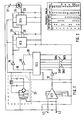
- L1 and L2 represent a conventional single phase, 60 hertz alternating current electrical power source with L2 being the ground.
- a zero crossing network IC1 which preferably is a CA-3059, is connected to L1 and L2 and provides a pulse centered at each zero crossing point of the A.C. line. Because the 60 Hz source crosses zero twice in each cycle, the output pulse frequency appearing on line 12 is 120 Hz.
- This output is fed to a synchronous, presettable 4 bit (divided by 16) counter IC2, which may be a 74161N, through a voltage divider network and an inverter gate 14.
- the inverter 14 is necessary if the 4 bit counter IC2 triggers on a positive going edge, as the 74161N does, because the zero crossing detector IC1 produces a positive edge just before the zero line is crossed. The inverter 14, therefore, causes the counter IC2 to be triggered at the proper time relative to the A.C. line.
- the output from the counter IC2 appears on line 16 and is fed to the input of a monostable multivibrator or one-shot timer IC3, which may be a 555 timer.
- An inverter 18 is also needed in the line 16 if the timer IC3 is triggered on a negative-going edge of the input pulse, as the 555 device is.
- the output pulse width of IC2 appears on line 20 and is varied by means of a phase control potentiometer 22.
- the negative edge of the positive square wave output by IC3 is used to trigger another one-shot timer IC4, which is preferably also a 555 timer.
- the timer IC4 has an associated resistance and capacitor recharged network selected to provide a fixed width output pulse on line 23 of short time duration, such as one milli-second, but of sufficient length to assure latching of the triac 24 during each conduction period.
- the triac 24 is triggered by the output, on line 23, of IC4 and is in series with the a coil 27 of the electromagnetic vibrator across the source L1 and L2. Thus, the coil 27 will be connected across the A.C. line whenever, and for as long as, the triac 24 is on.
- a conventional power supply 25 provides a regulated D.C. voltage to IC2, IC3 and IC4.
- the output of the counter IC2 is generated as a carry signal from the counter, which is capable of counting up in binary from 0 to 15 and is also presettable to a specific count.
- the carry signal appears as a high on line 16 and is inverted by inverter gate 26 so the load line 28 goes low.
- the counter is preset to a binary number determined by the condition of switches SW1, SW2, SW3 and SW4.
- the next pulse from detector IC1 causes the counter IC2 to count up from the preset number. Each successive pulse advances the counter until a carry signal is generated as the count or number goes to 15.
- the preset number is determined by which of the switches SW1, SW2, SW3 and SW4 are closed.
Landscapes
- Engineering & Computer Science (AREA)
- Power Engineering (AREA)
- Jigging Conveyors (AREA)
- Power Conversion In General (AREA)
- Control Of Ac Motors In General (AREA)
- Ac-Ac Conversion (AREA)
Claims (1)
- Elektromagnetische Zuführeinrichtung mit einer von einer Einphasen-Wechselstromquelle betätigbaren Spule und mit einer Steuereinrichtung zum Schaffen diskreter Erregerfrequenzen der Zuführeinrichtung, wobei die Steuereinrichtunga) einen als solchen bekannten Nulldurchgangdetektor, der einen ersten Impuls immer dann erzeugt, wenn die Stromquelle Null passiert, wobei ein Zähler den ersten Impuls empfängt und ein Trägersignal erzeugt,b) einen Binärzähler (IC2), welcher die ersten Impulse bis zu einer voreingestellten Grenze, welche einer diskreten Frequenz entspricht, binär zählt und bei Erreichen der Grenze ein Trägersignal erzeugt,c) eine Vielzahl von mit dem Binärzähler verbundenen Schaltern, um letzteren auf die Grenze voreinzustellen, um somit die diskreten Erregerfrequenzen bereitzustellen,d) eine Einrichtung, welche den Zähler auf die Grenze entsprechend der Lage der Schalter in Ansprechen auf das Trägersignal einstellt,e) eine als solche bekannte monostabile Multivibratoreinrichtung (IC3), welche angeschlossen ist, um das Trägersignal zu empfangen und zum Auslösen des Stromflusses durch die Spule einen zweiten Impuls zu erzeugen,f) einen Triac (24) umfaßt, der in Reihe mit der Spule (27) an der Wechselstromquelle angeschlossen und mit einem Zeitgeber (IC4) geschaltet ist und einen kurzen Ansteuerimpuls bereitstellt, um ein zweckmäßiges Ansteuern des Triac (24) zu gewährleisten, wobei der Zeitgeber (IC4) den zweiten Impuls empfängt.
Applications Claiming Priority (2)
| Application Number | Priority Date | Filing Date | Title |
|---|---|---|---|
| US491463 | 1983-05-04 | ||
| US06/491,463 US4811193A (en) | 1983-05-04 | 1983-05-04 | Variable frequency controller |
Publications (3)
| Publication Number | Publication Date |
|---|---|
| EP0131102A2 EP0131102A2 (de) | 1985-01-16 |
| EP0131102A3 EP0131102A3 (en) | 1985-05-22 |
| EP0131102B1 true EP0131102B1 (de) | 1990-02-07 |
Family
ID=23952336
Family Applications (1)
| Application Number | Title | Priority Date | Filing Date |
|---|---|---|---|
| EP84104944A Expired - Lifetime EP0131102B1 (de) | 1983-05-04 | 1984-05-03 | Regler veränderlicher Frequenz |
Country Status (9)
| Country | Link |
|---|---|
| US (1) | US4811193A (de) |
| EP (1) | EP0131102B1 (de) |
| JP (1) | JPS6026462A (de) |
| AU (1) | AU565189B2 (de) |
| BR (1) | BR8402098A (de) |
| CA (1) | CA1229656A (de) |
| DE (1) | DE3481349D1 (de) |
| ES (1) | ES8503164A1 (de) |
| ZA (1) | ZA843358B (de) |
Families Citing this family (5)
| Publication number | Priority date | Publication date | Assignee | Title |
|---|---|---|---|---|
| IE61980B1 (en) * | 1989-01-31 | 1994-12-14 | Tech Developments Limited | A timer unit |
| US5434457A (en) * | 1993-07-30 | 1995-07-18 | Josephs; Harold | Foot pedal safety switch and safety circuit |
| GB9402156D0 (en) * | 1994-02-04 | 1994-03-30 | Sgs Thomson Microelectronics | A multistandard ac/dc converter |
| US6116408A (en) * | 1998-07-30 | 2000-09-12 | Fmc Corporation | Apparatus and system for controlling the operating frequency of an electromagnetic vibratory feeder at a submultiple of the power line frequency |
| CN107543956B (zh) * | 2016-06-24 | 2021-07-27 | 东方电气集团东方电机有限公司 | 励磁系统同步信号调理电路及其实现方法 |
Family Cites Families (10)
| Publication number | Priority date | Publication date | Assignee | Title |
|---|---|---|---|---|
| AT245115B (de) * | 1964-08-11 | 1966-02-10 | Ife Ges Fuer Maschinen Und App | Schaltung zur Erzeugung von in der Phasenlage verschiebbaren Impulsen zur Stromsteuerung von Antriebsmagneten für Vibrationsgeräte |
| US3649893A (en) * | 1970-08-11 | 1972-03-14 | Allegheny Ludlum Ind Inc | Synchronized driver for electrical utilization devices |
| US3908158A (en) * | 1973-05-09 | 1975-09-23 | Borg Warner | Control system for adjusting a-c motor speed at line frequency or a subharmonic of the line frequency |
| JPS50103667A (de) * | 1974-01-22 | 1975-08-15 | ||
| US3950657A (en) * | 1974-10-21 | 1976-04-13 | Rca Corporation | Timer circuits |
| US4084155A (en) * | 1976-10-05 | 1978-04-11 | Fischer & Porter Co. | Two-wire transmitter with totalizing counter |
| US4231104A (en) * | 1978-04-26 | 1980-10-28 | Teradyne, Inc. | Generating timing signals |
| US4204141A (en) * | 1978-09-11 | 1980-05-20 | Esquire, Inc. | Adjustable DC pulse circuit for variation over a predetermined range using two timer networks |
| AU527427B2 (en) * | 1978-11-24 | 1983-03-03 | International Combustion Australia Ltd. | Means of energising vibrating feeders |
| US4337509A (en) * | 1980-07-22 | 1982-06-29 | Hitachi, Ltd. | Method and apparatus for controlling firing phases of thyristors |
-
1983
- 1983-05-04 US US06/491,463 patent/US4811193A/en not_active Expired - Fee Related
-
1984
- 1984-05-02 CA CA000453410A patent/CA1229656A/en not_active Expired
- 1984-05-03 EP EP84104944A patent/EP0131102B1/de not_active Expired - Lifetime
- 1984-05-03 DE DE8484104944T patent/DE3481349D1/de not_active Expired - Lifetime
- 1984-05-04 AU AU27701/84A patent/AU565189B2/en not_active Ceased
- 1984-05-04 JP JP59090071A patent/JPS6026462A/ja active Pending
- 1984-05-04 ES ES532210A patent/ES8503164A1/es not_active Expired
- 1984-05-04 ZA ZA843358A patent/ZA843358B/xx unknown
- 1984-05-04 BR BR8402098A patent/BR8402098A/pt not_active IP Right Cessation
Non-Patent Citations (2)
| Title |
|---|
| J. MARKUS: "Modern Electronic Circuits Reference Manuel", McGraw-Hill Book Co.,1980, page 369 * |
| Lexikon der Mikroelektronik, IWT Verlag, München, 1978, page 222 * |
Also Published As
| Publication number | Publication date |
|---|---|
| ZA843358B (en) | 1985-07-31 |
| BR8402098A (pt) | 1984-12-11 |
| DE3481349D1 (de) | 1990-03-15 |
| JPS6026462A (ja) | 1985-02-09 |
| EP0131102A2 (de) | 1985-01-16 |
| EP0131102A3 (en) | 1985-05-22 |
| CA1229656A (en) | 1987-11-24 |
| AU565189B2 (en) | 1987-09-10 |
| ES532210A0 (es) | 1985-02-01 |
| ES8503164A1 (es) | 1985-02-01 |
| AU2770184A (en) | 1984-11-08 |
| US4811193A (en) | 1989-03-07 |
Similar Documents
| Publication | Publication Date | Title |
|---|---|---|
| US3514682A (en) | Variable speed motor control arrangement | |
| US3418550A (en) | Brushless adjustable speed drive | |
| US3864618A (en) | Electro-mechanical vibratory drive control | |
| EP0083996A2 (de) | Elektronische Schaltvorrichtung mit Erregerwicklung | |
| US4811193A (en) | Variable frequency controller | |
| US3922589A (en) | Electrical control systems of electromagnetic vibrators | |
| US3304487A (en) | Regulated adjustable power supply having a primary current controlled by input and output voltages | |
| US3242410A (en) | Circuit for controlling energization of a direct current load | |
| US3336517A (en) | Speed regulating control system for universal motor | |
| EP0127775B1 (de) | Subharmonischer Regler für einen elektromagnetischen Erreger | |
| US4260947A (en) | Phase control circuit for regulating power | |
| US3436642A (en) | Polyphase to single phase static frequency multipliers with switching devices responsive to load conditions | |
| US4401925A (en) | Means of energizing vibrating feeders | |
| US3448361A (en) | Selective-frequency powerline load control | |
| US3411062A (en) | D. c. operated electronic governor for d.c. motor | |
| US4517500A (en) | Controller for electromagnetic exciter using power line subharmonic | |
| US3588656A (en) | Programmable electromechanical oscillator | |
| GB1099895A (en) | Improvements in or relating to dc-ac converters | |
| US3504250A (en) | Three phase electromechanical drive system | |
| US4414500A (en) | Variable motor speed control | |
| US4554490A (en) | Variable-frequency dual-motion feeder control using a single phase power source | |
| US2685056A (en) | Synchronizable vibrator-type inverter | |
| US3416055A (en) | Brushless electric motor circuitry | |
| GB1162989A (en) | Vibration Generator Controls | |
| GB1363036A (en) | Changing the frequency of a polyphase alternating current supply and apparatus therefor |
Legal Events
| Date | Code | Title | Description |
|---|---|---|---|
| PUAI | Public reference made under article 153(3) epc to a published international application that has entered the european phase |
Free format text: ORIGINAL CODE: 0009012 |
|
| AK | Designated contracting states |
Designated state(s): DE FR GB |
|
| PUAL | Search report despatched |
Free format text: ORIGINAL CODE: 0009013 |
|
| AK | Designated contracting states |
Designated state(s): DE FR GB |
|
| 17P | Request for examination filed |
Effective date: 19850416 |
|
| 17Q | First examination report despatched |
Effective date: 19870601 |
|
| GRAA | (expected) grant |
Free format text: ORIGINAL CODE: 0009210 |
|
| AK | Designated contracting states |
Kind code of ref document: B1 Designated state(s): DE FR GB |
|
| REF | Corresponds to: |
Ref document number: 3481349 Country of ref document: DE Date of ref document: 19900315 |
|
| ET | Fr: translation filed | ||
| PLBE | No opposition filed within time limit |
Free format text: ORIGINAL CODE: 0009261 |
|
| STAA | Information on the status of an ep patent application or granted ep patent |
Free format text: STATUS: NO OPPOSITION FILED WITHIN TIME LIMIT |
|
| 26N | No opposition filed | ||
| PGFP | Annual fee paid to national office [announced via postgrant information from national office to epo] |
Ref country code: DE Payment date: 19910411 Year of fee payment: 8 |
|
| PGFP | Annual fee paid to national office [announced via postgrant information from national office to epo] |
Ref country code: GB Payment date: 19910426 Year of fee payment: 8 |
|
| PGFP | Annual fee paid to national office [announced via postgrant information from national office to epo] |
Ref country code: FR Payment date: 19910430 Year of fee payment: 8 |
|
| PG25 | Lapsed in a contracting state [announced via postgrant information from national office to epo] |
Ref country code: GB Effective date: 19920503 |
|
| GBPC | Gb: european patent ceased through non-payment of renewal fee |
Effective date: 19920503 |
|
| PG25 | Lapsed in a contracting state [announced via postgrant information from national office to epo] |
Ref country code: FR Effective date: 19930129 |
|
| PG25 | Lapsed in a contracting state [announced via postgrant information from national office to epo] |
Ref country code: DE Effective date: 19930202 |
|
| REG | Reference to a national code |
Ref country code: FR Ref legal event code: ST |