EP0131077A1 - A device for attachment to drawtwister machines to produce multifilament yarns with S or Z twist effect - Google Patents
A device for attachment to drawtwister machines to produce multifilament yarns with S or Z twist effect Download PDFInfo
- Publication number
- EP0131077A1 EP0131077A1 EP83308027A EP83308027A EP0131077A1 EP 0131077 A1 EP0131077 A1 EP 0131077A1 EP 83308027 A EP83308027 A EP 83308027A EP 83308027 A EP83308027 A EP 83308027A EP 0131077 A1 EP0131077 A1 EP 0131077A1
- Authority
- EP
- European Patent Office
- Prior art keywords
- roll
- yarn
- drawtwister
- twisting
- shaft
- Prior art date
- Legal status (The legal status is an assumption and is not a legal conclusion. Google has not performed a legal analysis and makes no representation as to the accuracy of the status listed.)
- Granted
Links
- 230000000694 effects Effects 0.000 title description 3
- 229920002994 synthetic fiber Polymers 0.000 claims 2
- 239000004758 synthetic textile Substances 0.000 claims 2
- 238000004519 manufacturing process Methods 0.000 abstract description 13
- 238000010438 heat treatment Methods 0.000 abstract description 7
- 239000004753 textile Substances 0.000 abstract description 3
- 238000000034 method Methods 0.000 description 4
- 238000005265 energy consumption Methods 0.000 description 2
- 239000004744 fabric Substances 0.000 description 2
- 229910000792 Monel Inorganic materials 0.000 description 1
- CRQQGFGUEAVUIL-UHFFFAOYSA-N chlorothalonil Chemical compound ClC1=C(Cl)C(C#N)=C(Cl)C(C#N)=C1Cl CRQQGFGUEAVUIL-UHFFFAOYSA-N 0.000 description 1
- 230000005611 electricity Effects 0.000 description 1
- 238000005516 engineering process Methods 0.000 description 1
- 239000012467 final product Substances 0.000 description 1
- 238000011065 in-situ storage Methods 0.000 description 1
- 238000009434 installation Methods 0.000 description 1
- 238000012423 maintenance Methods 0.000 description 1
- 239000000463 material Substances 0.000 description 1
- 230000004048 modification Effects 0.000 description 1
- 238000012986 modification Methods 0.000 description 1
- 239000000047 product Substances 0.000 description 1
- 229910001220 stainless steel Inorganic materials 0.000 description 1
- 239000010935 stainless steel Substances 0.000 description 1
- 230000001131 transforming effect Effects 0.000 description 1
Images


Classifications
-
- D—TEXTILES; PAPER
- D02—YARNS; MECHANICAL FINISHING OF YARNS OR ROPES; WARPING OR BEAMING
- D02G—CRIMPING OR CURLING FIBRES, FILAMENTS, THREADS, OR YARNS; YARNS OR THREADS
- D02G1/00—Producing crimped or curled fibres, filaments, yarns, or threads, giving them latent characteristics
- D02G1/02—Producing crimped or curled fibres, filaments, yarns, or threads, giving them latent characteristics by twisting, fixing the twist and backtwisting, i.e. by imparting false twist
- D02G1/04—Devices for imparting false twist
- D02G1/08—Rollers or other friction causing elements
Abstract
Description
- The present invention relates to the manufacture of textile multifilament yarns and, in particular, to a device for twisting multifilament yarns in conventional drawtwister machines.
- Conventionally, textile yarns employed, for instance, in the manufacture of panty-hose and stockings for women are subjected to a twisting process in order to provide said yarns elasticity and fluffiness ("torque") in the yarns, giving the resulting fabric a great transparency, elasticity and softness. The process of false twisting or texturization, with 5 or Z twists, is carried out in special machines which produce the desired twist by means of magnetic spindles or friction discs.
- The machines equipped with magnetic spindles work at speeds ranging from 800,000 to 1,000,000 rpm. in order to produce multifilament yarns of approximately 1,000 - 5,000 twists per meter. Given:

- It is inferred that the productivity of conventional texturirg machines does not exceed 300 - 500 meters of yarn minute in each spindle.
- Convtional texturizing machines are mechanically sophisticated exhibiling a high technology; therefore, their amual cost is very high. Furthermore, due to their complexity, maintenance and service are very expensive requiring a high cost final product.
- Attempts to manufacture twisted yarns using drawtwister machines have failed and, in general, this idea has been abandoned by the experts in this art.
- Only one attempt of using drawtwister machines equipped with an additional and special device is known. It has been tried to twist monofilament yarns with these machines, making the yarn to run through two cylinder rolls arranged perpendicularly with their shafts in two parallel planes.
- Such a device does not allow the twisting of multifilament yarns.
- The object of the present invention is to provide a simple and low cost device, which can be attached to drawtwister machines to manufacture twisted multifilament yarns with either 5 or Z twist.
- The present invention permits a high productivity to be achieved in machines equipped with the twisting device in comparison with the productivity obtained with conventional machines.
- The productivity obtained reaches approximately 600 - 900 meters of yarn/minute in each device, in comparison with the 300/500 m/minute obtained in the conventional machines equipped with magnetic spindles. - The device of the present invention enables to obtain a low unit-cost of production in comparison with those obtained with conventional machines.
- The multflament varm twisted with the device of the present invention is of high quality, with a great number of twists per meter, and of good elasticity (in the range of 5 - 25%). making it possible to obtain fabrics for panty-hoses, stockings and the like of great transparency and smoothness. Conventional drawtwister machines equipped with the twisting device of the present invention operate with a low energy consumption in comparison with the high energy consumption of the conventional texturizing machines.
- The device of the present invention is very simple, small and of low cost.
- The present invertion enables, in situ, a modification of existing drawtwister machines, transforming them into machines that at a very low cost and without delay of time caused by stopping the manufacturing procedure, provide a special type of yarn highly suitable for manufacturing panty-hose or stockings and the like.
- The operating process in the modificated drawtwister machines according to the present invention is very simple in comparison with the process employed for instance, in magnetic spindles machines ("texturizers").
- The device of the present invention includes a pair of twisting rollers mounted to rotate freely in shafts, the axis of which are arranged at a substantial angle between them. the shafts being in spaced apart and parallel planes, one of the twisting rolls is a straight cylinder mounted on a fixed shaft whose- axis is perpendicular to a supporting plate and the other a frustrum with concave walls and with a determined radius of curvature mounted on a shaft whose axis is parallel to the surface of the supporting plate.
- The supporting plate of the twisting device is installed on a surface of the drawtwtster machine so that the shaft of the concave roll forms an angle of about 40°- 50° relative to an imaginary line connecting the yarn fastening roller and the surface of the godet .
- The twist of the yarn is set by heating the filament by a suitable heating element which heats the yarn before it passes around the twisting rollers.
- The present invention will be described with reference to the attached drawings, in which:
- Figure 1 is a view from above, showing schematically the twisting device according to the invention. for the manufacture of yarns with "5" twist.
- Figure 2, similar to Figure 1, shows the twisting device for the manufacturing of yarn with "Z" twist.
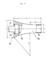
- Figure 3 is a plan view, partially in section, illustrating the shape and general dimensions of the concave fustrum twisting roll employed in the device of the invention.
- Figure 4 is a partial perspective and schematic view of a portion of a conventional drawtwister machine where a twistirg device is installed for the manufacturing of yarns with "S" twist and
- Figure 5 is a perspective view similar to Figure 4 illustrating a twisting device for the manufacturing of yarns with "Z" twist.
- As shown in Figure 1, the twistine device 1, according to the invention. comprises a
base plate 11 having a substantal- ly square shape where acylindrical roll 12 is mounted to rotate freely around ashaft 13 which extends along the Y-Y axis of thecylindrical roll 12. Preferably, but not necessarily,cylindrical roll 12 can be hollow and furnished with aflange 14 on the endadjacent plate 11 which projects radially outwardly from the surface of the lateral walls of the cylindrical roller. - A
twisting roll 15 is located laterally spaced from thecylindrical roll 12 and has substantially the shape of a frustrum having slightly concave lateral walls.Twisting roll 15 is shown in Figure 3 in greater detail. - The
shaft 16 oftwisting roll 15 which extends along the X-X axis forms a substantially right angle relative the shaft 13 (axis Y-Y of cylindrical roll 12) and consequently lies substantially parallel to the upper face ofbase plate 11. The conical-concave roll 15 is mounted to rotate freely aroundshaft 16 which is fixed to aconsole 17 located at a substantially right angle relative to the upper face ofbase plate 11. - In order to simplify the installation of the twisting rolls in a surface of a drawtwister machine, the
base plate 11 can be furnished withholes 18, through which bolts (not shown) can be screwed into the drawtwister machine. - The position of the
rolls concave roll 15 is installed with its axial shaft X-X located in a totally opposed position with respect to the pesition shown in Figure 1. This Figure 2 location forrolls - In Figure 3, the
twisting roll 15 is shown schematacally and partially, in a section view. The body of the roll has a substantially truncated shape, being preferentially hollow and with lateral walls defined by aconcave zone 20, with a radius of curvature R and acylindrical zone 21 of length A and diameter d; the base 22 of thetwisting roll 15. of diameter D, is provided with abearing 23, for instance, of the needle type or similar, which enables thetwisting roll 15 to rotate freely aroundshaft 16. - It has been discovered that, advantageously, the dimensions which define the geometry of the
twisting roll 15. have the following relations between them, as illustrated in Figure 3: -


- Preferentially, the length L of the conical-
concave twisting roll 15 is between 20 and 90 mm. -
Twisting rolls - It has also been discovered that a better twist effect on the yarn is obtained if the surface finish of the cylinder walls is of the non-brilliant type ("dull") with a very slight rugosity or wrinkled surface.
- In Figure 4, a twisting device as in Figure 1 is shown which has been placed on the vertical surface V of a drawiwister machine.
- A continous texile yarn of
syntheric faber 31, fed from a creel (not shown) is wound around afastening roll 32, which is fractionally driven by theimpeller shaft 33 which rotates at a predetermined angular speed. Theyarn 31, after making contact with oneyarn guide 34, is wound (one or more time) around aheating element 35. Theheating element 35, operated by electricity or by other suitable means, can rotate, if desired, freely around its axle due to the frictional drive ofyarn 31, as will be later explained. - The
yarn 31, after being heated when running over theheater 35, is caused to pass around the conical-concave twisting roll 15, around thecylindrical roll 12, again around thetwisting roll 15 and finally is wound four or five times around the drivengodet 36 which rotates at an angular speed between 1,1 and 5 times greater than the angular speed of theimpeller shaft 33. - The greater angular speed of the
godet 36 relative toimpeller shaft 33 causesyarn 31 to be drawn in a conventional way already known in the art. - The friction resulting from the drive of yarn3l around the
heater 35 causes the heating reel to rotate freely. Theyarn 31 is heated up to the proper temperature to set up the twist on theyarn 31 which will be produced by means of the conical-concave twisting roll 15 and thecylindrical roll 12; the rollers rotating freely under the action of the frictional drive produced by theyarn 31. - The drive of the yarn at high linear speed on the conical-
concave twisting roll 15 causes the yarn to slide up and down on theconcave surface 20 of theroll 15, thus producing an 5 twist effect on theyarn 31 which twist is due to the temperature provided byheater 35. - The
yarn 31, already twisted, is transferred from thegodet 36 to a cops or winder cylinder (not shown) and later is knit by circular machines to manufacture panty-hose stockings and other products. - Figure 5 illustrates the position of the device la of Figure 2, in which Z twist is obtained on the
yarn 31 in the same way that device 1 (shown in Figure 4), produces S twist. Thus, the device 1 is located to one side, or to the other side of the yarn path from thefastening roller 32 to thegodet 36, depending upon whether S or Z twisting is required. - It will be noted that the device is mounted via its supporting
plate 11 on the support surface V of the drawtwister machine in such a way that theshaft 16 of theconcave roll 15 forms an angle of about 400 - 60° relative to an imaginary line connecting thefastening roller 32 and the surface of thegodet 36 i.e. relative to the yarn as it is driven from thefastening roller 32 by thegodet 36. Also, theshaft 13 of theroll 12 extends transversely of the yarn.
Claims (6)

Priority Applications (1)
| Application Number | Priority Date | Filing Date | Title |
|---|---|---|---|
| AT83308027T ATE31089T1 (en) | 1983-07-07 | 1983-12-29 | ADDITIONAL DEVICE FOR DRAFT TWISTING MACHINES FOR MANUFACTURING MULTIFILAMENT YARN WITH S OR Z TWIST EFFECT. |
Applications Claiming Priority (2)
| Application Number | Priority Date | Filing Date | Title |
|---|---|---|---|
| US06/511,703 US4562694A (en) | 1983-07-07 | 1983-07-07 | Device for attachment to drawtwister machines to produce multifilament yarns with S or Z twist effect |
| US511703 | 1983-07-07 |
Publications (2)
| Publication Number | Publication Date |
|---|---|
| EP0131077A1 true EP0131077A1 (en) | 1985-01-16 |
| EP0131077B1 EP0131077B1 (en) | 1987-11-25 |
Family
ID=24036076
Family Applications (1)
| Application Number | Title | Priority Date | Filing Date |
|---|---|---|---|
| EP83308027A Expired EP0131077B1 (en) | 1983-07-07 | 1983-12-29 | A device for attachment to drawtwister machines to produce multifilament yarns with s or z twist effect |
Country Status (6)
| Country | Link |
|---|---|
| US (1) | US4562694A (en) |
| EP (1) | EP0131077B1 (en) |
| AR (1) | AR231313A1 (en) |
| AT (1) | ATE31089T1 (en) |
| DE (1) | DE3374699D1 (en) |
| MX (1) | MX158044A (en) |
Families Citing this family (2)
| Publication number | Priority date | Publication date | Assignee | Title |
|---|---|---|---|---|
| DE3519102A1 (en) * | 1985-05-28 | 1986-12-04 | Fritz 7347 Bad Überkingen Stahlecker | FRICTION ROLLER FOR A DE-FRICTION SPINNING DEVICE |
| DE3735942A1 (en) * | 1987-10-23 | 1989-05-03 | Barmag Barmer Maschf | FALSE SPIRIT ROLL |
Citations (4)
| Publication number | Priority date | Publication date | Assignee | Title |
|---|---|---|---|---|
| US3327461A (en) * | 1965-06-17 | 1967-06-27 | Turbo Machine Co | Apparatus and method for producing false twist in yarn |
| US3559391A (en) * | 1968-06-28 | 1971-02-02 | American Enka Corp | Production of torque yarn |
| GB1280470A (en) * | 1968-10-31 | 1972-07-05 | Scragg & Sons | False twisting apparatus |
| DE2460031A1 (en) * | 1973-12-31 | 1975-07-10 | Rudolf Gehring | Thermoplastic yarn false twisting process - uses a conical rotary false twister with constant path of yarn travel |
Family Cites Families (8)
| Publication number | Priority date | Publication date | Assignee | Title |
|---|---|---|---|---|
| US28117A (en) * | 1860-05-01 | Smut-machine | ||
| FR1194016A (en) * | 1957-05-08 | 1959-11-06 | ||
| NL253655A (en) * | 1959-07-15 | |||
| CH397493A (en) * | 1963-01-05 | 1965-08-15 | Rieter Ag Maschf | Device for monitoring the thread run on draw twisting machines and the like |
| BE754695A (en) * | 1969-10-27 | 1971-01-18 | Glanzstoff Ag | DEVICE FOR GIVING A FALSE TORSION TO MONOFILAMENTS OR ENDLESS THREADS |
| US3735575A (en) * | 1970-12-23 | 1973-05-29 | S Hattori | Spinning apparatus for continuous operation |
| US3782090A (en) * | 1971-12-08 | 1974-01-01 | Chadbourn Inc | Method and apparatus for producing textured yarn |
| US3816989A (en) * | 1973-08-08 | 1974-06-18 | Akzona Inc | Yarn driven friction falsetwister |
-
1983
- 1983-07-07 US US06/511,703 patent/US4562694A/en not_active Expired - Fee Related
- 1983-10-06 AR AR294466A patent/AR231313A1/en active
- 1983-10-13 MX MX199103A patent/MX158044A/en unknown
- 1983-12-29 DE DE8383308027T patent/DE3374699D1/en not_active Expired
- 1983-12-29 EP EP83308027A patent/EP0131077B1/en not_active Expired
- 1983-12-29 AT AT83308027T patent/ATE31089T1/en active
Patent Citations (4)
| Publication number | Priority date | Publication date | Assignee | Title |
|---|---|---|---|---|
| US3327461A (en) * | 1965-06-17 | 1967-06-27 | Turbo Machine Co | Apparatus and method for producing false twist in yarn |
| US3559391A (en) * | 1968-06-28 | 1971-02-02 | American Enka Corp | Production of torque yarn |
| GB1280470A (en) * | 1968-10-31 | 1972-07-05 | Scragg & Sons | False twisting apparatus |
| DE2460031A1 (en) * | 1973-12-31 | 1975-07-10 | Rudolf Gehring | Thermoplastic yarn false twisting process - uses a conical rotary false twister with constant path of yarn travel |
Also Published As
| Publication number | Publication date |
|---|---|
| MX158044A (en) | 1988-12-29 |
| AR231313A1 (en) | 1984-10-31 |
| ATE31089T1 (en) | 1987-12-15 |
| DE3374699D1 (en) | 1988-01-07 |
| US4562694A (en) | 1986-01-07 |
| EP0131077B1 (en) | 1987-11-25 |
Similar Documents
| Publication | Publication Date | Title |
|---|---|---|
| US4351146A (en) | Process and device for producing a yarn having alternate twists of opposite directions | |
| US4130983A (en) | Yarn spinning apparatus and process | |
| US3564677A (en) | Method and apparatus of treating material to change its configuration | |
| US2914810A (en) | Crimping of textile fibres | |
| US4302925A (en) | Multi-component spun yarn and method and apparatus for manufacturing same | |
| WO1997032064A1 (en) | Reducing end breaks in the spinning or twisting of yarn | |
| US4676062A (en) | Method and device for the formation of spinning fibers | |
| US4736578A (en) | Method for forming a slub yarn | |
| US4027467A (en) | Uniroll false twist device and method | |
| US2999351A (en) | Bulky yarn | |
| US3527043A (en) | Means and process for producing a false twist by friction | |
| US2979882A (en) | Method and apparatus for stretching and twisting continuous filament yarn | |
| US2983026A (en) | Method for producing crimped fiber | |
| US4302926A (en) | Multi-component yarn and method of apparatus for its manufacture | |
| US3805344A (en) | Variable feed means for jet texturing apparatus | |
| US3645080A (en) | Apparatus and method for manufacturing a fluffy yarn | |
| US3855772A (en) | Method of and apparatus for producing yarn | |
| GB2045288A (en) | Process for producing a combination yarn | |
| EP0131077B1 (en) | A device for attachment to drawtwister machines to produce multifilament yarns with s or z twist effect | |
| JPH07103499B2 (en) | False twisting device | |
| US3330104A (en) | False twist spindle with auxiliary reverse-twist element | |
| US4112667A (en) | Apparatus and process suitable for twist-drawing a yarn | |
| JPS5916004B2 (en) | spinning equipment | |
| CN219430211U (en) | System for producing yarn | |
| US4573312A (en) | Friction spinning apparatus |
Legal Events
| Date | Code | Title | Description |
|---|---|---|---|
| PUAI | Public reference made under article 153(3) epc to a published international application that has entered the european phase |
Free format text: ORIGINAL CODE: 0009012 |
|
| AK | Designated contracting states |
Designated state(s): AT BE CH DE FR GB IT LI LU NL SE |
|
| 17P | Request for examination filed |
Effective date: 19850703 |
|
| 17Q | First examination report despatched |
Effective date: 19860606 |
|
| GRAA | (expected) grant |
Free format text: ORIGINAL CODE: 0009210 |
|
| ITF | It: translation for a ep patent filed |
Owner name: SOCIETA' ITALIANA BREVETTI S.P.A. |
|
| AK | Designated contracting states |
Kind code of ref document: B1 Designated state(s): AT BE CH DE FR GB IT LI LU NL SE |
|
| REF | Corresponds to: |
Ref document number: 31089 Country of ref document: AT Date of ref document: 19871215 Kind code of ref document: T |
|
| PG25 | Lapsed in a contracting state [announced via postgrant information from national office to epo] |
Ref country code: LU Free format text: LAPSE BECAUSE OF NON-PAYMENT OF DUE FEES Effective date: 19871231 |
|
| REF | Corresponds to: |
Ref document number: 3374699 Country of ref document: DE Date of ref document: 19880107 |
|
| ET | Fr: translation filed | ||
| PLBE | No opposition filed within time limit |
Free format text: ORIGINAL CODE: 0009261 |
|
| STAA | Information on the status of an ep patent application or granted ep patent |
Free format text: STATUS: NO OPPOSITION FILED WITHIN TIME LIMIT |
|
| 26N | No opposition filed | ||
| PGFP | Annual fee paid to national office [announced via postgrant information from national office to epo] |
Ref country code: GB Payment date: 19901207 Year of fee payment: 8 |
|
| PGFP | Annual fee paid to national office [announced via postgrant information from national office to epo] |
Ref country code: SE Payment date: 19901219 Year of fee payment: 8 Ref country code: LU Payment date: 19901219 Year of fee payment: 8 |
|
| PGFP | Annual fee paid to national office [announced via postgrant information from national office to epo] |
Ref country code: CH Payment date: 19901224 Year of fee payment: 8 |
|
| PGFP | Annual fee paid to national office [announced via postgrant information from national office to epo] |
Ref country code: AT Payment date: 19901227 Year of fee payment: 8 |
|
| PGFP | Annual fee paid to national office [announced via postgrant information from national office to epo] |
Ref country code: NL Payment date: 19901231 Year of fee payment: 8 |
|
| PGFP | Annual fee paid to national office [announced via postgrant information from national office to epo] |
Ref country code: BE Payment date: 19910114 Year of fee payment: 8 |
|
| PGFP | Annual fee paid to national office [announced via postgrant information from national office to epo] |
Ref country code: DE Payment date: 19910115 Year of fee payment: 8 |
|
| PGFP | Annual fee paid to national office [announced via postgrant information from national office to epo] |
Ref country code: FR Payment date: 19910124 Year of fee payment: 8 |
|
| EPTA | Lu: last paid annual fee | ||
| PG25 | Lapsed in a contracting state [announced via postgrant information from national office to epo] |
Ref country code: GB Effective date: 19911229 Ref country code: AT Effective date: 19911229 |
|
| PG25 | Lapsed in a contracting state [announced via postgrant information from national office to epo] |
Ref country code: SE Effective date: 19911230 |
|
| ITTA | It: last paid annual fee | ||
| PG25 | Lapsed in a contracting state [announced via postgrant information from national office to epo] |
Ref country code: LI Effective date: 19911231 Ref country code: CH Effective date: 19911231 Ref country code: BE Effective date: 19911231 |
|
| BERE | Be: lapsed |
Owner name: SUMAR CESAR Effective date: 19911231 |
|
| PG25 | Lapsed in a contracting state [announced via postgrant information from national office to epo] |
Ref country code: NL Effective date: 19920701 |
|
| NLV4 | Nl: lapsed or anulled due to non-payment of the annual fee | ||
| GBPC | Gb: european patent ceased through non-payment of renewal fee | ||
| PG25 | Lapsed in a contracting state [announced via postgrant information from national office to epo] |
Ref country code: FR Effective date: 19920831 |
|
| REG | Reference to a national code |
Ref country code: CH Ref legal event code: PL |
|
| PG25 | Lapsed in a contracting state [announced via postgrant information from national office to epo] |
Ref country code: DE Effective date: 19920901 |
|
| REG | Reference to a national code |
Ref country code: FR Ref legal event code: ST |
|
| EUG | Se: european patent has lapsed |
Ref document number: 83308027.8 Effective date: 19920704 |