EP0130983B1 - Variable-camber airfoil - Google Patents
Variable-camber airfoil Download PDFInfo
- Publication number
- EP0130983B1 EP0130983B1 EP83901268A EP83901268A EP0130983B1 EP 0130983 B1 EP0130983 B1 EP 0130983B1 EP 83901268 A EP83901268 A EP 83901268A EP 83901268 A EP83901268 A EP 83901268A EP 0130983 B1 EP0130983 B1 EP 0130983B1
- Authority
- EP
- European Patent Office
- Prior art keywords
- panel
- link
- camber
- airfoil
- nose structure
- Prior art date
- Legal status (The legal status is an assumption and is not a legal conclusion. Google has not performed a legal analysis and makes no representation as to the accuracy of the status listed.)
- Expired
Links
Images


Classifications
-
- B—PERFORMING OPERATIONS; TRANSPORTING
- B64—AIRCRAFT; AVIATION; COSMONAUTICS
- B64C—AEROPLANES; HELICOPTERS
- B64C3/00—Wings
- B64C3/38—Adjustment of complete wings or parts thereof
- B64C3/44—Varying camber
- B64C3/48—Varying camber by relatively-movable parts of wing structures
-
- Y—GENERAL TAGGING OF NEW TECHNOLOGICAL DEVELOPMENTS; GENERAL TAGGING OF CROSS-SECTIONAL TECHNOLOGIES SPANNING OVER SEVERAL SECTIONS OF THE IPC; TECHNICAL SUBJECTS COVERED BY FORMER USPC CROSS-REFERENCE ART COLLECTIONS [XRACs] AND DIGESTS
- Y02—TECHNOLOGIES OR APPLICATIONS FOR MITIGATION OR ADAPTATION AGAINST CLIMATE CHANGE
- Y02T—CLIMATE CHANGE MITIGATION TECHNOLOGIES RELATED TO TRANSPORTATION
- Y02T50/00—Aeronautics or air transport
- Y02T50/10—Drag reduction
Definitions
- variable-camber airfoil as defined in the introductory part of claim 1.
- a variable-camber airfoil is known from US-A-4 351 502.
- the actuating linkage however is complex, and the position of the first link causes discontinuities in the lower surface of the airfoil. These discontinuities induce aerodynamic drag in other positions than the minimum camber.
- the invention has for its object to provide a variable-camber airfoil of the kind set forth above, with which these problems are alleviated. With an airfoil according to the invention, this is achieved with the measures of the characterizing part of claim 1.
- the linkage means according to the invention comprises fewer parts and still provides for the desired movement of the nose section relative to the front spar assembly while producing the correct curvature of the upper flexible panel. Also no parts of this mechanism have to extend beyond the contour of the airfoil, so that a flexible lower panel can be used providing a continuous lower surface.
- a preferred embodiment of the lower flexible panel is characterized in subclaim 2.
- variable-camber airfoil according to the invention are defined in the subclaims 3 to 7.
- a variable-camber airfoil 10 constructed in accordance with the present invention includes a leading edge region 12 having a plurality of forward sections 14 that are adjacent one another.
- the camber of forward sections 14 can be altered to modify the lift characteristics of airfoil 10. While the thickness of forward sections 14 varies in the spanwise direction, the mechanism and structural components used to alter the camber of each of the forward sections 14 is substantially identical.
- the apparatus shown in Figure 2, a cross-sectional view of one forward section 14, is representative of the structure incorporated in each of the forward sections 14 and will be used for descriptive purposes throughout this disclosure.
- Forward section 14 includes a camber altering mechanism 20 within the cavity 21 formed between the upper and lower surfaces 22 and 24 of forward section 14.
- Camber altering mechanism 20 is located forward of a front spar assembly 26 and rearward of a leading edge nose structure 28.
- Camber altering mechanism 20 generally consists of a 4-bar linkage that is actuated by a rotary actuator 30.
- camber altering mechanism 20 can smoothly and continuously move forward section 14 between a first position ( Figure 2) wherein airfoil 10 has a minimum camber and a second position ( Figure 4) wherein the airfoil has a maximum camber.
- the front spar assembly 26 is located at the rearmost area of forward section 14.
- the front spar assembly 26 includes a front spar 34 that extends spanwise the length of airfoil 10.
- Front spar 34 generally has a "C" shaped configuration with an upper spar chord 36 and a lower spar chord 38 that extend aft into the wing box 39 of airfoil 10.
- the upper and lower spar chords 36 and 38 are connected by a vartically oriented web 40.
- a support member 44 that acts as a mounting surface for rotary actuator 30 is mounted to front spar 34 and extends forwardly therefrom.
- the upper end of support member 44 is fastened to the upper wing skin 46 through a splice plate 45.
- the lower end of support member 44 is fastened to lower wing skin 47 through a shim 49.
- the forward edge of the upper wing skin 46 of airfoil 10 lies in abutment with the rear edge of an upper panel 48.
- the aft end of upper panel 48 abuts the upper surface of splice plate 45.
- Upper panel 48 extends forwardly from atop splice plate 45 to a location adjacent nose structure 28.
- Upper panel 48 if a flexible, continuous member with no breaks or joints in the chordwise direction, thus minimizing the aerodynamic drag generated by air flowing over the upper surface 22 of airfoil 10.
- fitting 60 Extending rearwardly from nose spar 50 is a fitting 60.
- fitting 60 is a separate component that is fastened to the rear surface of nose spar 50 by means of rivets, bolts, or other conventional fastening means (not shown).
- the upper portion 62 of fitting 60 extends rearwardly in the chordwise direction and is used as an attachment point for members of the camber altering mechanism 20, as will be described hereinafter.
- Fitting 60 also has a support rib 64 extending rearwardly from the lower portion of the fitting that provides support for a portion of lower surface 24.
- a forwardly projecting nose rib 66 that forms the underlying structure for a leading edge skin 70.
- the forward portion of nose rib 66 has a parabolic shape when viewed in the spanwise direction to lend the desired aerodynamic shape to the leading edge skin 70.
- leading edge skin 70 which forms part of nose structure 28, abuts the front edge of upper panel 48 on top of upper flange 52.
- Leading edge skin 70 wraps downwardly and forwardly around the parabolic curve of the forward portion of nose rib 66 and continues rearward past lower flange 54 of nose spar 50 to a point approximately midway between nosespar 50 and front spar 34.
- a lower section of leading edge skin 70 thus forms a rigid panel 72 of lower surface 24.
- Rigid panel 72 is securely attached to support rib 64 of fitting 60 by means of rivets, bolts, adhesives, or other conventional fastening means (not shown).
- a short section of rigid panel 72 extends rearward of the aft end of support rib 64.
- a flexible panel 74 of lower surface 24 is located rearward of rigid panel 72 and extends rearwardly to a location adjacent the lower end of front spar assembly 26.
- flexible panel 74 is made from a flexible epoxy-fiberglass composite material.
- Flexible panel 74 is pivotally mounted to the forward end of a lower mounting arm 76 that is integral with and extends forwardly from the lower portion of support member 44.
- Flexible panel 74 pivots about a pivot pin 78 that extends through a pivot bracket 80 mounted to the inner surface of the flexible panel 74 and the forwardmost end of lower mounting arm 76.
- the forward edge of flexible panel 74 is positioned adjacent the rear edge of rigid panel 72 as mentioned previously, with the inner surface of the forward end of flexible panel 74 abuting a front seal 86.
- Front seal 86 is fastened to the rear end of support rib 64 and the rear edge of rigid panel 72 ( Figure 5).
- the aft end of front seal 86 turns downwardly to form the contact area at which the inner surface of flexible panel 74 abuts the front seal.
- the inner surface of the aft end of flexible panel 74 abuts a rear seal 88 and stop bracket 90 that are fastened to a continuous spanwise support channel 92 and support member 44.
- rear seal 88 has a "d" shape when viewed in the spanwise direction.
- Rear seal 88 is made from an elastomeric material so that it will deform when force is exerted against it.
- the lower end of rear seal 88 extends below the lower end of stop bracket 90 so that when flexible panel 74 is in contact with stop bracket 90, rear seal 88 is compressed and forms an airtight seal against flexible panel 74.
- flexible panel 74 is formed with an upwardly directed concave configuration when viewed in a spanwise direction.
- the forward and rear edges of flexible panel 74 are biased upwardly against front seal 86 and stop bracket 90, respectively, insuring that flexible panel 74 remains in contact with the front seal and stop bracket as the camber of airfoil 10 is altered.
- pivot bracket 80 is positioned on flexible panel 74 so that approximately forty percent (40%) of the chordwise dimension of the flexible panel is forward of pivot bracket 80 and the remaining sixty percent (60%) of the panel is rearward of the pivot bracket.
- This placement of pivot bracket 80 insures that a downward acting force arising from a build up of pressure in cavity 21 will cause the aft end of flexible panel 74 to deflect open (as shown by the dashed line portion of flexible panel 74 in Figure 5) rather than the forward end, thereby allowing the increased pressure in cavity 21 to be released. If the forward end of flexible panel 74 were deflected open, it would form a ram air scoop and increase the internal cavity pressure with possible damaging consequences.
- rotary actuator 30 is mounted on the forward side of support member 44 approximately midway between upper and lower surfaces 22 and 24.
- a main drive arm 94 is one of the links of camber altering mechanism 20 and is integrally mounted to a central portion of rotary actuator 30 that rotates about a spanwise axis.
- main drive arm 94 extends forward substantially parallel to a line that extends in a chordwise direction between the leading edge and trailing edge of airfoil 10.
- main drive arm 94 moves through a downwardly and rearwardly directed path in a vertical chordwise plane relative to support member44.
- main drive arm 94 has a forked configuration with the forward portion of main drive arm 94 being comprised of spaced apart and parallel members 96 to receive linkage members therebetween.
- Camber altering mechanism 20 also includes a substantially planar first link 98 that is oriented in an upward and forward direction when forward section 14 is in the cruise position ( Figure 2).
- the lower end of first link 98 is pivotally connected to the forwardmost end of main drive arm 94 between parallel members 96.
- the upper end of first link 98 is pivotally connected to upper portion 62 of fitting 60 forward of the chordwise midpoint of the upper portion.
- the upper end of first link 98 is located between parallel surfaces 100 of upper portion 62.
- the upper and lowerends of first link98 are pivotally connected to upper portion 62 and main drive arm 94, respectively, by self-aligning spherical bearings 102 (see generally Figure 7).
- a substantially planar second link 104 has its upper end pivotally connected to the rearmost end of upper portion 62 and its lower end pivotally connected to approximately the midpoint of main drive arm 94. When forward section 14 is in the cruise position, second link 104 is oriented in an upward and forward direction.
- stabilizing link 106 is oriented generally in a fore and aft direction when forward section 14 is in the cruise position.
- the aft end of stabilizing link 106 is pivotally connected to the forwardmost end of an upper mounting arm 108 that is integral with support member 44 and extends forwardly therefrom.
- Upper mounting arm 108 is comprised of parallel arms 110 that are parallel to one another and spaced apart a distance sufficient to accept the aft end of stabilizing link 106.
- the forward end of stabilizing link 106 is pivotally mounted to approximately the midpoint of second link 104.
- stabilizing link 106 has a clevis- like configuration with arms 112 that are parallel to one another and spaced apart a distance sufficient to straddle second link 104.
- self-aligning spherical bearings 102 are used at each end of stabilizing link 106 to connect the stabilizing link to the other linkage members.
- the final member included in camber altering mechanism 20 is a panel support link 116 connecting stabilizing link 106 to a support stringer 118 that is mounted spanwise on the inner surface of upper panel 48.
- Panel support link 166 helps to control the contour of and provide support for upper panel 48 as the camber of forward section 14 is altered.
- Support stringer 118 has an inwardly extending gusset 120 that is configured of parallel plates spaced apart in the spanwise direction.
- the upper end of panel support link 116 fits between the plates of gusset 120 and is connected thereto by a self-aligning spherical bearing (not shown).
- the lower end of panel support link 116 is located between arms 112 of stabilizing link 106 at approximately the midpoint of the stabilizing link as shown in Figure 9, and is pivotally connected thereto by another self-aligning spherical bearing 102.
- forward section 14 is moved from a first or cruise position ( Figure 2) wherein airfoil 10 has minimum camber to a second or "landing" position ( Figure 4) wherein airfoil 10 has maximum camber by activating rotary actuator 30.
- rotary actuator 30 When rotary actuator 30 is activated, main drive arm 94 moves downwardly and rearwardly through its arcuate path as shown in Figures 3 and 4. As main drive arm 94 moves downwardly, it pulls downwardly on first and second links 98 and 104, and panel link 116, which, due to the kinetic arrangement of the links, causes nose structure 28 and fitting 60 to move downwardly and rearwardly. When nose structure 28 moves downwardly and rearwardly, the curvature of upper panel 48 increases. In the embodiment shown, the leading edge 122 of airfoil 10 is rotated approximately 30° as forward section 14 moves from the cruise to the landing position.
- rigid panel 72 moves rearwardly in sliding contact with the forward edge of flexible panel 74 as shown in Figures 3 and 4, forcing the forward edge downward.
- the contact points between the surface of rigid panel 72 -and the forward edge of flexible panel 74 are in constant engagement, producing a smooth substantially break free contour of lower surface 24 since the rear edge of flexible panel 74 remains in contact with stop bracket 90 and rear seal 88. Since the forward and rearward edges of flexible panel 74 are biased upwardly as previously described, the forward edge of flexible panel 74 remains in contact with rigid panel 72.
Landscapes
- Engineering & Computer Science (AREA)
- Mechanical Engineering (AREA)
- Aviation & Aerospace Engineering (AREA)
- Structures Of Non-Positive Displacement Pumps (AREA)
Abstract
Description
- The invention relates to a variable-camber airfoil as defined in the introductory part of claim 1. Such a variable-camber airfoil is known from US-A-4 351 502. With the link means for supporting the upper flexible panel, the curvature of this flexible panel can be carefully controlled and undesired deflections of this flexible panel are prevented. The actuating linkage however is complex, and the position of the first link causes discontinuities in the lower surface of the airfoil. These discontinuities induce aerodynamic drag in other positions than the minimum camber.
- The invention has for its object to provide a variable-camber airfoil of the kind set forth above, with which these problems are alleviated. With an airfoil according to the invention, this is achieved with the measures of the characterizing part of claim 1. The linkage means according to the invention comprises fewer parts and still provides for the desired movement of the nose section relative to the front spar assembly while producing the correct curvature of the upper flexible panel. Also no parts of this mechanism have to extend beyond the contour of the airfoil, so that a flexible lower panel can be used providing a continuous lower surface.
- A preferred embodiment of the lower flexible panel is characterized in
subclaim 2. - Further preferred embodiments of the variable-camber airfoil according to the invention are defined in the subclaims 3 to 7.
- Other features and advantages of the present invention will become apparent to one skilled in the art after a reading of the following description taken together with the accompanying drawing in which:
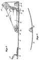
- FIGURE 1 is a plan view of a variable-camber airfoil incorporating variable-camber sections in the forward area of the wing;
- FIGURE 2 is a side elevation, cross-sectional view of the variable-camber airfoil taken along section line 2-2 of Figure 1 with the airfoil in a cruise, or minimum camber position;
- FIGURE 3 is a side elevation, cross-sectional view of the variable-camber airfoil of Figure 2 with the airfoil in a take-off or intermediate camber position;
- FIGURE 4 is a side elevation, cross-sectional view of the variable camber airfoil of Figure 2 with the airfoil in a landing or maximum camber position;
- FIGURE 5 is an enlarged side elevation, cross-sectional view of the flexible panel installed on the lower surface of the airfoil showing internal venting provisions;
- FIGURE 6 is a side elevation of the flexible panel showing the contour of the panel before it is mounted on the airfoil;
- FIGURE 7 is a cross-sectional view of the main drive arm taken along section line 7-7 of Figure 4;
- FIGURE 8 is a cross-sectional view of one link of the camber altering mechanism taken along section line 8-8 of Figure 4; and
- FIGURE 9 is a cross-sectional view of the stabilizing link of the camber altering mechanism taken along section line 9-9 of Figure 4.
- Referring to Figure 1, a variable-
camber airfoil 10 constructed in accordance with the present invention includes a leadingedge region 12 having a plurality offorward sections 14 that are adjacent one another. The camber offorward sections 14 can be altered to modify the lift characteristics ofairfoil 10. While the thickness offorward sections 14 varies in the spanwise direction, the mechanism and structural components used to alter the camber of each of theforward sections 14 is substantially identical. The apparatus shown in Figure 2, a cross-sectional view of oneforward section 14, is representative of the structure incorporated in each of theforward sections 14 and will be used for descriptive purposes throughout this disclosure. - Referring now to Figure 2, an enlarged cross-sectional view of a
forward section 14 is illustrated.Forward section 14 includes acamber altering mechanism 20 within thecavity 21 formed between the upper andlower surfaces forward section 14.Camber altering mechanism 20 is located forward of afront spar assembly 26 and rearward of a leadingedge nose structure 28.Camber altering mechanism 20 generally consists of a 4-bar linkage that is actuated by arotary actuator 30. By employingrotary actuator 30,camber altering mechanism 20 can smoothly and continuously moveforward section 14 between a first position (Figure 2) whereinairfoil 10 has a minimum camber and a second position (Figure 4) wherein the airfoil has a maximum camber. By positioning theforward section 14 at selected locations between the minimum and maximum camber positions, the camber ofairfoil 10 can be altered into a plurality ofconfigurations allowing airfoil 10 to efficiently satisfy a variety of flight modes. -
Forward section 14 will now be described in more detail in conjunction with Figures 2,3 and 4. Thefront spar assembly 26 is located at the rearmost area offorward section 14. Thefront spar assembly 26 includes a front spar 34 that extends spanwise the length ofairfoil 10. Front spar 34 generally has a "C" shaped configuration with anupper spar chord 36 and alower spar chord 38 that extend aft into thewing box 39 ofairfoil 10. The upper andlower spar chords oriented web 40. Asupport member 44 that acts as a mounting surface forrotary actuator 30 is mounted to front spar 34 and extends forwardly therefrom. The upper end ofsupport member 44 is fastened to theupper wing skin 46 through asplice plate 45. The lower end ofsupport member 44 is fastened tolower wing skin 47 through ashim 49. - The forward edge of the
upper wing skin 46 ofairfoil 10 lies in abutment with the rear edge of anupper panel 48. The aft end ofupper panel 48 abuts the upper surface ofsplice plate 45.Upper panel 48 extends forwardly fromatop splice plate 45 to a locationadjacent nose structure 28.Upper panel 48 if a flexible, continuous member with no breaks or joints in the chordwise direction, thus minimizing the aerodynamic drag generated by air flowing over theupper surface 22 ofairfoil 10. - The forward end of
upper panel 48 lies in abutment with the upper surface of a nose spar 50 that forms part ofnose structure 28.Nose spar 50 extends spanwise the length ofairfoil 10 and is generally "I" shaped with anupper flange 52 and alower flange 54 connected by aweb 56. Extending rearwardly fromnose spar 50 is a fitting 60. In the preferred embodiment,fitting 60 is a separate component that is fastened to the rear surface of nose spar 50 by means of rivets, bolts, or other conventional fastening means (not shown). Theupper portion 62 offitting 60 extends rearwardly in the chordwise direction and is used as an attachment point for members of thecamber altering mechanism 20, as will be described hereinafter. Fitting 60 also has asupport rib 64 extending rearwardly from the lower portion of the fitting that provides support for a portion oflower surface 24. Mounted in abutment with the forward surface ofnose spar 50 is a forwardly projectingnose rib 66 that forms the underlying structure for a leadingedge skin 70. The forward portion ofnose rib 66 has a parabolic shape when viewed in the spanwise direction to lend the desired aerodynamic shape to the leadingedge skin 70. - The leading
edge skin 70, which forms part ofnose structure 28, abuts the front edge ofupper panel 48 on top ofupper flange 52.Leading edge skin 70 wraps downwardly and forwardly around the parabolic curve of the forward portion ofnose rib 66 and continues rearward pastlower flange 54 of nose spar 50 to a point approximately midway betweennosespar 50 and front spar 34. A lower section of leadingedge skin 70 thus forms arigid panel 72 oflower surface 24.Rigid panel 72 is securely attached to supportrib 64 of fitting 60 by means of rivets, bolts, adhesives, or other conventional fastening means (not shown). In the embodiment shown, a short section ofrigid panel 72 extends rearward of the aft end ofsupport rib 64. Aflexible panel 74 oflower surface 24 is located rearward ofrigid panel 72 and extends rearwardly to a location adjacent the lower end offront spar assembly 26. - In the preferred embodiment,
flexible panel 74 is made from a flexible epoxy-fiberglass composite material.Flexible panel 74 is pivotally mounted to the forward end of alower mounting arm 76 that is integral with and extends forwardly from the lower portion ofsupport member 44.Flexible panel 74 pivots about apivot pin 78 that extends through apivot bracket 80 mounted to the inner surface of theflexible panel 74 and the forwardmost end oflower mounting arm 76. - The forward edge of
flexible panel 74 is positioned adjacent the rear edge ofrigid panel 72 as mentioned previously, with the inner surface of the forward end offlexible panel 74 abuting afront seal 86.Front seal 86 is fastened to the rear end ofsupport rib 64 and the rear edge of rigid panel 72 (Figure 5). The aft end offront seal 86 turns downwardly to form the contact area at which the inner surface offlexible panel 74 abuts the front seal. The inner surface of the aft end offlexible panel 74 abuts arear seal 88 and stopbracket 90 that are fastened to a continuousspanwise support channel 92 andsupport member 44. In the preferred embodiment,rear seal 88 has a "d" shape when viewed in the spanwise direction.Rear seal 88 is made from an elastomeric material so that it will deform when force is exerted against it. The lower end ofrear seal 88 extends below the lower end ofstop bracket 90 so that whenflexible panel 74 is in contact withstop bracket 90,rear seal 88 is compressed and forms an airtight seal againstflexible panel 74. - In the preferred embodiment, and as shown in Figure 6,
flexible panel 74 is formed with an upwardly directed concave configuration when viewed in a spanwise direction. Thus, whenflexible panel 74 is mounted on lower mountingarm 76 and forced into a substantially planar configuration, the forward and rear edges offlexible panel 74 are biased upwardly againstfront seal 86 and stopbracket 90, respectively, insuring thatflexible panel 74 remains in contact with the front seal and stop bracket as the camber ofairfoil 10 is altered. - Another feature of
flexible panel 74 involves the position ofpivot bracket 80. In a preferred embodiment,pivot bracket 80 is positioned onflexible panel 74 so that approximately forty percent (40%) of the chordwise dimension of the flexible panel is forward ofpivot bracket 80 and the remaining sixty percent (60%) of the panel is rearward of the pivot bracket. This placement ofpivot bracket 80 insures that a downward acting force arising from a build up of pressure incavity 21 will cause the aft end offlexible panel 74 to deflect open (as shown by the dashed line portion offlexible panel 74 in Figure 5) rather than the forward end, thereby allowing the increased pressure incavity 21 to be released. If the forward end offlexible panel 74 were deflected open, it would form a ram air scoop and increase the internal cavity pressure with possible damaging consequences. - As mentioned previously and as shown in Figures 2, 3, and 4,
rotary actuator 30 is mounted on the forward side ofsupport member 44 approximately midway between upper andlower surfaces main drive arm 94 is one of the links ofcamber altering mechanism 20 and is integrally mounted to a central portion ofrotary actuator 30 that rotates about a spanwise axis. Whenforward section 14 is in the first or cruise position (Figure 2),main drive arm 94 extends forward substantially parallel to a line that extends in a chordwise direction between the leading edge and trailing edge ofairfoil 10. Whenrotary actuator 30 is activated,main drive arm 94 moves through a downwardly and rearwardly directed path in a vertical chordwise plane relative to support member44. As shown in Figure 7,main drive arm 94 has a forked configuration with the forward portion ofmain drive arm 94 being comprised of spaced apart andparallel members 96 to receive linkage members therebetween. -
Camber altering mechanism 20 also includes a substantially planarfirst link 98 that is oriented in an upward and forward direction whenforward section 14 is in the cruise position (Figure 2). The lower end offirst link 98 is pivotally connected to the forwardmost end ofmain drive arm 94 betweenparallel members 96. The upper end offirst link 98 is pivotally connected toupper portion 62 of fitting 60 forward of the chordwise midpoint of the upper portion. The upper end offirst link 98 is located betweenparallel surfaces 100 ofupper portion 62. The upper and lowerends of first link98 are pivotally connected toupper portion 62 andmain drive arm 94, respectively, by self-aligning spherical bearings 102 (see generally Figure 7). - The use of
self aligning bearings 102 as pivots is typical for all of the pivoting connections incorporated in the linkage comprisingcamber altering mechanism 20. This type of pivotal connection allows some misalignment of the linkage components in a vertical plane without resulting in binding contact between the components when the linkage is actuated. - A substantially planar
second link 104 has its upper end pivotally connected to the rearmost end ofupper portion 62 and its lower end pivotally connected to approximately the midpoint ofmain drive arm 94. Whenforward section 14 is in the cruise position,second link 104 is oriented in an upward and forward direction. - Another member of
camber altering mechanism 20 is a stabilizinglink 106. Stabilizinglink 106 is oriented generally in a fore and aft direction whenforward section 14 is in the cruise position. The aft end of stabilizinglink 106 is pivotally connected to the forwardmost end of anupper mounting arm 108 that is integral withsupport member 44 and extends forwardly therefrom. Upper mountingarm 108 is comprised ofparallel arms 110 that are parallel to one another and spaced apart a distance sufficient to accept the aft end of stabilizinglink 106. The forward end of stabilizinglink 106 is pivotally mounted to approximately the midpoint ofsecond link 104. As shown in Figure 9, the forward portion of stabilizinglink 106 has a clevis- like configuration witharms 112 that are parallel to one another and spaced apart a distance sufficient to straddlesecond link 104. Once again, self-aligningspherical bearings 102 are used at each end of stabilizinglink 106 to connect the stabilizing link to the other linkage members. - The final member included in
camber altering mechanism 20 is apanel support link 116 connecting stabilizinglink 106 to asupport stringer 118 that is mounted spanwise on the inner surface ofupper panel 48. Panel support link 166 helps to control the contour of and provide support forupper panel 48 as the camber offorward section 14 is altered.Support stringer 118 has an inwardly extendinggusset 120 that is configured of parallel plates spaced apart in the spanwise direction. The upper end ofpanel support link 116 fits between the plates ofgusset 120 and is connected thereto by a self-aligning spherical bearing (not shown). The lower end ofpanel support link 116 is located betweenarms 112 of stabilizinglink 106 at approximately the midpoint of the stabilizing link as shown in Figure 9, and is pivotally connected thereto by another self-aligningspherical bearing 102. - The kinematic solution provided by the linkage system of
camber altering mechanism 20 in one that does not induce tension or compression loads intoupper panel 48 other than those due to the bending of the upper panel. Therefore, the fatigue life ofupper panel 48 will be the fatigue life expected for a panel subjected to pure bending loads. - To alter the camber of
airfoil 10,forward section 14 is moved from a first or cruise position (Figure 2) whereinairfoil 10 has minimum camber to a second or "landing" position (Figure 4) whereinairfoil 10 has maximum camber by activatingrotary actuator 30. Whenrotary actuator 30 is activated,main drive arm 94 moves downwardly and rearwardly through its arcuate path as shown in Figures 3 and 4. Asmain drive arm 94 moves downwardly, it pulls downwardly on first andsecond links panel link 116, which, due to the kinetic arrangement of the links, causesnose structure 28 and fitting 60 to move downwardly and rearwardly. Whennose structure 28 moves downwardly and rearwardly, the curvature ofupper panel 48 increases. In the embodiment shown, theleading edge 122 ofairfoil 10 is rotated approximately 30° asforward section 14 moves from the cruise to the landing position. - As
forward section 14 moves toward the landing position,rigid panel 72 moves rearwardly in sliding contact with the forward edge offlexible panel 74 as shown in Figures 3 and 4, forcing the forward edge downward. The contact points between the surface of rigid panel 72 -and the forward edge offlexible panel 74 are in constant engagement, producing a smooth substantially break free contour oflower surface 24 since the rear edge offlexible panel 74 remains in contact withstop bracket 90 andrear seal 88. Since the forward and rearward edges offlexible panel 74 are biased upwardly as previously described, the forward edge offlexible panel 74 remains in contact withrigid panel 72.
Claims (7)
Applications Claiming Priority (1)
| Application Number | Priority Date | Filing Date | Title |
|---|---|---|---|
| PCT/US1982/001822 WO1984002691A1 (en) | 1982-12-30 | 1982-12-30 | Variable-camber airfoil |
Publications (2)
| Publication Number | Publication Date |
|---|---|
| EP0130983A1 EP0130983A1 (en) | 1985-01-16 |
| EP0130983B1 true EP0130983B1 (en) | 1987-10-21 |
Family
ID=22168497
Family Applications (1)
| Application Number | Title | Priority Date | Filing Date |
|---|---|---|---|
| EP83901268A Expired EP0130983B1 (en) | 1982-12-30 | 1982-12-30 | Variable-camber airfoil |
Country Status (4)
| Country | Link |
|---|---|
| US (1) | US4553722A (en) |
| EP (1) | EP0130983B1 (en) |
| DE (1) | DE3277502D1 (en) |
| WO (1) | WO1984002691A1 (en) |
Cited By (1)
| Publication number | Priority date | Publication date | Assignee | Title |
|---|---|---|---|---|
| EP3020629A1 (en) | 2014-11-14 | 2016-05-18 | Airbus Defence and Space GmbH | Method for constructing a kinematic lever, use of same and related computer programm product |
Families Citing this family (38)
| Publication number | Priority date | Publication date | Assignee | Title |
|---|---|---|---|---|
| US6019312A (en) * | 1995-01-26 | 2000-02-01 | Blenn; Jesse | Airship tail fin construction for improved control |
| JPH09254893A (en) * | 1996-03-25 | 1997-09-30 | Commuter Herikoputa Senshin Gijutsu Kenkyusho:Kk | Rotor blade and rotor system for helicopter |
| US6318070B1 (en) * | 2000-03-03 | 2001-11-20 | United Technologies Corporation | Variable area nozzle for gas turbine engines driven by shape memory alloy actuators |
| US6720687B2 (en) * | 2000-12-22 | 2004-04-13 | General Electric Company | Wake reduction structure for enhancing cavity flow in generator rotor endwindings |
| KR100383919B1 (en) * | 2001-01-15 | 2003-05-14 | 주식회사 엘지화학 | Preparation of 2-(2-hydro xyphenyl)-2h-benzotriazoles |
| US7258308B2 (en) * | 2002-07-02 | 2007-08-21 | The Boeing Company | Method and apparatus for controlling airflow with a gapped trailing edge device having a flexible flow surface |
| US6796534B2 (en) † | 2002-09-10 | 2004-09-28 | The Boeing Company | Method and apparatus for controlling airflow with a leading edge device having a flexible flow surface |
| US7059563B2 (en) | 2003-06-03 | 2006-06-13 | The Boeing Company | Systems, apparatuses, and methods for moving aircraft control surfaces |
| US6799739B1 (en) | 2003-11-24 | 2004-10-05 | The Boeing Company | Aircraft control surface drive system and associated methods |
| US7229049B2 (en) * | 2004-05-04 | 2007-06-12 | Lockheed Martin Corporation | Unitized rotary actuator hinge fitting |
| US6978971B1 (en) | 2004-06-15 | 2005-12-27 | The Boeing Company | Methods and apparatuses for controlling airflow proximate to engine/airfoil systems |
| US7494094B2 (en) | 2004-09-08 | 2009-02-24 | The Boeing Company | Aircraft wing systems for providing differential motion to deployable lift devices |
| US7264206B2 (en) | 2004-09-30 | 2007-09-04 | The Boeing Company | Leading edge flap apparatuses and associated methods |
| US7338018B2 (en) | 2005-02-04 | 2008-03-04 | The Boeing Company | Systems and methods for controlling aircraft flaps and spoilers |
| US7721999B2 (en) | 2005-05-20 | 2010-05-25 | The Boeing Company | Aerospace vehicle fairing systems and associated methods |
| DE102005027749B4 (en) | 2005-06-16 | 2011-07-28 | Airbus Operations GmbH, 21129 | Buoyancy-enhancing flap, in particular nose flap, for an aerodynamically effective wing |
| US7367530B2 (en) | 2005-06-21 | 2008-05-06 | The Boeing Company | Aerospace vehicle yaw generating systems and associated methods |
| US7475854B2 (en) | 2005-11-21 | 2009-01-13 | The Boeing Company | Aircraft trailing edge devices, including devices with non-parallel motion paths, and associated methods |
| US7708231B2 (en) | 2005-11-21 | 2010-05-04 | The Boeing Company | Aircraft trailing edge devices, including devices having forwardly positioned hinge lines, and associated methods |
| US7954769B2 (en) | 2007-12-10 | 2011-06-07 | The Boeing Company | Deployable aerodynamic devices with reduced actuator loads, and related systems and methods |
| US7766282B2 (en) | 2007-12-11 | 2010-08-03 | The Boeing Company | Trailing edge device catchers and associated systems and methods |
| US8256719B2 (en) * | 2008-12-01 | 2012-09-04 | The Boeing Company | Shape changing airfoil system |
| US8226048B2 (en) | 2008-12-09 | 2012-07-24 | The Boeing Company | Link mechanisms, including Stephenson II link mechanisms for multi-position flaps and associated systems and methods |
| US8500060B2 (en) * | 2009-02-10 | 2013-08-06 | The Boeing Company | Aircraft with a pressurized vessel |
| US8056865B2 (en) | 2009-03-05 | 2011-11-15 | The Boeing Company | Mechanism for changing the shape of a control surface |
| GB0908370D0 (en) * | 2009-05-15 | 2009-06-24 | Airbus Uk Ltd | A hinge sealing element and an assembly including said element |
| DE102009026457A1 (en) | 2009-05-25 | 2010-12-09 | Eads Deutschland Gmbh | Aerodynamic component with deformable outer skin |
| US8382045B2 (en) | 2009-07-21 | 2013-02-26 | The Boeing Company | Shape-changing control surface |
| US8650811B2 (en) | 2011-02-04 | 2014-02-18 | The Boeing Company | Solar collector frame |
| US8925870B1 (en) * | 2012-03-09 | 2015-01-06 | The Boeing Company | Morphing wing leading edge |
| GB201222308D0 (en) * | 2012-12-11 | 2013-01-23 | Airbus Operations Ltd | Support assembly |
| US9598167B2 (en) | 2014-03-04 | 2017-03-21 | The Boeing Company | Morphing airfoil leading edge |
| US9896190B1 (en) * | 2014-05-07 | 2018-02-20 | The Boeing Company | Wing leading edge architecture suitable for laminar flow |
| US9415856B2 (en) * | 2014-06-04 | 2016-08-16 | The Boeing Company | Dual-rib morphing leading edge |
| DE102015105298B4 (en) * | 2015-04-08 | 2021-12-23 | Deutsches Zentrum für Luft- und Raumfahrt e.V. | Wing structure for flying objects and method for replacing a leading edge of a wing in a wing structure |
| GB201522486D0 (en) * | 2015-12-21 | 2016-02-03 | Airbus Operations Ltd | Seal assembly |
| EP4063257A1 (en) * | 2021-03-23 | 2022-09-28 | Airbus Operations GmbH | Wing for an aircraft |
| EP4063258A3 (en) * | 2021-03-23 | 2023-02-22 | Airbus Operations GmbH | Wing for an aircraft |
Family Cites Families (15)
| Publication number | Priority date | Publication date | Assignee | Title |
|---|---|---|---|---|
| US1567531A (en) * | 1923-03-24 | 1925-12-29 | Magni Piero | Variable fluido-dynamic wings such as for aeroplanes |
| FR574500A (en) * | 1923-12-15 | 1924-07-11 | Airplane wing with variable airfoil | |
| US1803915A (en) * | 1928-12-11 | 1931-05-05 | Parmele William Ray | Wing construction for aeroplanes |
| US1745677A (en) * | 1929-06-24 | 1930-02-04 | Hopper Mack Kinley | Aeroplane wing |
| US1747637A (en) * | 1929-10-31 | 1930-02-18 | Alf N Larsen | Adjustable aeroplane wing |
| US2010549A (en) * | 1933-10-18 | 1935-08-06 | Joseph Mandelbaum J | Aeroplane wing |
| US3836099A (en) * | 1973-09-28 | 1974-09-17 | Us Navy | Airfoil camber change system |
| US3994452A (en) * | 1974-03-28 | 1976-11-30 | The Boeing Company | Variable camber airfoil |
| US3994451A (en) * | 1974-03-28 | 1976-11-30 | The Boeing Company | Variable camber airfoil |
| US4040579A (en) * | 1975-08-25 | 1977-08-09 | The United States Of America As Represented By The Secretary Of The Navy | Variable camber leading edge airfoil system |
| GB1596642A (en) * | 1977-04-06 | 1981-08-26 | British Aerospace | Aircraft wings |
| US4171787A (en) * | 1977-07-21 | 1979-10-23 | Zapel Edwin J | Variable camber leading edge for airfoil |
| DE2907912C2 (en) * | 1979-03-01 | 1985-06-05 | Dornier Gmbh, 7990 Friedrichshafen | Transverse drive body with variable profiling, in particular nose parts of aircraft wings |
| US4351502A (en) * | 1980-05-21 | 1982-09-28 | The Boeing Company | Continuous skin, variable camber airfoil edge actuating mechanism |
| US4427168A (en) * | 1981-09-29 | 1984-01-24 | The Boeing Company | Variable camber leading edge mechanism with Krueger flap |
-
1982
- 1982-12-30 WO PCT/US1982/001822 patent/WO1984002691A1/en active IP Right Grant
- 1982-12-30 US US06/491,951 patent/US4553722A/en not_active Expired - Fee Related
- 1982-12-30 DE DE8383901268T patent/DE3277502D1/en not_active Expired
- 1982-12-30 EP EP83901268A patent/EP0130983B1/en not_active Expired
Cited By (1)
| Publication number | Priority date | Publication date | Assignee | Title |
|---|---|---|---|---|
| EP3020629A1 (en) | 2014-11-14 | 2016-05-18 | Airbus Defence and Space GmbH | Method for constructing a kinematic lever, use of same and related computer programm product |
Also Published As
| Publication number | Publication date |
|---|---|
| DE3277502D1 (en) | 1987-11-26 |
| US4553722A (en) | 1985-11-19 |
| EP0130983A1 (en) | 1985-01-16 |
| WO1984002691A1 (en) | 1984-07-19 |
Similar Documents
| Publication | Publication Date | Title |
|---|---|---|
| EP0130983B1 (en) | Variable-camber airfoil | |
| US4650140A (en) | Wind edge movable airfoil having variable camber | |
| US4120470A (en) | Efficient trailing edge system for an aircraft wing | |
| US4351502A (en) | Continuous skin, variable camber airfoil edge actuating mechanism | |
| US7258308B2 (en) | Method and apparatus for controlling airflow with a gapped trailing edge device having a flexible flow surface | |
| US4200253A (en) | Aircraft wing drooping leading edge device | |
| US5158252A (en) | Three-position variable camber Krueger leading edge flap | |
| US4015787A (en) | Aircraft wing | |
| US3987983A (en) | Trailing edge flaps having spanwise aerodynamic slot opening and closing mechanism | |
| US4171787A (en) | Variable camber leading edge for airfoil | |
| US7243881B2 (en) | Multi-function trailing edge devices and associated methods | |
| US4475702A (en) | Variable camber leading edge assembly for an airfoil | |
| JP3213752B2 (en) | Flaperon system for tilt rotor | |
| US8186630B2 (en) | Leading edge structure for an aerofoil | |
| US6598834B2 (en) | Method for reducing fuel consumption in aircraft | |
| EP0781704B1 (en) | Vortex leading edge flap assembly for supersonic airplanes | |
| US20100163685A1 (en) | Wing | |
| US6601801B1 (en) | Gapped trailing-edge control surface for an airfoil | |
| EP3524516B1 (en) | Linkage mechanism for linking a flaperon to a droop panel of an aircraft | |
| US2650047A (en) | Variable camber wing | |
| JPS647920B2 (en) | ||
| EP3423350B1 (en) | Edge morphing arrangement for an airfoil | |
| CN102171097A (en) | Fore flap disposed on the wing of an aircraft | |
| EP0103038A1 (en) | Continuous skin, variable camber airfoil edge actuating mechanism | |
| US6076775A (en) | Airfoil with a landing flap having a flexible trailing edge |
Legal Events
| Date | Code | Title | Description |
|---|---|---|---|
| PUAI | Public reference made under article 153(3) epc to a published international application that has entered the european phase |
Free format text: ORIGINAL CODE: 0009012 |
|
| 17P | Request for examination filed |
Effective date: 19840718 |
|
| AK | Designated contracting states |
Kind code of ref document: A1 Designated state(s): DE FR GB NL Designated state(s): DE FR GB NL |
|
| 17Q | First examination report despatched |
Effective date: 19860516 |
|
| GRAA | (expected) grant |
Free format text: ORIGINAL CODE: 0009210 |
|
| AK | Designated contracting states |
Kind code of ref document: B1 Designated state(s): DE FR GB NL |
|
| ET | Fr: translation filed | ||
| REF | Corresponds to: |
Ref document number: 3277502 Country of ref document: DE Date of ref document: 19871126 |
|
| PLBE | No opposition filed within time limit |
Free format text: ORIGINAL CODE: 0009261 |
|
| STAA | Information on the status of an ep patent application or granted ep patent |
Free format text: STATUS: NO OPPOSITION FILED WITHIN TIME LIMIT |
|
| 26N | No opposition filed | ||
| PGFP | Annual fee paid to national office [announced via postgrant information from national office to epo] |
Ref country code: NL Payment date: 19931231 Year of fee payment: 12 Ref country code: GB Payment date: 19931231 Year of fee payment: 12 |
|
| PGFP | Annual fee paid to national office [announced via postgrant information from national office to epo] |
Ref country code: FR Payment date: 19941228 Year of fee payment: 13 |
|
| PG25 | Lapsed in a contracting state [announced via postgrant information from national office to epo] |
Ref country code: GB Effective date: 19941230 |
|
| PG25 | Lapsed in a contracting state [announced via postgrant information from national office to epo] |
Ref country code: NL Effective date: 19950701 |
|
| GBPC | Gb: european patent ceased through non-payment of renewal fee |
Effective date: 19941230 |
|
| NLV4 | Nl: lapsed or anulled due to non-payment of the annual fee |
Effective date: 19950701 |
|
| PG25 | Lapsed in a contracting state [announced via postgrant information from national office to epo] |
Ref country code: FR Effective date: 19960830 |
|
| REG | Reference to a national code |
Ref country code: FR Ref legal event code: ST |
|
| PGFP | Annual fee paid to national office [announced via postgrant information from national office to epo] |
Ref country code: DE Payment date: 19970131 Year of fee payment: 15 |
|
| PG25 | Lapsed in a contracting state [announced via postgrant information from national office to epo] |
Ref country code: DE Free format text: LAPSE BECAUSE OF NON-PAYMENT OF DUE FEES Effective date: 19980901 |