EP0130701A2 - Improved comb-type bipolar stack and electrode assembly for a battery system having a circulating electrolyte - Google Patents
Improved comb-type bipolar stack and electrode assembly for a battery system having a circulating electrolyte Download PDFInfo
- Publication number
- EP0130701A2 EP0130701A2 EP84303701A EP84303701A EP0130701A2 EP 0130701 A2 EP0130701 A2 EP 0130701A2 EP 84303701 A EP84303701 A EP 84303701A EP 84303701 A EP84303701 A EP 84303701A EP 0130701 A2 EP0130701 A2 EP 0130701A2
- Authority
- EP
- European Patent Office
- Prior art keywords
- electrodes
- electrolyte
- electrode
- frame member
- battery system
- Prior art date
- Legal status (The legal status is an assumption and is not a legal conclusion. Google has not performed a legal analysis and makes no representation as to the accuracy of the status listed.)
- Granted
Links
Images


Classifications
-
- H—ELECTRICITY
- H01—ELECTRIC ELEMENTS
- H01M—PROCESSES OR MEANS, e.g. BATTERIES, FOR THE DIRECT CONVERSION OF CHEMICAL ENERGY INTO ELECTRICAL ENERGY
- H01M4/00—Electrodes
-
- H—ELECTRICITY
- H01—ELECTRIC ELEMENTS
- H01M—PROCESSES OR MEANS, e.g. BATTERIES, FOR THE DIRECT CONVERSION OF CHEMICAL ENERGY INTO ELECTRICAL ENERGY
- H01M10/00—Secondary cells; Manufacture thereof
- H01M10/36—Accumulators not provided for in groups H01M10/05-H01M10/34
- H01M10/365—Zinc-halogen accumulators
-
- Y—GENERAL TAGGING OF NEW TECHNOLOGICAL DEVELOPMENTS; GENERAL TAGGING OF CROSS-SECTIONAL TECHNOLOGIES SPANNING OVER SEVERAL SECTIONS OF THE IPC; TECHNICAL SUBJECTS COVERED BY FORMER USPC CROSS-REFERENCE ART COLLECTIONS [XRACs] AND DIGESTS
- Y02—TECHNOLOGIES OR APPLICATIONS FOR MITIGATION OR ADAPTATION AGAINST CLIMATE CHANGE
- Y02E—REDUCTION OF GREENHOUSE GAS [GHG] EMISSIONS, RELATED TO ENERGY GENERATION, TRANSMISSION OR DISTRIBUTION
- Y02E60/00—Enabling technologies; Technologies with a potential or indirect contribution to GHG emissions mitigation
- Y02E60/10—Energy storage using batteries
-
- Y—GENERAL TAGGING OF NEW TECHNOLOGICAL DEVELOPMENTS; GENERAL TAGGING OF CROSS-SECTIONAL TECHNOLOGIES SPANNING OVER SEVERAL SECTIONS OF THE IPC; TECHNICAL SUBJECTS COVERED BY FORMER USPC CROSS-REFERENCE ART COLLECTIONS [XRACs] AND DIGESTS
- Y02—TECHNOLOGIES OR APPLICATIONS FOR MITIGATION OR ADAPTATION AGAINST CLIMATE CHANGE
- Y02P—CLIMATE CHANGE MITIGATION TECHNOLOGIES IN THE PRODUCTION OR PROCESSING OF GOODS
- Y02P70/00—Climate change mitigation technologies in the production process for final industrial or consumer products
- Y02P70/50—Manufacturing or production processes characterised by the final manufactured product
Definitions
- the present invention relates generally to electrochemical systems, and particularly to an improved cell design in a metal-halogen battery stack.
- Electrochemical devices or systems of the type referred to herein include one or more of the metal-halogen battery systems, such as a zinc-chloride battery system.
- These metal-halogen battery systems generally are comprised of three basic components, namely an electrode stack section, an electrolyte circulation subsystem, and a store subsystem.
- the electrode stack section typically includes a plurality of cells connected together electrically in various series and parallel combinations to achieve a desired operating voltage and current at the battery terminals over a charge/discharge battery cycle.
- Each cell is comprised of a positive and negative electrode which are both in contact with an aqueous metalhalide electrolyte.
- the electrolyte circulation subsystem operates to circulate the metalhalide electrolyte from a reservoir through each of the cells in the electrode stack in order to replenish the metal and halogen electrolyte ionic components as they are oxidized or reduced in the cells during the battery cycle.
- the storage subsystem is used to contain the halogen gas or liquid which is liberated from the cells during the charging of the battery system for subsequent return to the cells during the discharging of the battery system.
- chlorine gas is liberated from the positive electrodes of the cells and stored in the form of chlorine hydrate.
- Chlorine hydrate is a solid which is formed by the store subsystem in a process analogous to the process of freezing water were chlorine is included in the ice crystal.
- an electrolyte pump operates to circulate the aqueous zinc-chloride electrolyte from a reservoir to each of the positive or "chlorine" electrodes in the electrode stack.
- These chlorine electrodes are typically made of porous graphite, and the electrolyte passes through the pores of the chlorine electrodes into a space between the chlorine electrodes and the opposing negative or “zinc” electrodes. The electrolyte then flows up between the opposing electrodes or otherwise out of the cells in the electrode stack and back to the electrolyte reservoir or sump.
- chlorine gas is liberated or generated at the chlorine electrode.
- the chlorine gas is collected in a suitable conduit, and then mixed with a chilled liquid to form chlorine hydrate.
- a gas pump is typically employed to draw the chlorine gas from the electrode stack and mix it with the chilled liquid, (i.e., generally either zinc-chloride electrolyte or water).
- the chlorine hydrate is then deposited in a store container until the battery system is to be discharged.
- the chlorine hydrate is decomposed by permitting the store temperature to increase, such as by circulating a warm liquid through the store container.
- the chlorine gas thereby recovered is returned to the electrode stack via the electrolyte circulation subsystem, were it is reduced at the chlorine electrodes.
- the zinc metal is dissolved off of the zinc electrode substrates, and power is available at the battery terminals.
- the concentration of the electrolyte varies as a result of the electrochemical reactions occurring at the electrodes in the cells of the electrode stack.
- the concentration of zinc-chloride in the aqueous electrolyte may typically be 2.0 molar.
- the electrolyte concentration will gradually decrease with the depletion of zinc and chloride ions from the electrolyte.
- the electrolyte concentration will typically be reduced to 0.5 molar. Then, as the battery system is discharged, the electrolyte concentration will gradually swing upwardly and return to the original 2.0 molar concentration when the battery system is completely or fully discharged.
- the present invention is directed to an improved comb-type bipolar cell and battery stack design. Specifically, it is a principal objective in an exemplary embodiment of the present invention to provide an improved cell design which is based upon flat plate electrodes (i.e., electrodes not having a contoured face).
- An improved cell design which incorporates low-cost electrode frames that feature integral masking of both the interior and exterior of the positive and negative electrodes.
- An improved cell design which incorporates low-cost electrode frames which features an electrolyte feed tube providing a controlled flow of electrolyte to the positive electrodes.
- An improved unit cell and battery stack design which provides for a controlled flow of electrolyte that is uniform to all positive electrodes within the battery stack.
- An improved electrode frame design which physically supports electrodes placed therein so as to prevent electrode bowing and to maintain the desired inter-electrode gap.
- An improved unit cell and battery stack design having excellent hydraulic integrity and ionic cell-to-cell isolation.
- An improved cell design which is capable of filtering the electrolyte flow to a plurality of cells connected electrically in parallel.
- a cell design which incorporates a substantially closed compartment which controls both the electrolyte flow to and from a plurality of cells.
- the above electrode assembly can be incorporated into a comb-type bipolar cell design which ionically isolates adjacent cells which are connected electrically in series. Such ionic isolation is important,in achieving uniform coulombic efficiency for each of the cells connected electrically in series.
- This cell design also features a housing or compartment means having a top section which includes manifold means for controlling both the electrolyte flow into and out of each series connected cell.
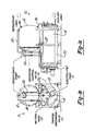
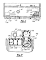
- FIGS. 1A and 1B two elevation views of a zinc-chloride battery system 10 in accordance with the present invention are shown.
- the various components of the battery system 10 are housed by two interconnected cylindrical vessels 12 and 14, which may best be illustrated by the schematic diagram of Figure 2.
- the upper vessel or case 12 is used to contain the chlorine hydrate store subsystem generally designated by reference numeral 16.
- the lower vessel or case 14 is used to contain both the battery stack 18 and the electrolyte circulation subsystem generally designated by reference numeral 20.
- the cylindrical vessels 12 and 14 are supported by a battery rack structure 22.
- the vessels 12 and 14 are preferably made from fiberglass-reinforced plastic (FRP) with an internal polyvinyl chloride (PVC) liner bonded thereto which is chemically resistant or inert to the electrolyte and the other chemical entities present within these vessels.
- FRP fiberglass-reinforced plastic
- PVC polyvinyl chloride
- the vessels 12 and 14 are interconnected by four fluid exchange lines or conduits 24, 26, 28 and 30, and the direction of fluid flow through these lines are indicated by the appropriate arrows.
- the battery system 10 is provided with four refrigerant lines or conduits 32, 34, 36 and 38.
- Refrigerant lines 32 and 34 are used to supply a coolant to the store subsystem 16 during the charging of the battery system for reducing the temperature inside vessel 12 to the appropriate level to form chlorine hydrate.
- Refrigerant lines 36 and 38 are used to supply a coolant to the sump or electrolyte reservoir 40 of the electrolyte circulation subsystem 20 to control the temperature of the zinc-chloride electrolyte.
- the electrolyte circulation subsystem 20 includes an ovate electrolyte pump "P1" which is mounted to the front end cap 42 of the bottom vessel 14 below the electrolyte level in the sump 40.
- the electrolyte pump Pl is driven by an electric motor 44 which is magnetically coupled to the electrolyte pmp.
- the electrolyte pump 42 is preferably of the centrifugal type manufactured by Ingersoll-Rand.
- the electrolyte pump 42 is adapted to draw electrolyte from the sump 40 through a titanium protective screen filter 46, and discharge the electrolyte axially through a slip joint 48 into a unique center-feed electrolyte distribution manifold 50.
- the manifold 50 is used to distribute electrolyte to each of the unit cells in the pair of submodules 52 and 54 which comprise the battery stack 18.
- the manifold 50 not only uniformly distributes the electrolyte to each of the unit cells in the submodule 52 and 54, but also acts to control and suppress the flow of parasitic currents which flow in the electrolyte circulation subsystem.
- Parasitic currents are those electrical currents which flow in the conductive paths created by the network of electrolyte connections linking the cells.
- FIG 4 a schematic diagram of one embodiment of the electrolyte circulation subsystem 20 is shown, which particularly illustrates the flow of electrolyte through the manifold 50.
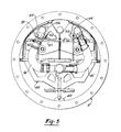
- Figure 5 illustrates a front end view of electrolyte circulation subsystem in association with the submodules 52 and 54
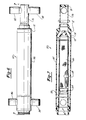
- Figures 6 and 7 which illustrate two views of the manifold 50.
- the manifold 50 includes a central portion 56 comprising a pair of concentric tubes, namely inner tube 58 and outer tube 60.
- Inner tube 58 is in fluid communication with the electrolyte pump Pl at a first end 62 thereof and includes an open opposite end 64 which is fitted with an in-line wire mesh electrolyte filter 66.
- Filter 66 includes a perforated protective outer jacket 68 and terminates at its distal end in a cap or plug 70. Electrolyte is pumped through inner tube 58 and passes out through filter 66 into outer tube 60. Outer tube 60 is fitted with an end cap 72 which includes a fluid conduit path 74 for conducting fluid around the inner end cap 70 and thence into conduit 76. Conduit 76 is sealed as at end plate 78 and includes a pair of fittings 80 and 82 for bifurcating the electrolyte fluid path. Similarly, outer tube 60 includes a pair of fittings 84 and 86 at the end adjacent electrolyte pump Pl for providing yet another bifurcated fluid path.
- Electrolyte is thus pumped out through filter 66 and into outer tube 60, whereupon half of the fluid is transmitted through tube 76 generally away from electrolyte pump P1, while the other half is transmitted through outer tube 60 generally toward electrolyte pump Pl.
- the electrolyte flow is again split into four distribution paths for feeding individually both left and right halves of the two submodules 52 and 54.
- the crossed inlet distribution tubes arrangement may now be explained. It will be seen in Figure 4 that, for example, the distribution tube 88, which is connected to fitting 82, feeds the left half 90 of submodule 54, the left half being physically more remote from fitting 82 than the right half 92. Similarly, fitting 86 is coupled via distribution tube 94 to the right half 92 of submodule 54.
- the electrical circuit path between left and right paths of submodule 54 are quite elongated and provide substantial resistance against parasitic current flow.
- parasitic current flow between unit cell feeder tubes 96 and 98 must travel the entire distance through tubes 88, fitting 82, tube 76, outer tube 60, fitting 86, and tube 94 in order to complete the shunt circuit.
- electrolyte pump Pl can be of a lower horsepower with a resultant improvement of the overall efficiency of the system.
- the outlet portion of the electrolyte circulation subsystem 20 in the embodiment of Figure 4 also employs the crossed outlet distribution tubes arrangement in order to increase the electrical resistance to parasitic current flow, in a similar manner as described above with respect to crossed inlet distribution tubes 88 and 94.
- the left and right halves of each submodule such as left and right halves 90 and 92 are cross-coupled to outlet tubes 100 and 102, respectively, in a fashion similar to the cross-coupled center feed inlet portion.
- the outlet portion of the electrolyte ciruclation subsystem 20 may employ a cascade canopy 104 as illustrated in Figures 3 and 5.
- each individual unit cell discharges through an outlet port 106 via discharge tube 108 and thence through orifices 110 onto the upper surface of the cascade canopy 104.
- the electrolyte then spills over the canopy 104, like rain water upon a shingled roof, spreading outwardly as it falls into sump 40, which improves the absorption of gaseous chlorine by the electrolyte during the discharge cycle.
- the manifold 50, the inlet crossed distribution tubes arangement and the outlet crossed collection tubes arrangement may broadly be viewed as different facets or building blocks of a more general principle or arrangement which may be called the center feed principle or arrangement, which is best explained by reference to prior art electrolyte distribution practices.
- electrolyte is typically delivered to each unit cell in a submodule comprised of series-connected unit cells via a common header, such a continuous substantially manifold or distribution tube having relatively low electrolyte resistance from one end of the header to the other.
- This end feed arrangement allows relatively large parasitic currents to develop in virtually every inter-cell shunt circuit in the submodule.
- the electrolyte distribution system illustrated in Figure 4 delivers electrolyte to a single submodule (such as submodule 54 for example) composed of series-connected unit cells by splitting the electrolyte flow in half, and delivering (or removing) each half-flow through a physically distinct header (for example tubes 60 and 76 in manifold 50, or inlet distribution tubes 88 and 94) having a relatively large resistance to parasitic current flow.
- a physically distinct header for example tubes 60 and 76 in manifold 50, or inlet distribution tubes 88 and 94
- the center feed arrangement may be said to encompass any electrolyte distribution scheme wherein the flow of electrolyte to a single submodule of series-connected unit cells is divided into two (or more) roughly equal portions and thereafter segregated for distribution (or collection) through two separate, electrically isolated headers having a relatively large electrical resistance wherein each header supplies electrolyte to (or collects electrolyte fran) a plurality of series-connected unit cells, and the parasitic currents caused by inter-cell shunt circuits between the separately fed portions of the submodule are substantially reduced relative to an end feed electrolyte distribution arrangement.
- the electrolyte circulation subsystem 20 of the battery system 10 disclosed herein was specifically designed so as to incorporate the foregoing center feed principle and to maximize the advantageous reduction in parasitic currents obtainable by utilizing a center feed arrangement.
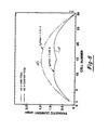
- Figure 8 is a graphical representation of typical shunt or parasitic current values displayed along the ordinate as a function of the cell number displayed along the abcissa.
- a battery having thirty unit cells connected electrically in series has been assumed, although it should be understood that the same advantageous results are obtainable in batteries having a different number of unit cells connected electrically in series.
- all of the cells in the battery are served by one electrolyte pump through a common supply and return manifolding.
- This common electrolyte manifolding provides an electrically conductive path through which current will pass when a voltage is present across the battery terminals and electrolyte circulation subsystem 20 including the battery stack is full of electrolyte.
- This shunt current reduces the effective current flowing through the cells during charge and causes cells in the battery to self discharge during discharge at different rates. In general, this results in faster depletion of zinc from the electrodes of cells in the center of the battery stack, and can cause measurable differences in the coulombic efficiency of cells within the battery stack.
- Figure 8 includes a curve 112 which represents the parasitic current distribution for a battery system having a prior art end-feed electrolyte distribution manifold, and a curve 114 which represents the parasitic current distribution for a battery system in accordance with the present invention having a center-feed electrolyte distribution manifold. It is important to note that the total parasitic current flow of curve 112 is not only greater than that for curve 114, but curve 114 indicates that the parasitic current distribution is considerably more uniform when the center-feed manifold is utilized.
- This benefit of the center-feed manifold is advantageous because it is not only desirable to minimize parasitic current flow, but is is also desirable to have a uniform distribution of the parasitic currents across the battery stack in order to achieve a substantially uniform coulombic efficiency for each of the unit cells in the battery stack.
- Electrode assembly 200 generally comprises a pair of porous graphite positive or chlorine electrodes 202 and 204, a dense graphite negative or zinc electrode 206, and plastic frame members 208 and 210.
- the positive electrodes 202 and 204 are adapted to slide into channels 212 and 214, respectively, in the frame member 208 such that the frame member supports these two electrodes along the top and bottom edges as well as along one of the side edges.
- the frame member 208 operates to align the positive electrodes 202 and 204 in parallel and provides an internal cavity between these electrodes.
- the frame member 208 is also formed to nestingly receive the frame member 210 between the positive electrodes 202 and 204.
- the frame member 210 includes a plastic-feed tube 216 for conveying electrolyte from a unit cell manifold to the internal cavity between the positive electrodes 202 and 204.
- the frame member 208 is also formed with a channel 218 which is adapted to receive a side edge of the negative electrode 206 and align the negative electrode 206 in parallel with the positive electrode 202. Accordingly, it will be appreciated that the frame member 208 serves to align and separate the positive electrodes 202 and 204 from each other, and also to align and separate the negative electrode 206 from the positive electrode 202.
- the separation between the negative electrode 206 and the positive electrode 202 is referred to as the inter-electrode gap which may generally range from about 40 mils (lmn) to about 250 mils (6mm) and is preferably about 129 mils (3.3mm).
- the frame member 208 also serves to control the edge effects of the positive electrodes 202 and 204 by providing an integral masking or screening around the edges of the positive electrodes in order to modify the electrochemical activity along these edges.
- the channels 212,214 and 218 are formed such that the apparent surface area of the positive electrodes is smaller in comparison with the apparent surface area of the negative electrodes.
- the frame member 208 includes an orifice 220 at the top thereof for venting any undissolved chlorine gas which could otherwise be trapped in the internal cavity between the positive electrodes 202 and 204. Additionally, the frame member 208 is formed with a pair of opposing, vertically extending spacing ribs 222 and 224. The ribs 222 and 224 restrain any tendency of the positive electrodes 202 and 204 to bow outwardly, and insure that the desired inter-electrode gap between the positive and negative electrodes is maintained. The integrity of this inter-electrode gap is important because it has been found that with increased gaps on the order of 129 mils the electrical current density for the battery system may be significantly increased. Also such increased gaps permit higher zinc loadings on the negative electrodes, which in turn means that substantial cost savings can be achieved through the reduction in the number of electrodes required to store an equivalent amount of electrical energy.
- the feed tube 216 of the electrode assembly 200 is press fit into a socket which is formed into an upwardly extending nipple portion 226 of the frame member 210. Additionally, the bottom end of the feed tube 216 is trapped between an upwardly extending clip portion 228 and the support channel portion 230 of the frame member 210. It should also be noted that the bottom end of the support channel portion 230 of the frame member 210 is shaped to mate with the bottom end of the internal separator portion 232 of the frame member 208. This contoured shaping at the bottom end operates in combination with a generally horizontally extending flange portion 234 of the frame member 210 at the top thereof to lock the frame member 210 to the frame member 208.
- the positive electrodes 202 and 204 be constructed from Union Carbide Corp. PG-60 or TS-1697 graphite, or Airco Carbon Co. S-1029 or S-1517 graphite.
- the negative electrode 206 it is preferred that this electrode be constructed from Union Carbide Corp. ECL grade graphite or alternative grades such as ATR or ATJ graphite herein.
- these components may be constructed from any suitable electrically nonconductive material which is chemically resistant or inert to the electrolyte and other chemical entities with which they will come into contact.
- frame members 208 and 210 be constructed fran General Tire and Rubber Corp.
- other suitable plastic materials may be employed such as Penwalt Kynar (R) (polyvinylidene fluoride) or any of the other appropriate materials described in Section 33 of The Development of the Zinc Chloride Battery For Utility Applications, April 1979 report identified earlier.
- the submodule 236 generally comprises a zinc termination comb assembly 238, a chlorine termination comb assembly 240, and one or more bipolar intermediate comb assemblies 242. While the submodule 236 is shown with only one intermediate comb assembly 242, it should be appreciated that the submodule may be expanded by merely providing for more intermediate comb assemblies. As shown in Figure 10, the submodule 236 includes two "unit" cells connected electrically in series. Each of these unit cells comprise a number of single cells (i.e., a positive electrode and an opposing negative electrode) connected electrically in parallel.
- the intermediate comb assembly 242 which may best be seen with reference to Figure 11, includes an electrically conductive bus member 244 (i.e. constructed from dense graphite) which has two generally planar opposing faces and a plastic frame 246 generally disposed around the edges of the bus member to provide an ionic seal between adjacent unit cells.
- Frame 246 is preferably formed by injection molding PVC about the edges of bus member 244.
- a pair of opposed longitudinally extending grooves 247 may be used to provide a mechanical interock between this PVC encapsulation and the edges of bus member 244.
- a plurality of positive electrode structures 248 are attached via a press or interference fit connection to one exterior face of the bus member 244, which is provided with spaced vertical grooves 249, while a plurality of negative electrodes 250 are attached to the other face of the bus member in a similar fashion.
- Each of the positive electrode structures 248 are constructed in accordance with the electrode assambly 200 of Figure 9, and include the positive electrodes 202 and 204, and the plastic frame members 208 and 210.
- a unit cell electrolyte distribution manifold 252 is ultrasonically welded or otherwise secured to the top section of each frame 246 such that electrolyte may be conveyed to the feed tubes 216.
- nipples 226 extending from the top of the frame members 210 are inserted through holes in the bottom tray 254 of the manifold 252. These nipples 226 are then welded by thermal swaging to the bottom tray 254 of the manifold 252 to provide a leak-proof connection.
- a plastic tray 256 as shown in Figure 10 is welded or otherwise secured to the bus bar frame 246 in a fluid tight connection.
- a return path for the electrolyte supplied to each of the unit cells is provided by a collection cup 258 and a discharge serpentine channel plate 260 which are adapted to receive the electrolyte flowing from the unit cell and direct this electrolyte to the reservoir or sump.
- the collection cup 258 and the discharge serpentine channel plate 260 are welded or otherwise secured (such as by solvent bonding) to the tray 256 in a fluid tight connection.
- the unit cell distribution manifold 252 also includes a top cover 262 which is secured to the bottom tray 254 by welding or solvent bonding.
- An important feature of the manifold 252 is the provision of a plastic perforated screen 264 which extends along the complete length of the manifold between the bottom tray 254 and the top cover 262.
- the perforations in the screen 264 are selected to be suitably smaller than the diameter of the opening in the nipples 226 of the frame member 210, so that any particles which could plug or obstruct fluid flow through the feed tubes 216 will be filtered by the screen 264.
- the screen 264 is preferably constructed from Kynar ( R ) and is preferably bent over in a generally U-shape.
- manifold 252 is also be provided with a suitable orifice 265 (shown in Figure 12) for permitting any gas which could otherwise be trapped in the manifold to escape.
- a suitable orifice 265 shown in Figure 12
- the location of orifices 265 near the outside edges of the unit cell also assures that sufficient electrolyte flow will occur adjacent the outermost electrodes of the unit cell.
- the aforementioned plastic components 252 through 264 are shown in an assembled state with reference to the chlorine termination comb assembly 240.
- the chlorine termination comb assembly 240 is similar in construction to the intermediate comb assembly 242 except that the chlorine termination comb assembly is not provided with a plurality of negative electrodes 250 along one face of the bus bar 244.
- the chlorine termination comb assembly 240 includes a plurality of electrical terminals mounted to the bus bar 244 to facilitate external electrical connections to the submodule 236. These electrical terminals, generally designated by reference numeral 266, are illustrated with reference to the zinc termination comb assembly 238.
- the zinc termination comb assembly 238 simply comprises a bus bar whose edges and external face are enclosed in a plastic frame and a plurality of negative electrodes attached on the internal face thereof.
- the positive electrode structures 248 of the intermediate comb assembly 242 will be interdigitated with the negative electrodes 250 of the zinc termination comb assembly 238, and the negative electrodes 250 of the intermediate comb assembly 242 will be interdigitated with the positive electrode structures 248 of the chloride termination comb assembly 240. Accordingly, the positive electrode structures 248 of the intermediate comb assembly 242 and the negative electrodes 250 of the zinc termination comb assembly 238 will form one unit cell, and the negative electrodes 250 of the intermediate comb assembly 242 and the positive electrode structures 248 of the chlorine termination comb assembly 240 will form the other unit cell of the submodule 236.
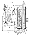
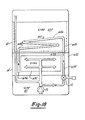
- FIG 12 a cutaway perspective view of the "closed" submodule 54 for the battery stack 18 of Figures 2 and 3 is shown.
- the construction of the submodule 54 is similar to the submodule 236 of Figure 10 in several respects.
- the principal difference between these two submodules is that the submodule 236 is generally open at the top thereof to allow chlorine gas (as well as any other gases) to be liberated from the unit cells; whereas, the submodule 54 is generally closed at the top thereof to control the flow of fluid from unit cells.
- the submodule 54 is comprised of twenty-four units cells connected electrically in series. These unit cells are generally designated by reference 300.
- FIG. 13 several views of the zinc termination unit cell 300 for the submodule 54 are shown, which particularly illustrate the plastic top section 310 thereof.
- the top section is welded or otherwise sealably secured to a three sided tray section 311 to form a substantially closed compartment for the unit cell.
- the top section 310 includes a supply port 312 which is connected to electrolyte distribution tube 88 via a unit cell feed tube 313.
- a similar electrolyte connection may best be seen with reference to Figure 3, which shows the supply port 314 of a unit cell 316 of the submodule 52 connected to the electrolyte distribution tube 318 via a feed tube 320.
- the top section 310 of the unit cell 300 also includes an outlet port 322 which is connected to the cascade canopy 324 via an outlet tube 326.
- the top section further includes a generally horizontally extending top wall 328 which is integrally formed with a downwardly extending serpentine partition portion 330.
- the serpentine partition portion 330 is used to form a serpentine-channel discharge manifold 332 in combination with a bottom cover plate 334 which is secured thereto in a generally fluid tight seal.
- the opening 336 of the discharge manifold permits chlorine gas and electrolyte to flow out of the unit cell 300 as may best be seen with reference to Figure 16.
- the top section 310 of the unit cell 300 additionally includes a unit cell feed manifold 338, which is generally comprised of a top cover 340 and a bottom tray 342 secured thereto in fluid tight relationship.
- the top cover 340 includes an upper cylindrical portion 344 which is adapted to extend through an orifice in the top wall 328 of the top section 310.
- the supply port 312 is adapted to slide over and be secured to the cylindrical portion 344.
- the top cover is also formed with elongated, downwardly extending partition portions 346 and 348 which direct the flow of electrolyte through the manifold 338 in cooperation with the bottom tray 342. Interposed between the top cover 340 and the bottom tray is a screen 350 for filtering the flow of electrolyte to the unit cell 300.
- the bottom tray 342 is formed with a plurality of holes 352 through which the nipples 226 of electrode frames 208 extend in order to be welded to the bottom tray and permit electrolyte flow to the internal cavities between the chlorine or positive electrodes 202 and 204.
- the electrolyte circulation sybsystem 20 of the battery system 10 is comprised of myriad large and small manifolds, serpentines and various size distribution tudes, all of which have been sized to present raher low hydraulic resistance to the amount of elecrolyte designed to flow therethrough in comparison to relatively high hydraulic resistance to flow presented by each feed tube 216 (see Figure 9) in the battery stack 18.
- the unit cell 300 is also shown to include a gas relief valve 354 which is secured to the top wall 328 in a fluid tight relationship.
- the relief valve 354 is used to selectively vent gas from the interior compartment of the unit cell 300 in response to the electrolyte level in the unit cell.
- the relief valve 354 is advantageously used to vent any hydrogen gas which may be present in the unit cell compartment when the battery system 10 is in a charge standby mode.
- the relief valve 354 is generally comprised of a conical-shaped housing 356 having a roughly cone-shaped hollow interior 357, and a buoyant float member 358.
- the housing 356 is formed with an orifice 360 at its top end for venting gas, and the relief valve 354 is formed at its bottom end with a pair of tang members 362 and 364 (which may best be seen in Figure 16) for mechanically locking the relief valve to the top wall 328 in a snap-fit connection.
- the float member 358 is shaped to generally conform to the interior surface 366 of the housing 356, so that the float member will block the flow of fluid from the unit cell compartment when the float member is moved upwardly into sealing engagement with the housing by the pressure exerted on the float member by the electrolyte.
- the float member 358 is also formed with an upwardly extending stem portion 368 for guiding the upward movement of the float member into sealing engagement with the housing 356. Since the float member 358 preferably has a hollow interior, a bottom plate 370 is bonded to the cylindrical portion of the float member in order to trap a quantity of air therein. It should also be noted that while the top wall 328 of the unit cell compartment is provided with an orifice 372 for communicating fluid to the relief valve 354, the orifice is made suitably smaller than the diameter of the float member 358 in order to prevent the float member from dropping into the discharge manifold 332 when the electrolyte level is low. Nevertheless, the orifice 372 must also be suitably shaped so as to permit venting even when the float member 358 has dropped to the point where it is resting upon the top wall 328.
- the discharge manifolds 332 for each of the unit cells 300 will become filled with electrolyte and cause the float members 358 to move upwardly to the point were the float members 358 seal the orifices 360. Then, when the battery system is switched to a standby mode, for example at the end of charge or discharge, the electrolyte pump Pl will be turned off and electrolyte circulation will cease. This will cause the electrolyte level in the discharge manifolds 332 to drop to a point sufficient to re-open the orifices 360 by the downward movement of the float members 358.
- the re-opening at the orifices 360 will permit any gas present in the discharge manifolds 332 or in the gas space between the plates 334 and the tops of the electrode frame members 208 to be vented from the unit cell compartments through the relief valves 354.
- This automatic venting provision is especially important when the battery system 10 is placed in a standby mode after the battery system has been charged, as it will permit any hydrogen gas evolved at the zinc or negative electrodes 206 during this time to be vented from the unit cell compartments.
- the relief valve 354 is designed, through an appropriate choice of size and density for the float member 358, so as to not permit capillary attraction or surface tension of the electrolyte to hold the buoyant float member 358 up in sealing engagement with the housing 356 after electrolyte circulation has ceased.
- FIGS 3 and 5 also illustrate a plastic sled 400 which is used to support the submodules 52 and 54 in the lower vessel 14. After the submodules 52 and 54 have been fully assembled with the various electrolyte distribution and collection components described above connected thereto, the sled 400 is then slid into the vessel 14 along an elongated rail 402.
- Figure 3 also illustrates the electrical connections which are made to the submodules 52 and 54.
- a set of four power terminals 404 are provided such that one power terminal is connected to each end of the submodules 52 and 54.
- Each of these power terminals comprise a titanium clad copper rod 406 which is friction welded to a titanium bar 408.
- the titanium bars 408 are attached to the plurality of terminal posts 410 provided at each end of the submodules 52 and 54.
- the power terminals 404 are then preferably encased in a plastic (liquid potting resin) envelope that extends outside of the vessel 14.
- the free ends of the power terminals 404 may then be connected to a suitable D.C. power source for charging the battery system 10 or a suitable load for discharging the battery system.
- Figure 3 also illustrates a glass tube 412 which is used to house a suitable ultraviolet light source, shown in phantom at reference numeral 414.
- the glass tube 412 is adapted to extend outside of the vessel 14 to facilitate replacement of the ultraviolet light source 414.
- the ultraviolet light source is adapted to react any hydrogen gas which may be present in the gas space in the vessel 14 with chlorine gas to form hydrogen chloride.
- the interaction between the store subsysten 16 of the vessel 12 and the battery stack 18 and electrolyte circulation subsystem 20 of vessel 14 will now be briefly described.
- the battery stack 18 will generate a continuous supply of chlorine gas.
- the chlorine gas will be drawn from the vessel 14 to the vessel 12 by the gas/hydrate pump "P2" via conduit 26.
- the pump P2 will then mix the chlorine gas with a chilled liquid (preferably water) in the vessel 12 to form chlorine hydrate.
- valve “Vl” will be opened to permit warm electrolyte from the sump 40 to be pumped through the hydrate decomposition heat exchanger "HX2" located in vessel 12 via conduits 28 and 30.
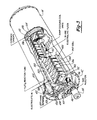
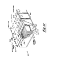
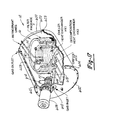
- FIG 17 is a cutaway perspective view showing the equipment arrangement inside the store subsystem 16 depicted in Figures 1 and 2.
- Store 16 is contained within a short cylindrical case or vessel 12 and is preferably mounted above the stack vessel 14 as shown in Figure 1.
- Vessel 12 has an integral domed end 600 and is closed with a domed cover 602 at the other end which is bolted to flange 604.
- vessel 12 is filled almost entirely with liquid (preferably water), leaving a relatively small gas space 605 best shown by liquid level line 606 in Figure 2.
- Components located within or on the store vessel 12 include gas/hydrate pump P2, filter package F, pressure control orifice 622, hydrate former heat exchanger BXl, and decomposition heat exchanger HX2. Various features and operating characteristics of these components may now be described.
- Gas/hydrate pump P2 with its electric driving motor 608 attached is mounted on boss 610 of domed cover 602.
- Pump P2 is of "plug-in" style construction with the motor armature magnetically-coupled to the pump shaft through a plastic pump cover 612, so that no motor or pump shaft projects through the wall of store vessel 12.
- the pump P2 is an external or spur gear type pump manufactured by Ingersoll-Rand and built with plastic gears and housings and graphite bushings.
- Pump P2 discharges through conical nozzle 614 directly into the gas space 605 at the top of vessel 12.
- Suction portion 616 of pump P2 plugs or couples directly into inlet fitting or coupling 618 rigidly mounted within the vessel 12.
- Gas from battery stack 18 provided via conduit 26 and liquid from the store 16 are fed into pump P2 through coupling 618.
- Chilled liquid (preferably water) is drawn through the coiled tube-in-tube heat exchanger HX1 from the liquid or water reservoir 620 of vessel 12.
- Filter F is configured as a double-called cylinder and subnierged in water reservoir 620.
- Filter F is constructed of a heavy-gauge PVC mesh on a rigid ring-like plastic frame, and covered with a sleeve of Teflon-felted cloth, which effectively prevents any hydrate crystals from entering the space between the cylinder walls of filter F.
- Heat exchanger HX1 Water enters heat exchanger HX1 from the space between the cylinder walls of filter F through an orifice 622 sized to allow the desired liquid flow rate and maintain the internal pressure within heat exchanger HX1 at approximately suction pressure of pump P2, which is preferably about 11 psia.
- Heat exchanger HX1 is a simple tube-in-tube assembly, which preferably consists of two concentric titanium tubes rolled to form a coil 624 as shown in Figure 17.
- High-flux coating commercially available from Union Carbide Corporation, is preferably deposited on the outer surface of the inner tube to drastically reduce the superheat required for refrigerant boiling by promoting nucleate boiling, thus effectively increasing the heat transfer coefficient from two to ten-fold. Use of such a coating allows heat exchanger HX1 to be made more compact than otherwise would be possible.
- Refrigerant used in heat exchanger HX1 is preferably Freon 12, and is provided through refrigerant supply and return lines 32 and 34, which are shown passing through the domed end 600 of store vessel 12 by way of pressure-tight sealed bushings. As shown in Figures 2 and 17, refrigerant flows through the annulus portion of coil 624 of heat exchanger HX1, while the store liquid flows through the inner tube of coil 624.
- the equipment packaged inside store vessel 12 is preferably mounted on a self-locating support frame or sled (not shown) contoured to rest upon the curved inner eurface of the vessel.
- a support frame allows heat exchangers HX1 and HX2, package filter F, pressure control orifice 622, and the pump inlet coupling 618 to be erected outside of store vessel 12 so that they may be slipped inside as a complete assembly.
- the equipment packaged inside the store vessel 12 can then be held stationary with respect to store vessel 12 by various attachments of the equipnent to the store vessel 12 such as the bushings for the two refrigerant lines 32 and 34 and the two bushings for lines 28 and 30 going to heat exchanger HX2 (see Figures 2 and 19).
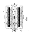
- decomposition heat exchangers HX2 shown in Figures 17, 19 and 20 are formed by bending a length of tubing (preferably 1/2 or 5/8 inch O.D. titanium tubing) into the desired shape or pattern.
- the coil pattern selected for the heat exchanger HX2 should allow electrolyte to drain from the heat exchanger HX2 when not in use.
- Figures 19 and 20 show two preferred coil patterns for heat exchanger HX2 designed to ensure such proper drainage. Experience has shown, for example, that even the generally horizontal coil pattern for heat exchanger HX2 shown in Figure 17 does not effectively provide complete drainage of electrolyte from heat exchanger HX2.
- the store vessel 12 itself is preferably made from FRP with a PVC liner bonded thereto. Since the temperature within store vessel 12 is preferably maintained at approximately ten degrees C, which may be below ambient temperatures typically encountered in indoor installations of the battery system, thermal insulation is preferably placed about much of the external surfaces of the store vessel to improve the overall system energy efficiency.
- a one and one-half inch layer of urethane foam designated by the numeral 628 covers approximately eighty percent of the exterior of vessel 12, and the foam in turn may be covered by a thin one-eighth inch of FRP lay-up to protect it from damage.
- a preferred electrolyte is a two molar concentration of zinc-chloride (measured when the battery system 10 is fully discharged), having supporting (i.e., conductivity-improving) salts of about a four molar concentration of potassium chloride and about a one molar concentration of sodium chloride to increase overall battery system efficiency.
- the electrolyte temperature in stack vessel 14 preferably maintained between about thirty and forty degrees C.
- Warm electrolyte from sump 40 continuously circulating through heat exchanger HX2 typically is not cooled during its passage through heat exchanger HX2 more than ten degrees C, and thus, precipitation of supporting salts in the electrolyte does not normally occur at the time.
- the zinc-chloride battery systems shown in the prior art have been redesigned so that the decomposition heat exchanger BX2 is now self-draining during those periods of time when no flow of electrolyte is required therethrough.
- the battery system 10 is now designed so that heat exchanger HX2 of the store subsystem 16 is located higher than the sump 40 associated with the battery stack 18, so that electrolyte will drain from heat exchanger HX2 back to the sump 40 when electrolyte flow therethrough is not required. This is preferably accomplished by placing store vessel 12 completely above stack vessel 14 as shown in the latest battery system designs in Figures 1, 2 and 20.
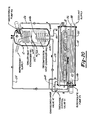
- FIG 18 is a schematic diagram of the self-draining heat exchanger concept with the store 630 elevated above the level of electrolyte in the sump 40.
- electrolyte pump PI provides electrolyte to the stack 632.
- pump P1 also provides electrolyte to beat exchanger HX2 through conduit 634 by opening decomposition control valve V1, which is normally closed during all other times of the battery cycle.
- decomposition control valve V1 which is normally closed during all other times of the battery cycle.
- the rate at which heat is provided to the liquid in store 630 by heat exchanger HX2 determines the rate at which chlorine is liberated by the decomposition of chlorine hydrate in the store.
- Control valve Vl may be intermittently opened and closed during the discharge mode to modulate this heat transfer rate.
- vent means 638 has been added between the outlet of pump Pl and the inlet 640 of heat exchanger HX2 to allow gas to enter heat exchanger HX2 to replace electrolyte as it drains therefrom.
- the gas is preferably drawn, as shown in Figure 18, from the gas space 642 of stack vessel 14.
- vent 638 must be placed downstream from the control valve Vl.
- Vent means 638 in the preferred embodiment of the zinc-chloride battery system of the present invention is a 1/16 inch diameter hole in conduit 634, and is connected to gas space 642 in stack vessel 14.
- a larger or smaller size hole could be used for the vent 638. While a 1/32 inch hole could be used for example, a 1/16 inch hole is deemed preferable since it is deemed less susceptible to clogging by any small particulate or foreign matter which might possibly be present in the electrolyte.
- An advantage of a small hole, such as a 1/16 inch diameter hole, over a considerably large hole such as a 5/16 inch diameter hole, is that its liquid volumetric capacity is insignificant in comparison to the flow of electrolyte through the heat exchanger, so that any electrolyte flow through vent 638 back to the sump 40 represents a negligible energy loss to the battery system. Yet, the gaseous volumetric capacity of the vent 638 for such a small hole is sufficiently large to ensure fairly rapid drainage of the electrolyte from heat exchanger HX2 before the electrolyte therein cools sufficiently to allow any significant precipitation of conductivity-improving salts.
- FIGS 18, 19 and 20 show that a heat exchanger HX2 of the eelf-draining type is preferably constructed of three parts: an inlet portion 640, an outlet portion 644, and a generally helical central portion 646 disposed between the inlet and outlet portions.
- Central portion 646 preferably slopes substantially continuously downward from the inlet portion 640 to the outlet portion 644 in order to prevent any electrolyte from remaining in the central portion of heat exchanger HX2 when the electrolyte is to be drained therefran.
- the angle of the slope may be varied so long as it is sufficient both to prevent electrolyte from remaining within heat exchanger HX2, and to allow relatively quick drainage of the electrolyte before it cools sufficiently to allow any significant precipitation.
- heat exchanger HX2 The optimal slope and configuration of heat exchanger HX2 is dependent upon the roan available therefor in store vessel 12, the size and length of the tubing used therefor, the length of the conduit inter connections between the heat exchanger and the sump 40 and electrolyte pump Pl, and the size of the hole or orifice for the vent 638. Variations in all of these design details are within the contemplated scope of the invention.
- Vent means 638 rather than being continuously open to the gas space as is shown in Figure 18, could alternatively be opened and closed as needed through the use of a control valve.
- a simple hole in conduit 634 is deemed preferable to using control valve approach to venting since such a vent hole is less costly, simpler, and inherently automatic in operation.
- conduit 634 may remain in conduit 634 between decomposition control valve V1 and vent 638. Because conduit 634 is outside of store vessel 12, and is therefore subject to much higher ambient temperatures, precipitation of salt therein is not a problem.
- Figures 1 and 2 show a preferred embodiment of vent 638 and piping therefor.
- decomposition control valve V1 and vent 638 which is shown schematically in Figure 2 as orifice 648, are located exterior to both store and stack vessels 12 and 14.
- the exterior location of conduit 24, 26, 28 and 30, valves V1 and V2, and vent 638, as well as other equipment shown in Figures 1 and 2, facilitate trouble-shooting, maintenance and repair of these items.
- Figures 19 and 20 each illustrate a preferred embodiment of an overall lay-out and coil pattern for a self-draining heat exchanger HX2. Tests of self-draining heat exchanger HX2 arrangement described above with respect to Figure 18 have shown it to be very effective in preventing precipitation of salts in heat exchanger HX2 and the clogging problem resulting therefrom.
- FIG 20 shows an alternative embodiment of the store subsystem that is being designed for large commercial installations such as electrical utility load-leveling applications.
- the principles of operation and construction techniques of the battery system shown in Figure 20 are basically the same as those shown for the battery system of Figure 1.
- the upright position of store vessel 12 in Figure 20, in conjunction with the reduction of the diameter of the store vessel to match the diameter of the stack vessel 14, provides a considerably more compact stacking arrangement for multiple battery systems used in large applications like a commercial load-leveling battery plant.
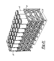
- One such compact stacking arrangement which beneficially provides a rather high battery system density per unit volume, is shown in Figure 21.
- each individual battery system shown in Figure 20 has its battery stack 18 within the stack vessel 14 increased from 72 inches (as shown in the battery stack of Figure 2) to 92 inches.
- other components such as the three heat exchangers HXl, HX2 and HX3 are increased in size to accomodate the increased energy capacity.
Abstract
Description
- The present invention relates generally to electrochemical systems, and particularly to an improved cell design in a metal-halogen battery stack.
- Electrochemical devices or systems of the type referred to herein include one or more of the metal-halogen battery systems, such as a zinc-chloride battery system. These metal-halogen battery systems generally are comprised of three basic components, namely an electrode stack section, an electrolyte circulation subsystem, and a store subsystem. The electrode stack section typically includes a plurality of cells connected together electrically in various series and parallel combinations to achieve a desired operating voltage and current at the battery terminals over a charge/discharge battery cycle. Each cell is comprised of a positive and negative electrode which are both in contact with an aqueous metalhalide electrolyte. the electrolyte circulation subsystem operates to circulate the metalhalide electrolyte from a reservoir through each of the cells in the electrode stack in order to replenish the metal and halogen electrolyte ionic components as they are oxidized or reduced in the cells during the battery cycle. In a closed, self-contained metal-halogen battery system, the storage subsystem is used to contain the halogen gas or liquid which is liberated from the cells during the charging of the battery system for subsequent return to the cells during the discharging of the battery system. In the zinc-chloride battery system, chlorine gas is liberated from the positive electrodes of the cells and stored in the form of chlorine hydrate. Chlorine hydrate is a solid which is formed by the store subsystem in a process analogous to the process of freezing water were chlorine is included in the ice crystal.
- With reference to the general operation of a zinc-chloride battery system, an electrolyte pump operates to circulate the aqueous zinc-chloride electrolyte from a reservoir to each of the positive or "chlorine" electrodes in the electrode stack. These chlorine electrodes are typically made of porous graphite, and the electrolyte passes through the pores of the chlorine electrodes into a space between the chlorine electrodes and the opposing negative or "zinc" electrodes. The electrolyte then flows up between the opposing electrodes or otherwise out of the cells in the electrode stack and back to the electrolyte reservoir or sump.
- During the charging of the zinc-chloride battery system, zinc metal is deposited on the zinc electrode substrates and chlorine gas is liberated or generated at the chlorine electrode. The chlorine gas is collected in a suitable conduit, and then mixed with a chilled liquid to form chlorine hydrate. A gas pump is typically employed to draw the chlorine gas from the electrode stack and mix it with the chilled liquid, (i.e., generally either zinc-chloride electrolyte or water). The chlorine hydrate is then deposited in a store container until the battery system is to be discharged.
- During the discharging of the zinc-chloride battery system, the chlorine hydrate is decomposed by permitting the store temperature to increase, such as by circulating a warm liquid through the store container. The chlorine gas thereby recovered is returned to the electrode stack via the electrolyte circulation subsystem, were it is reduced at the chlorine electrodes. Simultaneously, the zinc metal is dissolved off of the zinc electrode substrates, and power is available at the battery terminals.
- Over the course of the zinc-chloride battery charge/discharge cycle, the concentration of the electrolyte varies as a result of the electrochemical reactions occurring at the electrodes in the cells of the electrode stack. At the beginning of charge, the concentration of zinc-chloride in the aqueous electrolyte may typically be 2.0 molar. As the charging portion of the cycle progresses, the electrolyte concentration will gradually decrease with the depletion of zinc and chloride ions from the electrolyte. When the battery system is fully charged, the electrolyte concentration will typically be reduced to 0.5 molar. Then, as the battery system is discharged, the electrolyte concentration will gradually swing upwardly and return to the original 2.0 molar concentration when the battery system is completely or fully discharged.
- The present invention is directed to an improved comb-type bipolar cell and battery stack design. Specifically, it is a principal objective in an exemplary embodiment of the present invention to provide an improved cell design which is based upon flat plate electrodes (i.e., electrodes not having a contoured face).
- Preferred embodiments include the following features:
- An improved cell design which incorporates low-cost electrode frames that may be injection molded to enhance manufacturability and which facilitates assembly of the battery stack.
- An improved cell design which incorporates low-cost electrode frames that feature integral masking of both the interior and exterior of the positive and negative electrodes.
- An improved cell design which incorporates low-cost electrode frames which features an electrolyte feed tube providing a controlled flow of electrolyte to the positive electrodes.
- An improved unit cell and battery stack design which provides for a controlled flow of electrolyte that is uniform to all positive electrodes within the battery stack.
- An improved electrode frame design which physically supports electrodes placed therein so as to prevent electrode bowing and to maintain the desired inter-electrode gap.
- An improved unit cell and battery stack design having excellent hydraulic integrity and ionic cell-to-cell isolation.
- An improved cell design which is capable of filtering the electrolyte flow to a plurality of cells connected electrically in parallel.
- A cell design which incorporates a substantially closed compartment which controls both the electrolyte flow to and from a plurality of cells.
- The above electrode assembly can be incorporated into a comb-type bipolar cell design which ionically isolates adjacent cells which are connected electrically in series. Such ionic isolation is important,in achieving uniform coulombic efficiency for each of the cells connected electrically in series. This cell design also features a housing or compartment means having a top section which includes manifold means for controlling both the electrolyte flow into and out of each series connected cell.
- Additional advantages and features for the present invention will become apparent from a reading of the detailed description of the preferred embodiments which make reference to the following set of drawings, in which:
- Figure lA is a side elevation view of one embodiment of a zinc-chloride battery system according to the present invention.
- Figure 1B is a front elevation view of the battery system shown in Figure lA.
- Figure 2 is a schematic diagram of the battery system shown in Figures lA and B.
- Figure 3 is a cutaway perspective view of the stack and electrolyte circulation subsystems for the battery system shown in Figures 1 and 2.
- Figure 4 is a schematic diagram of the electrolyte circulation subsystem shown in Figures 2 and 3.
- Figure 5 is a front elevation view of the stack and electrolyte circulation subsystems shown in Figure 3 with the end cap removed.
- Figure 6 is a fragmentary plan view of the electrolyte distribution manifold for the electrolyte circulation subsystem.
- Figure 7 is a framentary cross-sectional view of the manifold shown in Figure 10 taken along lines 7-7.
- Figure 8 is a graph comparing parasitic current values associated with two electrolyte circulation schemes.
- Figure 9 is an exploded perspective view of an electrode assembly which forms the basic building block of the battery stack shown in Figures 2 and 3.
- Figure 10 is a fragmentary exploded view of an "open" submodule for a zinc-chloride battery stack.
- Figure 11 is a perspective view of a comb assembly employed in the submodule shown in Figure 10.
- Figure 12 is a cutaway perspective view of a *closed" submodule for the zinc-chloride battery stack shown in Figures 2 and 3.
- Figure 13 is a fragmentary top elevation view of the submodule shown in Figure 12.
- Figure 14 is a cross-sectional view of the submodule shown in Figure 13 taken along lines 14-14.
- Figure 15 is a cross-sectional view of the submodule shown in Figure 13 taken along lines 15-15.
- Figure 16 is a horizontal cross-sectional view of the submodule shown in Figure 13 taken along lines 16-16.
- Figure 17 is a cutaway perspective view of a store subsystem employing a conventional decomposition heat exchanger.
- Figure 18 is a schematic diagram of a self draining heat decomposition heat exchanger for a zinc-chloride battery system.
- Figure 19 is a cutaway perspective view of the store subsystem for the battery system shown in Figures 1 and 2.
- Figure 20 is an alternative embodiment of a zinc-chloride battery system according to the present invention.
- Figure 21 is a high density arrangement of a plurality of battery systems of the type shown in Figure 20.
- Referring to Figures 1A and 1B, two elevation views of a zinc-
chloride battery system 10 in accordance with the present invention are shown. The various components of thebattery system 10 are housed by two interconnectedcylindrical vessels case 12 is used to contain the chlorine hydrate store subsystem generally designated byreference numeral 16. The lower vessel orcase 14 is used to contain both thebattery stack 18 and the electrolyte circulation subsystem generally designated byreference numeral 20. - The
cylindrical vessels battery rack structure 22. Thevessels vessels conduits battery system 10 is provided with four refrigerant lines orconduits Refrigerant lines store subsystem 16 during the charging of the battery system for reducing the temperature insidevessel 12 to the appropriate level to form chlorine hydrate.Refrigerant lines electrolyte reservoir 40 of theelectrolyte circulation subsystem 20 to control the temperature of the zinc-chloride electrolyte. - Referring now to Figures 2 and 3, the
electrolyte circulation subsystem 20 will now be described. Theelectrolyte circulation subsystem 20 includes an ovate electrolyte pump "P1" which is mounted to thefront end cap 42 of thebottom vessel 14 below the electrolyte level in thesump 40. The electrolyte pump Pl is driven by anelectric motor 44 which is magnetically coupled to the electrolyte pmp. Theelectrolyte pump 42 is preferably of the centrifugal type manufactured by Ingersoll-Rand. Theelectrolyte pump 42 is adapted to draw electrolyte from thesump 40 through a titaniumprotective screen filter 46, and discharge the electrolyte axially through a slip joint 48 into a unique center-feedelectrolyte distribution manifold 50. - The manifold 50 is used to distribute electrolyte to each of the unit cells in the pair of
submodules battery stack 18. The manifold 50 not only uniformly distributes the electrolyte to each of the unit cells in thesubmodule - Referring to Figure 4, a schematic diagram of one embodiment of the
electrolyte circulation subsystem 20 is shown, which particularly illustrates the flow of electrolyte through the manifold 50. Reference may also be made to Figure 5 which illustrates a front end view of electrolyte circulation subsystem in association with thesubmodules central portion 56 comprising a pair of concentric tubes, namelyinner tube 58 andouter tube 60.Inner tube 58 is in fluid communication with the electrolyte pump Pl at a first end 62 thereof and includes an openopposite end 64 which is fitted with an in-line wiremesh electrolyte filter 66.Filter 66 includes a perforated protectiveouter jacket 68 and terminates at its distal end in a cap or plug 70. Electrolyte is pumped throughinner tube 58 and passes out throughfilter 66 intoouter tube 60.Outer tube 60 is fitted with anend cap 72 which includes afluid conduit path 74 for conducting fluid around the inner end cap 70 and thence into conduit 76. Conduit 76 is sealed as atend plate 78 and includes a pair offittings outer tube 60 includes a pair offittings filter 66 and intoouter tube 60, whereupon half of the fluid is transmitted through tube 76 generally away from electrolyte pump P1, while the other half is transmitted throughouter tube 60 generally toward electrolyte pump Pl. At fittings 80-82 and at fittings 84-86 the electrolyte flow is again split into four distribution paths for feeding individually both left and right halves of the two submodules 52 and 54. - With specific reference to Figure 4, the crossed inlet distribution tubes arrangement may now be explained. It will be seen in Figure 4 that, for example, the
distribution tube 88, which is connected to fitting 82, feeds theleft half 90 ofsubmodule 54, the left half being physically more remote from fitting 82 than theright half 92. Similarly, fitting 86 is coupled via distribution tube 94 to theright half 92 ofsubmodule 54. Hence the electrical circuit path between left and right paths ofsubmodule 54 are quite elongated and provide substantial resistance against parasitic current flow. For example, parasitic current flow between unitcell feeder tubes tubes 88, fitting 82, tube 76,outer tube 60, fitting 86, and tube 94 in order to complete the shunt circuit. Although the length of this shunt circuit is substantial and the electrical resistance is therefore high, the fluid circuit thus described including the crossedinlet distribution tubes 88 and 94 provides remarkably little burden on electrolyte pump Pl. Hence electrolyte pump Pl can be of a lower horsepower with a resultant improvement of the overall efficiency of the system. - The outlet portion of the
electrolyte circulation subsystem 20 in the embodiment of Figure 4 also employs the crossed outlet distribution tubes arrangement in order to increase the electrical resistance to parasitic current flow, in a similar manner as described above with respect to crossedinlet distribution tubes 88 and 94. With reference to Figure 4 it will be seen that the left and right halves of each submodule, such as left andright halves electrolyte ciruclation subsystem 20 may employ acascade canopy 104 as illustrated in Figures 3 and 5. In this alternative outlet arrangement each individual unit cell discharges through anoutlet port 106 viadischarge tube 108 and thence throughorifices 110 onto the upper surface of thecascade canopy 104. The electrolyte then spills over thecanopy 104, like rain water upon a shingled roof, spreading outwardly as it falls intosump 40, which improves the absorption of gaseous chlorine by the electrolyte during the discharge cycle. - The manifold 50, the inlet crossed distribution tubes arangement and the outlet crossed collection tubes arrangement may broadly be viewed as different facets or building blocks of a more general principle or arrangement which may be called the center feed principle or arrangement, which is best explained by reference to prior art electrolyte distribution practices. In prior art zinc-chloride battery system, electrolyte is typically delivered to each unit cell in a submodule comprised of series-connected unit cells via a common header, such a continuous substantially manifold or distribution tube having relatively low electrolyte resistance from one end of the header to the other. This end feed arrangement allows relatively large parasitic currents to develop in virtually every inter-cell shunt circuit in the submodule. In contrast, the electrolyte distribution system illustrated in Figure 4 delivers electrolyte to a single submodule (such as
submodule 54 for example) composed of series-connected unit cells by splitting the electrolyte flow in half, and delivering (or removing) each half-flow through a physically distinct header (forexample tubes 60 and 76 inmanifold 50, orinlet distribution tubes 88 and 94) having a relatively large resistance to parasitic current flow. Thus, in comparison to the large parasitic currents existing between the commonly fed halves of the submodule in the prior art and feed arrangements, all shunt circuits in Figure 4 existing between the separately fed (with electrolyte) halves of the submodule are dramatically reduced. Broadly speaking then the center feed arrangement may be said to encompass any electrolyte distribution scheme wherein the flow of electrolyte to a single submodule of series-connected unit cells is divided into two (or more) roughly equal portions and thereafter segregated for distribution (or collection) through two separate, electrically isolated headers having a relatively large electrical resistance wherein each header supplies electrolyte to (or collects electrolyte fran) a plurality of series-connected unit cells, and the parasitic currents caused by inter-cell shunt circuits between the separately fed portions of the submodule are substantially reduced relative to an end feed electrolyte distribution arrangement. Theelectrolyte circulation subsystem 20 of thebattery system 10 disclosed herein was specifically designed so as to incorporate the foregoing center feed principle and to maximize the advantageous reduction in parasitic currents obtainable by utilizing a center feed arrangement. - The effectiveness of the above-described center feed electrolyte distribution arrangement is exemplified by reference to Figure 8. Figure 8 is a graphical representation of typical shunt or parasitic current values displayed along the ordinate as a function of the cell number displayed along the abcissa. For illustration purposes a battery having thirty unit cells connected electrically in series has been assumed, although it should be understood that the same advantageous results are obtainable in batteries having a different number of unit cells connected electrically in series. As related above, all of the cells in the battery are served by one electrolyte pump through a common supply and return manifolding. This common electrolyte manifolding provides an electrically conductive path through which current will pass when a voltage is present across the battery terminals and
electrolyte circulation subsystem 20 including the battery stack is full of electrolyte. This shunt current reduces the effective current flowing through the cells during charge and causes cells in the battery to self discharge during discharge at different rates. In general, this results in faster depletion of zinc from the electrodes of cells in the center of the battery stack, and can cause measurable differences in the coulombic efficiency of cells within the battery stack. - Knowing the resistivity of the electrolyte and the sizes of different portions of the
electrolyte circulation subsystem 20, the effective electrical resistances of the various sections can be calculated. An equivalent electrical circuit model may then be constructed, if desired, in accordance with the teachings of U.S. Patent No. 4,371,825, issued on February 1, 1983 to Chi et al, entitled "Method Of Minimizing The Effects Of Parasitic Currents", which is hereby incorporated by reference. Figure 8 is a graph comparing parasitic current values during charging which were calculated from such an electrical circuit model. Figure 8 includes acurve 112 which represents the parasitic current distribution for a battery system having a prior art end-feed electrolyte distribution manifold, and a curve 114 which represents the parasitic current distribution for a battery system in accordance with the present invention having a center-feed electrolyte distribution manifold. It is important to note that the total parasitic current flow ofcurve 112 is not only greater than that for curve 114, but curve 114 indicates that the parasitic current distribution is considerably more uniform when the center-feed manifold is utilized. This benefit of the center-feed manifold is advantageous because it is not only desirable to minimize parasitic current flow, but is is also desirable to have a uniform distribution of the parasitic currents across the battery stack in order to achieve a substantially uniform coulombic efficiency for each of the unit cells in the battery stack. - Referring to Figure 9, an exploded view of a zinc-chloride
battery electrode assembly 200 is shown which forms the basic building block of thebattery stack 18.Electrode assembly 200 generally comprises a pair of porous graphite positive orchlorine electrodes 202 and 204, a dense graphite negative or zinc electrode 206, andplastic frame members positive electrodes 202 and 204 are adapted to slide intochannels 212 and 214, respectively, in theframe member 208 such that the frame member supports these two electrodes along the top and bottom edges as well as along one of the side edges. Theframe member 208 operates to align thepositive electrodes 202 and 204 in parallel and provides an internal cavity between these electrodes. Theframe member 208 is also formed to nestingly receive theframe member 210 between thepositive electrodes 202 and 204. - The
frame member 210 includes a plastic-feed tube 216 for conveying electrolyte from a unit cell manifold to the internal cavity between thepositive electrodes 202 and 204. Theframe member 208 is also formed with achannel 218 which is adapted to receive a side edge of the negative electrode 206 and align the negative electrode 206 in parallel with thepositive electrode 202. Accordingly, it will be appreciated that theframe member 208 serves to align and separate thepositive electrodes 202 and 204 from each other, and also to align and separate the negative electrode 206 from thepositive electrode 202. The separation between the negative electrode 206 and thepositive electrode 202 is referred to as the inter-electrode gap which may generally range from about 40 mils (lmn) to about 250 mils (6mm) and is preferably about 129 mils (3.3mm). - The
frame member 208 also serves to control the edge effects of thepositive electrodes 202 and 204 by providing an integral masking or screening around the edges of the positive electrodes in order to modify the electrochemical activity along these edges. Generally speaking, the channels 212,214 and 218 are formed such that the apparent surface area of the positive electrodes is smaller in comparison with the apparent surface area of the negative electrodes. A more detailed discussion of masking edge effects may be found in the commonly assigned Carr et al. U.S. Patent No. 4,241,150, entitled "Method for Control of Edge Effects of Oxidant Electrode", which is hereby incorporated by reference. - It should also be noted that the
frame member 208 includes anorifice 220 at the top thereof for venting any undissolved chlorine gas which could otherwise be trapped in the internal cavity between thepositive electrodes 202 and 204. Additionally, theframe member 208 is formed with a pair of opposing, vertically extendingspacing ribs ribs positive electrodes 202 and 204 to bow outwardly, and insure that the desired inter-electrode gap between the positive and negative electrodes is maintained. The integrity of this inter-electrode gap is important because it has been found that with increased gaps on the order of 129 mils the electrical current density for the battery system may be significantly increased. Also such increased gaps permit higher zinc loadings on the negative electrodes, which in turn means that substantial cost savings can be achieved through the reduction in the number of electrodes required to store an equivalent amount of electrical energy. - The
feed tube 216 of theelectrode assembly 200 is press fit into a socket which is formed into an upwardly extendingnipple portion 226 of theframe member 210. Additionally, the bottom end of thefeed tube 216 is trapped between an upwardly extendingclip portion 228 and the support channel portion 230 of theframe member 210. It should also be noted that the bottom end of the support channel portion 230 of theframe member 210 is shaped to mate with the bottom end of theinternal separator portion 232 of theframe member 208. This contoured shaping at the bottom end operates in combination with a generally horizontally extendingflange portion 234 of theframe member 210 at the top thereof to lock theframe member 210 to theframe member 208. - With respect to the materials which may be used to construct the
electrode assembly 200, it is preferred that thepositive electrodes 202 and 204 be constructed from Union Carbide Corp. PG-60 or TS-1697 graphite, or Airco Carbon Co. S-1029 or S-1517 graphite. With respect to the negative electrode 206, it is preferred that this electrode be constructed from Union Carbide Corp. ECL grade graphite or alternative grades such as ATR or ATJ graphite herein. With respect to theframe members tube 216, these components (as well as the other plastic components to be described below) may be constructed from any suitable electrically nonconductive material which is chemically resistant or inert to the electrolyte and other chemical entities with which they will come into contact. While it is preferred that theframe members tube 216 from DuPont Teflon (R) (polytetrafluoro-ethylene), other suitable plastic materials may be employed such as Penwalt Kynar (R) (polyvinylidene fluoride) or any of the other appropriate materials described in Section 33 of The Development of the Zinc Chloride Battery For Utility Applications, April 1979 report identified earlier. - Referring to Figure 10, an exploded view of an "open" submodule 236 for a zinc-chloride battery stack is shown. The
submodule 236 generally comprises a zinctermination comb assembly 238, a chlorinetermination comb assembly 240, and one or more bipolarintermediate comb assemblies 242. While thesubmodule 236 is shown with only oneintermediate comb assembly 242, it should be appreciated that the submodule may be expanded by merely providing for more intermediate comb assemblies. As shown in Figure 10, thesubmodule 236 includes two "unit" cells connected electrically in series. Each of these unit cells comprise a number of single cells (i.e., a positive electrode and an opposing negative electrode) connected electrically in parallel. - The
intermediate comb assembly 242, which may best be seen with reference to Figure 11, includes an electrically conductive bus member 244 (i.e. constructed from dense graphite) which has two generally planar opposing faces and aplastic frame 246 generally disposed around the edges of the bus member to provide an ionic seal between adjacent unit cells.Frame 246 is preferably formed by injection molding PVC about the edges ofbus member 244. A pair of opposed longitudinally extendinggrooves 247 may be used to provide a mechanical interock between this PVC encapsulation and the edges ofbus member 244. A plurality ofpositive electrode structures 248 are attached via a press or interference fit connection to one exterior face of thebus member 244, which is provided with spaced vertical grooves 249, while a plurality ofnegative electrodes 250 are attached to the other face of the bus member in a similar fashion. Each of thepositive electrode structures 248 are constructed in accordance with theelectrode assambly 200 of Figure 9, and include thepositive electrodes 202 and 204, and theplastic frame members electrolyte distribution manifold 252 is ultrasonically welded or otherwise secured to the top section of eachframe 246 such that electrolyte may be conveyed to thefeed tubes 216. Specifically, thenipples 226 extending from the top of theframe members 210 are inserted through holes in thebottom tray 254 of themanifold 252. Thesenipples 226 are then welded by thermal swaging to thebottom tray 254 of the manifold 252 to provide a leak-proof connection. - In order that each unit cell may be separately sealed, a
plastic tray 256 as shown in Figure 10 is welded or otherwise secured to thebus bar frame 246 in a fluid tight connection. A return path for the electrolyte supplied to each of the unit cells is provided by acollection cup 258 and a dischargeserpentine channel plate 260 which are adapted to receive the electrolyte flowing from the unit cell and direct this electrolyte to the reservoir or sump. As in the case of the other plastic frame members or components, thecollection cup 258 and the dischargeserpentine channel plate 260 are welded or otherwise secured (such as by solvent bonding) to thetray 256 in a fluid tight connection. - As illustrated in Figure 11, the unit
cell distribution manifold 252 also includes a top cover 262 which is secured to thebottom tray 254 by welding or solvent bonding. An important feature of the manifold 252 is the provision of a plasticperforated screen 264 which extends along the complete length of the manifold between thebottom tray 254 and the top cover 262. The perforations in thescreen 264 are selected to be suitably smaller than the diameter of the opening in thenipples 226 of theframe member 210, so that any particles which could plug or obstruct fluid flow through thefeed tubes 216 will be filtered by thescreen 264. Thescreen 264 is preferably constructed from Kynar (R) and is preferably bent over in a generally U-shape. It should also be noted that the manifold 252 is also be provided with a suitable orifice 265 (shown in Figure 12) for permitting any gas which could otherwise be trapped in the manifold to escape. The location oforifices 265 near the outside edges of the unit cell also assures that sufficient electrolyte flow will occur adjacent the outermost electrodes of the unit cell. - In Figure 10, the aforementioned
plastic components 252 through 264 are shown in an assembled state with reference to the chlorinetermination comb assembly 240. The chlorinetermination comb assembly 240 is similar in construction to theintermediate comb assembly 242 except that the chlorine termination comb assembly is not provided with a plurality ofnegative electrodes 250 along one face of thebus bar 244. However, the chlorinetermination comb assembly 240 includes a plurality of electrical terminals mounted to thebus bar 244 to facilitate external electrical connections to thesubmodule 236. These electrical terminals, generally designated byreference numeral 266, are illustrated with reference to the zinctermination comb assembly 238. The zinctermination comb assembly 238 simply comprises a bus bar whose edges and external face are enclosed in a plastic frame and a plurality of negative electrodes attached on the internal face thereof. In an assembled state, thepositive electrode structures 248 of theintermediate comb assembly 242 will be interdigitated with thenegative electrodes 250 of the zinctermination comb assembly 238, and thenegative electrodes 250 of theintermediate comb assembly 242 will be interdigitated with thepositive electrode structures 248 of the chloridetermination comb assembly 240. Accordingly, thepositive electrode structures 248 of theintermediate comb assembly 242 and thenegative electrodes 250 of the zinctermination comb assembly 238 will form one unit cell, and thenegative electrodes 250 of theintermediate comb assembly 242 and thepositive electrode structures 248 of the chlorinetermination comb assembly 240 will form the other unit cell of thesubmodule 236. - Referring to Figure 12, a cutaway perspective view of the "closed"
submodule 54 for thebattery stack 18 of Figures 2 and 3 is shown. The construction of thesubmodule 54 is similar to thesubmodule 236 of Figure 10 in several respects. The principal difference between these two submodules is that thesubmodule 236 is generally open at the top thereof to allow chlorine gas (as well as any other gases) to be liberated from the unit cells; whereas, thesubmodule 54 is generally closed at the top thereof to control the flow of fluid from unit cells. Thesubmodule 54 is comprised of twenty-four units cells connected electrically in series. These unit cells are generally designated byreference 300. - Referring additionally to Figures 13 through 16, several views of the zinc
termination unit cell 300 for the submodule 54 are shown, which particularly illustrate the plastictop section 310 thereof. The top section is welded or otherwise sealably secured to a threesided tray section 311 to form a substantially closed compartment for the unit cell. Thetop section 310 includes asupply port 312 which is connected to electrolytedistribution tube 88 via a unitcell feed tube 313. A similar electrolyte connection may best be seen with reference to Figure 3, which shows thesupply port 314 of aunit cell 316 of the submodule 52 connected to theelectrolyte distribution tube 318 via afeed tube 320. - The
top section 310 of theunit cell 300 also includes anoutlet port 322 which is connected to thecascade canopy 324 via anoutlet tube 326. As may best be seen with respect to Figure 14, the top section further includes a generally horizontally extendingtop wall 328 which is integrally formed with a downwardly extendingserpentine partition portion 330. Theserpentine partition portion 330 is used to form a serpentine-channel discharge manifold 332 in combination with abottom cover plate 334 which is secured thereto in a generally fluid tight seal. Theopening 336 of the discharge manifold permits chlorine gas and electrolyte to flow out of theunit cell 300 as may best be seen with reference to Figure 16. - The
top section 310 of theunit cell 300 additionally includes a unitcell feed manifold 338, which is generally comprised of atop cover 340 and abottom tray 342 secured thereto in fluid tight relationship. Thetop cover 340 includes an uppercylindrical portion 344 which is adapted to extend through an orifice in thetop wall 328 of thetop section 310. Thesupply port 312 is adapted to slide over and be secured to thecylindrical portion 344. The top cover is also formed with elongated, downwardly extendingpartition portions bottom tray 342. Interposed between thetop cover 340 and the bottom tray is ascreen 350 for filtering the flow of electrolyte to theunit cell 300. Thebottom tray 342 is formed with a plurality ofholes 352 through which thenipples 226 of electrode frames 208 extend in order to be welded to the bottom tray and permit electrolyte flow to the internal cavities between the chlorine orpositive electrodes 202 and 204. - Referring collectively to Figures 3, 4, 9-16, the uniformity of electrolyte distribution amongst all of the individual chlorine electrode pairs contained in
electrode assemblies 200 of thebattery system 10 may now be explained. As shown in the Figures just mentioned, theelectrolyte circulation sybsystem 20 of thebattery system 10 is comprised of myriad large and small manifolds, serpentines and various size distribution tudes, all of which have been sized to present raher low hydraulic resistance to the amount of elecrolyte designed to flow therethrough in comparison to relatively high hydraulic resistance to flow presented by each feed tube 216 (see Figure 9) in thebattery stack 18. On account of the foregoing design, there exists substantially equal hydraulic pressure in all unit cell manifolds 252 (see Figure 11) and in all serpentine-channel discharge manifolds of each submodule (see Figures 12 and 14), if not bothsubmodules feed tube 216 is substantially the same, and since all feedtubes 216 in thebattery stack 18 are of the same length and inner diameter, allelectrode assemblies 200 in each submodule experience substantially equal flow rates. - Similarly, since the flow capacities of all manifolds and distribution tubes in
electrolyte circulation subsystem 20 are relatively large in comparison to the flow rates they experience, the differential hydraulic pressure across any givenfeed tube 216, and therefore the electrolyte flow rate for theelectrode assembly 200 it supplies, remains substantially uniform over time while thebattery system 10 is charging or discharging. - Referring specifically now to Figure 15 the
unit cell 300 is also shown to include agas relief valve 354 which is secured to thetop wall 328 in a fluid tight relationship. Therelief valve 354 is used to selectively vent gas from the interior compartment of theunit cell 300 in response to the electrolyte level in the unit cell. In particular, therelief valve 354 is advantageously used to vent any hydrogen gas which may be present in the unit cell compartment when thebattery system 10 is in a charge standby mode. - The
relief valve 354 is generally comprised of a conical-shapedhousing 356 having a roughly cone-shaped hollow interior 357, and abuoyant float member 358. Thehousing 356 is formed with anorifice 360 at its top end for venting gas, and therelief valve 354 is formed at its bottom end with a pair oftang members 362 and 364 (which may best be seen in Figure 16) for mechanically locking the relief valve to thetop wall 328 in a snap-fit connection. Thefloat member 358 is shaped to generally conform to theinterior surface 366 of thehousing 356, so that the float member will block the flow of fluid from the unit cell compartment when the float member is moved upwardly into sealing engagement with the housing by the pressure exerted on the float member by the electrolyte. Thefloat member 358 is also formed with an upwardly extendingstem portion 368 for guiding the upward movement of the float member into sealing engagement with thehousing 356. Since thefloat member 358 preferably has a hollow interior, abottom plate 370 is bonded to the cylindrical portion of the float member in order to trap a quantity of air therein. It should also be noted that while thetop wall 328 of the unit cell compartment is provided with anorifice 372 for communicating fluid to therelief valve 354, the orifice is made suitably smaller than the diameter of thefloat member 358 in order to prevent the float member from dropping into thedischarge manifold 332 when the electrolyte level is low. Nevertheless, theorifice 372 must also be suitably shaped so as to permit venting even when thefloat member 358 has dropped to the point where it is resting upon thetop wall 328. - When the electrolyte is being circulated through the
battery system 10, such as during the charging or discharging of the battery system, thedischarge manifolds 332 for each of theunit cells 300 will become filled with electrolyte and cause thefloat members 358 to move upwardly to the point were thefloat members 358 seal theorifices 360. Then, when the battery system is switched to a standby mode, for example at the end of charge or discharge, the electrolyte pump Pl will be turned off and electrolyte circulation will cease. This will cause the electrolyte level in the discharge manifolds 332 to drop to a point sufficient to re-open theorifices 360 by the downward movement of thefloat members 358. The re-opening at theorifices 360 will permit any gas present in thedischarge manifolds 332 or in the gas space between theplates 334 and the tops of theelectrode frame members 208 to be vented from the unit cell compartments through therelief valves 354. This automatic venting provision is especially important when thebattery system 10 is placed in a standby mode after the battery system has been charged, as it will permit any hydrogen gas evolved at the zinc or negative electrodes 206 during this time to be vented from the unit cell compartments. It should also be noted that therelief valve 354 is designed, through an appropriate choice of size and density for thefloat member 358, so as to not permit capillary attraction or surface tension of the electrolyte to hold thebuoyant float member 358 up in sealing engagement with thehousing 356 after electrolyte circulation has ceased. - Referring to Figures 3 and 5, these Figures also illustrate a
plastic sled 400 which is used to support thesubmodules lower vessel 14. After thesubmodules sled 400 is then slid into thevessel 14 along anelongated rail 402. - Figure 3 also illustrates the electrical connections which are made to the
submodules power terminals 404 are provided such that one power terminal is connected to each end of thesubmodules copper rod 406 which is friction welded to atitanium bar 408. The titanium bars 408 are attached to the plurality ofterminal posts 410 provided at each end of thesubmodules submodules power terminals 404 are then preferably encased in a plastic (liquid potting resin) envelope that extends outside of thevessel 14. The free ends of thepower terminals 404 may then be connected to a suitable D.C. power source for charging thebattery system 10 or a suitable load for discharging the battery system. - Figure 3 also illustrates a
glass tube 412 which is used to house a suitable ultraviolet light source, shown in phantom atreference numeral 414. Theglass tube 412 is adapted to extend outside of thevessel 14 to facilitate replacement of the ultravioletlight source 414. The ultraviolet light source is adapted to react any hydrogen gas which may be present in the gas space in thevessel 14 with chlorine gas to form hydrogen chloride. - Referring again to Figure 2, the interaction between the store subsysten 16 of the
vessel 12 and thebattery stack 18 andelectrolyte circulation subsystem 20 ofvessel 14 will now be briefly described. when thebattery system 10 is in a charge mode, thebattery stack 18 will generate a continuous supply of chlorine gas. The chlorine gas will be drawn from thevessel 14 to thevessel 12 by the gas/hydrate pump "P2" viaconduit 26. The pump P2 will then mix the chlorine gas with a chilled liquid (preferably water) in thevessel 12 to form chlorine hydrate. when the battery is in a discharge mode, valve "Vl" will be opened to permit warm electrolyte from thesump 40 to be pumped through the hydrate decomposition heat exchanger "HX2" located invessel 12 viaconduits vessel 12 will then be transmitted back to thevessel 14 viaconduit 24. This supply of chlorine gas is then injected into theelectrolyte circulation subsystem 20 where the gas is dissolved in the electrolyte which is being distributed to thebattery stack 18. At the end of discharge, all of the chlorine hydrate will have been decomposed and the chlorine gas returned and consumed in thebattery stack 18. - Figure 17 is a cutaway perspective view showing the equipment arrangement inside the
store subsystem 16 depicted in Figures 1 and 2.Store 16 is contained within a short cylindrical case orvessel 12 and is preferably mounted above thestack vessel 14 as shown in Figure 1.Vessel 12 has an integraldomed end 600 and is closed with adomed cover 602 at the other end which is bolted to flange 604. In operation,vessel 12 is filled almost entirely with liquid (preferably water), leaving a relativelysmall gas space 605 best shown byliquid level line 606 in Figure 2. - Components located within or on the
store vessel 12 include gas/hydrate pump P2, filter package F,pressure control orifice 622, hydrate former heat exchanger BXl, and decomposition heat exchanger HX2. Various features and operating characteristics of these components may now be described. - Gas/hydrate pump P2 with its
electric driving motor 608 attached is mounted onboss 610 ofdomed cover 602. Pump P2 is of "plug-in" style construction with the motor armature magnetically-coupled to the pump shaft through aplastic pump cover 612, so that no motor or pump shaft projects through the wall ofstore vessel 12. The pump P2 is an external or spur gear type pump manufactured by Ingersoll-Rand and built with plastic gears and housings and graphite bushings. - Pump P2 discharges through
conical nozzle 614 directly into thegas space 605 at the top ofvessel 12. Suction portion 616 of pump P2 plugs or couples directly into inlet fitting orcoupling 618 rigidly mounted within thevessel 12. Gas frombattery stack 18 provided viaconduit 26 and liquid from thestore 16 are fed into pump P2 throughcoupling 618. Chilled liquid (preferably water) is drawn through the coiled tube-in-tube heat exchanger HX1 from the liquid orwater reservoir 620 ofvessel 12. - In order that hydrate crystals, also slurried in
water reservoir 620, not be drawn through heat exchanger BXl and pump P2, a eeparation leaf-type filter package "F' is employed. Filter F is configured as a double-called cylinder and subnierged inwater reservoir 620. Filter F is constructed of a heavy-gauge PVC mesh on a rigid ring-like plastic frame, and covered with a sleeve of Teflon-felted cloth, which effectively prevents any hydrate crystals from entering the space between the cylinder walls of filter F. - Water enters heat exchanger HX1 from the space between the cylinder walls of filter F through an
orifice 622 sized to allow the desired liquid flow rate and maintain the internal pressure within heat exchanger HX1 at approximately suction pressure of pump P2, which is preferably about 11 psia. - Heat exchanger HX1, as shown in a number of the accompanying drawings, is a simple tube-in-tube assembly, which preferably consists of two concentric titanium tubes rolled to form a
coil 624 as shown in Figure 17. High-flux coating, commercially available from Union Carbide Corporation, is preferably deposited on the outer surface of the inner tube to drastically reduce the superheat required for refrigerant boiling by promoting nucleate boiling, thus effectively increasing the heat transfer coefficient from two to ten-fold. Use of such a coating allows heat exchanger HX1 to be made more compact than otherwise would be possible. - Refrigerant used in heat exchanger HX1 is preferably
Freon 12, and is provided through refrigerant supply and returnlines domed end 600 ofstore vessel 12 by way of pressure-tight sealed bushings. As shown in Figures 2 and 17, refrigerant flows through the annulus portion ofcoil 624 of heat exchanger HX1, while the store liquid flows through the inner tube ofcoil 624. - The equipment packaged inside
store vessel 12 is preferably mounted on a self-locating support frame or sled (not shown) contoured to rest upon the curved inner eurface of the vessel. Such a support frame allows heat exchangers HX1 and HX2, package filter F,pressure control orifice 622, and thepump inlet coupling 618 to be erected outside ofstore vessel 12 so that they may be slipped inside as a complete assembly. The equipment packaged inside thestore vessel 12 can then be held stationary with respect to storevessel 12 by various attachments of the equipnent to thestore vessel 12 such as the bushings for the tworefrigerant lines lines store vessel 12. - The various configurations of decomposition heat exchangers HX2 shown in Figures 17, 19 and 20 are formed by bending a length of tubing (preferably 1/2 or 5/8 inch O.D. titanium tubing) into the desired shape or pattern. For reasons which will be shortly explained in detail, the coil pattern selected for the heat exchanger HX2 should allow electrolyte to drain from the heat exchanger HX2 when not in use. Figures 19 and 20 show two preferred coil patterns for heat exchanger HX2 designed to ensure such proper drainage. Experience has shown, for example, that even the generally horizontal coil pattern for heat exchanger HX2 shown in Figure 17 does not effectively provide complete drainage of electrolyte from heat exchanger HX2.
- As mentioned earlier, the
store vessel 12 itself is preferably made from FRP with a PVC liner bonded thereto. Since the temperature withinstore vessel 12 is preferably maintained at approximately ten degrees C, which may be below ambient temperatures typically encountered in indoor installations of the battery system, thermal insulation is preferably placed about much of the external surfaces of the store vessel to improve the overall system energy efficiency. In a preferred emodiment, a one and one-half inch layer of urethane foam designated by the numeral 628 covers approximately eighty percent of the exterior ofvessel 12, and the foam in turn may be covered by a thin one-eighth inch of FRP lay-up to protect it from damage. - In the
battery system 10 of the present invention, a preferred electrolyte is a two molar concentration of zinc-chloride (measured when thebattery system 10 is fully discharged), having supporting (i.e., conductivity-improving) salts of about a four molar concentration of potassium chloride and about a one molar concentration of sodium chloride to increase overall battery system efficiency. - During the normal operation of the
battery system 10, the electrolyte temperature instack vessel 14 preferably maintained between about thirty and forty degrees C. Warm electrolyte fromsump 40 continuously circulating through heat exchanger HX2 typically is not cooled during its passage through heat exchanger HX2 more than ten degrees C, and thus, precipitation of supporting salts in the electrolyte does not normally occur at the time. However, whenever heat exchanger HX2 is turned off long enough for the electrolyte within the heat exchanger to cool to near the internal temperature maintained within the store, precipitation of supporting salts and the resultant clogging of decomposition heat exchanger HX2 would be a major problem if the highly salted electrolyte were allowed to remain in this heat exchanger as the less highly salted electrolytes were allowed to do in earlier zinc-chloride battery systems. - To eliminate such problems, the zinc-chloride battery systems shown in the prior art have been redesigned so that the decomposition heat exchanger BX2 is now self-draining during those periods of time when no flow of electrolyte is required therethrough. To do this without adding any appreciable additional cost, complexity, or control equipment (such as a control valve and/or pump) to the battery system, the
battery system 10 is now designed so that heat exchanger HX2 of thestore subsystem 16 is located higher than thesump 40 associated with thebattery stack 18, so that electrolyte will drain from heat exchanger HX2 back to thesump 40 when electrolyte flow therethrough is not required. This is preferably accomplished by placingstore vessel 12 completely abovestack vessel 14 as shown in the latest battery system designs in Figures 1, 2 and 20. - Figure 18 is a schematic diagram of the self-draining heat exchanger concept with the
store 630 elevated above the level of electrolyte in thesump 40. As can be seen by referring to Figure 18, electrolyte pump PI provides electrolyte to thestack 632. During the discharge mode of the zinc-chloride battery cycle, pump P1 also provides electrolyte to beat exchanger HX2 throughconduit 634 by opening decomposition control valve V1, which is normally closed during all other times of the battery cycle. The rate at which heat is provided to the liquid instore 630 by heat exchanger HX2 determines the rate at which chlorine is liberated by the decomposition of chlorine hydrate in the store. Control valve Vl may be intermittently opened and closed during the discharge mode to modulate this heat transfer rate. When the flow of electrolyte is blocked by control valve Vl, electrolyte in heat exchanger HX2 drains intosump 40 throughconduit 636. Those skilled in the art will appreciate that if heat exchanger HX2 is higher thansump 40 and is provided with sufficient slope and its tubing is of eufficient inner diameter, electrolyte will naturally drain there- from, especially since the aqueous electrolyte used in zinc-chloride battery systems has a consistency very much like plain water. However, to promote much faster drainage of the relatively small diameter tubing normally used in heat exhanger HX2 a vent means 638 has been added between the outlet of pump Pl and theinlet 640 of heat exchanger HX2 to allow gas to enter heat exchanger HX2 to replace electrolyte as it drains therefrom. The gas is preferably drawn, as shown in Figure 18, from thegas space 642 ofstack vessel 14. In battery systems employing a decomposition control valve Vl located basically as shown in Figure 18, vent 638 must be placed downstream from the control valve Vl. - Vent means 638 in the preferred embodiment of the zinc-chloride battery system of the present invention is a 1/16 inch diameter hole in
conduit 634, and is connected togas space 642 instack vessel 14. Those skilled in the art will appreciate that a larger or smaller size hole could be used for thevent 638. While a 1/32 inch hole could be used for example, a 1/16 inch hole is deemed preferable since it is deemed less susceptible to clogging by any small particulate or foreign matter which might possibly be present in the electrolyte. An advantage of a small hole, such as a 1/16 inch diameter hole, over a considerably large hole such as a 5/16 inch diameter hole, is that its liquid volumetric capacity is insignificant in comparison to the flow of electrolyte through the heat exchanger, so that any electrolyte flow throughvent 638 back to thesump 40 represents a negligible energy loss to the battery system. Yet, the gaseous volumetric capacity of thevent 638 for such a small hole is sufficiently large to ensure fairly rapid drainage of the electrolyte from heat exchanger HX2 before the electrolyte therein cools sufficiently to allow any significant precipitation of conductivity-improving salts. - Figures 18, 19 and 20 show that a heat exchanger HX2 of the eelf-draining type is preferably constructed of three parts: an
inlet portion 640, anoutlet portion 644, and a generally helicalcentral portion 646 disposed between the inlet and outlet portions.Central portion 646 preferably slopes substantially continuously downward from theinlet portion 640 to theoutlet portion 644 in order to prevent any electrolyte from remaining in the central portion of heat exchanger HX2 when the electrolyte is to be drained therefran. The angle of the slope may be varied so long as it is sufficient both to prevent electrolyte from remaining within heat exchanger HX2, and to allow relatively quick drainage of the electrolyte before it cools sufficiently to allow any significant precipitation. The optimal slope and configuration of heat exchanger HX2 is dependent upon the roan available therefor instore vessel 12, the size and length of the tubing used therefor, the length of the conduit inter connections between the heat exchanger and thesump 40 and electrolyte pump Pl, and the size of the hole or orifice for thevent 638. Variations in all of these design details are within the contemplated scope of the invention. - Vent means 638, rather than being continuously open to the gas space as is shown in Figure 18, could alternatively be opened and closed as needed through the use of a control valve. A simple hole in
conduit 634 is deemed preferable to using control valve approach to venting since such a vent hole is less costly, simpler, and inherently automatic in operation. - As can be seen in Figure 18, some electrolyte may remain in
conduit 634 between decomposition control valve V1 and vent 638. Becauseconduit 634 is outside ofstore vessel 12, and is therefore subject to much higher ambient temperatures, precipitation of salt therein is not a problem. - Another benefit of the basic self-draining heat exchanger arrangement shown in Figure 18 is that it takes full advantage of the natural momentum of the electrolyte flowing through the heat exchanger HX2 to help promote rapid draining of heat exchanger HX2.
- Figures 1 and 2 show a preferred embodiment of
vent 638 and piping therefor. Specifically, decomposition control valve V1 and vent 638, which is shown schematically in Figure 2 asorifice 648, are located exterior to both store and stackvessels conduit - Figure 20 shows an alternative embodiment of the store subsystem that is being designed for large commercial installations such as electrical utility load-leveling applications. The principles of operation and construction techniques of the battery system shown in Figure 20 are basically the same as those shown for the battery system of Figure 1. The upright position of
store vessel 12 in Figure 20, in conjunction with the reduction of the diameter of the store vessel to match the diameter of thestack vessel 14, provides a considerably more compact stacking arrangement for multiple battery systems used in large applications like a commercial load-leveling battery plant. One such compact stacking arrangement, which beneficially provides a rather high battery system density per unit volume, is shown in Figure 21. To provide for an increased energy capacity, each individual battery system shown in Figure 20 has itsbattery stack 18 within thestack vessel 14 increased from 72 inches (as shown in the battery stack of Figure 2) to 92 inches. Similarly, other components such as the three heat exchangers HXl, HX2 and HX3 are increased in size to accomodate the increased energy capacity.
Claims (3)
Applications Claiming Priority (2)
| Application Number | Priority Date | Filing Date | Title |
|---|---|---|---|
| US510372 | 1983-07-01 | ||
| US06/510,372 US4518664A (en) | 1983-07-01 | 1983-07-01 | Comb-type bipolar stack |
Publications (3)
| Publication Number | Publication Date |
|---|---|
| EP0130701A2 true EP0130701A2 (en) | 1985-01-09 |
| EP0130701A3 EP0130701A3 (en) | 1985-09-18 |
| EP0130701B1 EP0130701B1 (en) | 1988-02-03 |
Family
ID=24030483
Family Applications (1)
| Application Number | Title | Priority Date | Filing Date |
|---|---|---|---|
| EP84303701A Expired EP0130701B1 (en) | 1983-07-01 | 1984-06-01 | Improved comb-type bipolar stack and electrode assembly for a battery system having a circulating electrolyte |
Country Status (7)
| Country | Link |
|---|---|
| US (1) | US4518664A (en) |
| EP (1) | EP0130701B1 (en) |
| JP (1) | JPS6025168A (en) |
| CA (1) | CA1228892A (en) |
| DE (1) | DE3469248D1 (en) |
| ES (1) | ES8606735A1 (en) |
| SU (1) | SU1486068A3 (en) |
Families Citing this family (19)
| Publication number | Priority date | Publication date | Assignee | Title |
|---|---|---|---|---|
| US4746585A (en) * | 1986-04-07 | 1988-05-24 | Energy Development Associates, Inc. | Comb-type bipolar stack |
| JPS63123639A (en) * | 1986-11-13 | 1988-05-27 | Sodeitsuku:Kk | Filter device of electric discharge machine |
| GB9403234D0 (en) * | 1994-02-19 | 1994-04-13 | Rolls Royce Plc | A solid oxide fuel cell stack and a reactant distribution member therefor |
| US20070057607A1 (en) * | 2005-09-14 | 2007-03-15 | Leo Caissie | Stand for gaming device or other object |
| US20080016901A1 (en) * | 2006-07-24 | 2008-01-24 | Leary Wilson M | Heat exchanger |
| US8114541B2 (en) | 2007-01-16 | 2012-02-14 | Primus Power Corporation | Electrochemical energy generation system |
| US20090239131A1 (en) * | 2007-01-16 | 2009-09-24 | Richard Otto Winter | Electrochemical energy cell system |
| US8273472B2 (en) * | 2010-02-12 | 2012-09-25 | Primus Power Corporation | Shunt current interruption in electrochemical energy generation system |
| US8450001B2 (en) | 2010-09-08 | 2013-05-28 | Primus Power Corporation | Flow batter with radial electrolyte distribution |
| US8202641B2 (en) * | 2010-09-08 | 2012-06-19 | Primus Power Corporation | Metal electrode assembly for flow batteries |
| US8137831B1 (en) | 2011-06-27 | 2012-03-20 | Primus Power Corporation | Electrolyte flow configuration for a metal-halogen flow battery |
| US9478803B2 (en) | 2011-06-27 | 2016-10-25 | Primus Power Corporation | Electrolyte flow configuration for a metal-halogen flow battery |
| US9130217B2 (en) | 2012-04-06 | 2015-09-08 | Primus Power Corporation | Fluidic architecture for metal-halogen flow battery |
| US8928327B2 (en) | 2012-11-20 | 2015-01-06 | Primus Power Corporation | Mass distribution indication of flow battery state of charge |
| US9490496B2 (en) | 2013-03-08 | 2016-11-08 | Primus Power Corporation | Reservoir for multiphase electrolyte flow control |
| USD784550S1 (en) * | 2013-11-11 | 2017-04-18 | D. Roy Cullimore | Microbiologically interactive growth platform |
| US10290891B2 (en) | 2016-01-29 | 2019-05-14 | Primus Power Corporation | Metal-halogen flow battery bipolar electrode assembly, system, and method |
| USD819092S1 (en) | 2016-03-30 | 2018-05-29 | Whirlpool Corporation | Refrigerator interior with color |
| USD952007S1 (en) | 2019-12-20 | 2022-05-17 | Whirlpool Corporation | Food storage appliance |
Citations (5)
| Publication number | Priority date | Publication date | Assignee | Title |
|---|---|---|---|---|
| DE2440619A1 (en) * | 1973-08-24 | 1975-03-06 | Unigate Ltd | RECHARGEABLE ZINC HALOGEN CELL |
| US4100332A (en) * | 1977-02-22 | 1978-07-11 | Energy Development Associates | Comb type bipolar electrode elements and battery stacks thereof |
| EP0002787A1 (en) * | 1977-12-19 | 1979-07-11 | Diamond Shamrock Technologies S.A. | Composite halogen electrode, rechargeable metal-halogen energy storage cell comprising said electrode and method of use of the electrode |
| US4241150A (en) * | 1979-07-30 | 1980-12-23 | Energy Development Associates, Inc. | Method for control of edge effects of oxidant electrode |
| JPS57119484A (en) * | 1981-01-19 | 1982-07-24 | Furukawa Electric Co Ltd:The | Electrode group for zinc-chlorine cell |
Family Cites Families (4)
| Publication number | Priority date | Publication date | Assignee | Title |
|---|---|---|---|---|
| US3909298A (en) * | 1971-11-18 | 1975-09-30 | Energy Dev Ass | Batteries comprising vented electrodes and method of using same |
| US3954502A (en) * | 1973-08-31 | 1976-05-04 | Energy Development Associates | Bipolar electrode for cell of high energy density secondary battery |
| US4071660A (en) * | 1976-04-26 | 1978-01-31 | Energy Development Associates | Electrode for a zinc-chloride battery and batteries containing the same |
| US4288507A (en) * | 1979-07-30 | 1981-09-08 | Energy Development Associates, Inc. | Control of edge effects of oxidant electrode |
-
1983
- 1983-07-01 US US06/510,372 patent/US4518664A/en not_active Expired - Fee Related
-
1984
- 1984-06-01 EP EP84303701A patent/EP0130701B1/en not_active Expired
- 1984-06-01 DE DE8484303701T patent/DE3469248D1/en not_active Expired
- 1984-06-29 JP JP59133465A patent/JPS6025168A/en active Granted
- 1984-06-29 CA CA000457858A patent/CA1228892A/en not_active Expired
- 1984-06-29 ES ES533865A patent/ES8606735A1/en not_active Expired
- 1984-06-29 SU SU843753756A patent/SU1486068A3/en active
Patent Citations (5)
| Publication number | Priority date | Publication date | Assignee | Title |
|---|---|---|---|---|
| DE2440619A1 (en) * | 1973-08-24 | 1975-03-06 | Unigate Ltd | RECHARGEABLE ZINC HALOGEN CELL |
| US4100332A (en) * | 1977-02-22 | 1978-07-11 | Energy Development Associates | Comb type bipolar electrode elements and battery stacks thereof |
| EP0002787A1 (en) * | 1977-12-19 | 1979-07-11 | Diamond Shamrock Technologies S.A. | Composite halogen electrode, rechargeable metal-halogen energy storage cell comprising said electrode and method of use of the electrode |
| US4241150A (en) * | 1979-07-30 | 1980-12-23 | Energy Development Associates, Inc. | Method for control of edge effects of oxidant electrode |
| JPS57119484A (en) * | 1981-01-19 | 1982-07-24 | Furukawa Electric Co Ltd:The | Electrode group for zinc-chlorine cell |
Non-Patent Citations (2)
| Title |
|---|
| EXTENDED ABSTRACTS, vol. 82-2, 1982, pages 425-426, abstract no. 264, Pennington, New Jersey, US; G.L. HENRIKSEN et al.: "High-efficiency zinc-chloride battery stack" * |
| PATENTS ABSTRACTS OF JAPAN, vol. 6, no. 215 (E-138)[1093], 28th October 1982; & JP-A-57 119 484 (FURUKAWA DENKI KOGYO K.K.) 24-07-1982 * |
Also Published As
| Publication number | Publication date |
|---|---|
| JPH0479477B2 (en) | 1992-12-16 |
| JPS6025168A (en) | 1985-02-07 |
| SU1486068A3 (en) | 1989-06-07 |
| EP0130701B1 (en) | 1988-02-03 |
| US4518664A (en) | 1985-05-21 |
| EP0130701A3 (en) | 1985-09-18 |
| DE3469248D1 (en) | 1988-03-10 |
| CA1228892A (en) | 1987-11-03 |
| ES8606735A1 (en) | 1986-04-16 |
| ES533865A0 (en) | 1986-04-16 |
Similar Documents
| Publication | Publication Date | Title |
|---|---|---|
| US4518663A (en) | Electrolyte circulation subsystem | |
| EP0130701B1 (en) | Improved comb-type bipolar stack and electrode assembly for a battery system having a circulating electrolyte | |
| AU613405B2 (en) | Metal/air battery with recirculating electrolyte | |
| CA1276972C (en) | Multi-cell metal/air battery | |
| US5376471A (en) | Aluminium battery with electrolyte circulation means | |
| US5196275A (en) | Electrical power storage apparatus | |
| US5607788A (en) | Zinc-bromine battery with circulating electrolytes | |
| US5487955A (en) | Cooled zinc-oxygen battery | |
| US5650241A (en) | Metal-air cell battery | |
| US4517261A (en) | Hydrogen gas relief valve | |
| US10938055B2 (en) | Redox flow battery including a system for decreasing by-pass currents | |
| US3801376A (en) | Auxiliary electrolyte system | |
| US3823036A (en) | Secondary battery comprising means for forming halogen hydrate solid bubble shells | |
| US3779813A (en) | Manifold system for electrical energy storage systems | |
| US4469762A (en) | Self-draining heat exchanger arrangement and method | |
| US3238070A (en) | Electrochemical filter | |
| US4049880A (en) | Self-generating halogen liquification in a secondary battery | |
| CN214152955U (en) | All-vanadium redox flow battery capable of controlling temperature of electrolyte of all-vanadium redox flow battery | |
| US1106719A (en) | Battery. | |
| JPH09505936A (en) | Electrolyte circulation device for storage batteries | |
| EP0186204B1 (en) | Zinc-bromine battery | |
| CN114421054B (en) | Liquid cooling energy storage device | |
| JPS60258850A (en) | Electrolytic liquid supply type cell |
Legal Events
| Date | Code | Title | Description |
|---|---|---|---|
| PUAI | Public reference made under article 153(3) epc to a published international application that has entered the european phase |
Free format text: ORIGINAL CODE: 0009012 |
|
| AK | Designated contracting states |
Designated state(s): BE DE FR GB NL SE |
|
| PUAL | Search report despatched |
Free format text: ORIGINAL CODE: 0009013 |
|
| AK | Designated contracting states |
Designated state(s): BE DE FR GB NL SE |
|
| 17P | Request for examination filed |
Effective date: 19851219 |
|
| 17Q | First examination report despatched |
Effective date: 19861204 |
|
| GRAA | (expected) grant |
Free format text: ORIGINAL CODE: 0009210 |
|
| AK | Designated contracting states |
Kind code of ref document: B1 Designated state(s): BE DE FR GB NL SE |
|
| REF | Corresponds to: |
Ref document number: 3469248 Country of ref document: DE Date of ref document: 19880310 |
|
| ET | Fr: translation filed | ||
| PLBE | No opposition filed within time limit |
Free format text: ORIGINAL CODE: 0009261 |
|
| STAA | Information on the status of an ep patent application or granted ep patent |
Free format text: STATUS: NO OPPOSITION FILED WITHIN TIME LIMIT |
|
| 26N | No opposition filed | ||
| PGFP | Annual fee paid to national office [announced via postgrant information from national office to epo] |
Ref country code: BE Payment date: 19920616 Year of fee payment: 9 |
|
| PGFP | Annual fee paid to national office [announced via postgrant information from national office to epo] |
Ref country code: NL Payment date: 19920630 Year of fee payment: 9 |
|
| PG25 | Lapsed in a contracting state [announced via postgrant information from national office to epo] |
Ref country code: BE Effective date: 19930630 |
|
| BERE | Be: lapsed |
Owner name: ENERGY DEVELOPMENT ASSOCIATES INC. Effective date: 19930630 |
|
| PG25 | Lapsed in a contracting state [announced via postgrant information from national office to epo] |
Ref country code: NL Effective date: 19940101 |
|
| NLV4 | Nl: lapsed or anulled due to non-payment of the annual fee | ||
| EAL | Se: european patent in force in sweden |
Ref document number: 84303701.1 |
|
| PGFP | Annual fee paid to national office [announced via postgrant information from national office to epo] |
Ref country code: GB Payment date: 19950424 Year of fee payment: 12 |
|
| PGFP | Annual fee paid to national office [announced via postgrant information from national office to epo] |
Ref country code: FR Payment date: 19950511 Year of fee payment: 12 |
|
| PGFP | Annual fee paid to national office [announced via postgrant information from national office to epo] |
Ref country code: SE Payment date: 19950515 Year of fee payment: 12 |
|
| PGFP | Annual fee paid to national office [announced via postgrant information from national office to epo] |
Ref country code: DE Payment date: 19950516 Year of fee payment: 12 |
|
| PG25 | Lapsed in a contracting state [announced via postgrant information from national office to epo] |
Ref country code: GB Effective date: 19960601 |
|
| PG25 | Lapsed in a contracting state [announced via postgrant information from national office to epo] |
Ref country code: SE Effective date: 19960602 |
|
| GBPC | Gb: european patent ceased through non-payment of renewal fee |
Effective date: 19960601 |
|
| PG25 | Lapsed in a contracting state [announced via postgrant information from national office to epo] |
Ref country code: FR Effective date: 19970228 |
|
| PG25 | Lapsed in a contracting state [announced via postgrant information from national office to epo] |
Ref country code: DE Effective date: 19970301 |
|
| EUG | Se: european patent has lapsed |
Ref document number: 84303701.1 |
|
| REG | Reference to a national code |
Ref country code: FR Ref legal event code: ST |