EP0130352A2 - Regelung eines Verfahrens zur fraktionierten Destillation - Google Patents
Regelung eines Verfahrens zur fraktionierten Destillation Download PDFInfo
- Publication number
- EP0130352A2 EP0130352A2 EP84105968A EP84105968A EP0130352A2 EP 0130352 A2 EP0130352 A2 EP 0130352A2 EP 84105968 A EP84105968 A EP 84105968A EP 84105968 A EP84105968 A EP 84105968A EP 0130352 A2 EP0130352 A2 EP 0130352A2
- Authority
- EP
- European Patent Office
- Prior art keywords
- signal
- establishing
- time
- overhead
- actual
- Prior art date
- Legal status (The legal status is an assumption and is not a legal conclusion. Google has not performed a legal analysis and makes no representation as to the accuracy of the status listed.)
- Withdrawn
Links
Images


Classifications
-
- B—PERFORMING OPERATIONS; TRANSPORTING
- B01—PHYSICAL OR CHEMICAL PROCESSES OR APPARATUS IN GENERAL
- B01D—SEPARATION
- B01D3/00—Distillation or related exchange processes in which liquids are contacted with gaseous media, e.g. stripping
- B01D3/42—Regulation; Control
- B01D3/4211—Regulation; Control of columns
- B01D3/4238—Head-, side- and bottom stream
-
- Y—GENERAL TAGGING OF NEW TECHNOLOGICAL DEVELOPMENTS; GENERAL TAGGING OF CROSS-SECTIONAL TECHNOLOGIES SPANNING OVER SEVERAL SECTIONS OF THE IPC; TECHNICAL SUBJECTS COVERED BY FORMER USPC CROSS-REFERENCE ART COLLECTIONS [XRACs] AND DIGESTS
- Y10—TECHNICAL SUBJECTS COVERED BY FORMER USPC
- Y10S—TECHNICAL SUBJECTS COVERED BY FORMER USPC CROSS-REFERENCE ART COLLECTIONS [XRACs] AND DIGESTS
- Y10S203/00—Distillation: processes, separatory
- Y10S203/19—Sidestream
Definitions
- This invention relates to control of a fractional distillation process.
- this invention relates to method and apparatus for maintaining a desired ASTM end point temperature for the overhead liquid product from a fractional distillation process.
- end point temperature refers to the temperature at which all of a liquid has boiled off.
- initial point temperature refers to a temperature at which a liquid first begins to boil.
- ASTM American Society for Testing Materials
- Fractional distillation columns are employed in many processes to make desired separations.
- the separations may range from single component separations to the more complex multiple separations performed by crude distillation towers.
- a feed stream containing at least first and second components is supplied to the fractional distillation column.
- a substantial portion of the first component contained in the feed stream is removed from the fractional distillation column as an overhead product and a substantial portion of the second component in the feed stream is removed from the fractional distillation process as a bottoms product.
- Heat is generally supplied to the fractional distillation column in order to effect the desired separation.
- side products may also be withdrawn from the fractional distillation column.
- Various specifications are used for the product streams withdrawn from a fractional distillation column.
- the specification may be the desired percentage of some component in the overhead liquid product stream.
- a desired ASTM end point may be specified for an overhead liquid product stream.
- the EFV boiling point line is used to calculate the actual slope of the ASTM boiling point curve at any particular time based on the finding that the slope of the ASTM boiling point curve will change in the same manner as the slope of the EFV boiling point line changes.
- the actual slope of the ASTM boiling point curve at a particular time T 2 can be determined by using a correction factor derived from the slope of the ASTM boiling point curve at an earlier time T 1 the slope of the EFV boiling point line at the time T 1 and the actual slope of the EFV boiling point line at the time T 2*
- FIGURE 1 illustrates the basic form of the ASTM boiling point curve and the EFV boiling point line.
- FIGURE 1 is intended to show only the basic form and is not intended to be representative of any actual ASTM curve or EFV line.
- the EFV line is a substantially straight line.
- it is possible to calculate the slope of EFV line by calculating the EFV end point temperature and the EFV initial point temperature.
- the shape of the ASTM curve makes it difficult to calculate changes in the ASTM curve at a point such as the end point temperature.
- the invention is illustrated and described in terms of a crude tower for fractionating a crude oil feed. However, the invention is applicable to any fractional distillation process in which it is desired to control the ASTM end point temperature of the overhead liquid product withdrawn from the fractional distillation process.
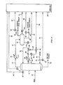
- FIGURE 2 A specific control system configuration is set forth in FIGURE 2 for the sake of illustration. However, the invention extends to different types of control system configurations which accomplish the purpose of the invention.
- Lines designated as signal lines in the drawings are electrical or pneumatic in this preferred embodiment.
- the signals provided from any transducer are electrical in form.
- the signals provided from flow sensors will generally be pneumatic in form. Transducing of these signals is not illustrated for the sake of simplicity because it is well known in the art that if a flow is measured in pneumatic form it must be transduced to electrical form if it is to be transmitted in electrical form by a flow transducer.
- transducing of the signals from analog form to digital form or from digital form to analog form is not illustrated because such transducing is also well known in the art.
- the invention is also applicable to mechanical, hydraulic or other signal means for transmitting information. In almost all control systems some combination of electrical, pneumatic, mechanical or hydraulic signals will be used. However, use of any other type of signal transmission, compatible with the process and equipment in use, is within the scope of the invention.
- a digital computer is used in the preferred embodiment of this invention to calculate the required control signals based on measured process parameters as well as set points supplied to the computer. Analog computers or other types of computing devices could also be used in the invention.
- the digital computer is preferably an OPTROL 7000 Process Computer System from Applied Automation, Inc., Bartlesville, Oklahoma.
- Signal lines are also utilized to represent the results of calculations carried out in a digital computer and the term "signal" is utilized to refer to such results.
- signal is used not only to refer to electrical currents or pneumatic pressures but is also used to refer to binary representations of a calculated or measured value.
- controllers shown may utilize the various modes of control such as proportional, proportional-integral, proportional-derivative, or proportional-integral-derivative.
- proportional-integral-derivative controllers are utilized but any controller capable of accepting two input signals and producing a scaled output signal, representative of a comparison of the two input signals, is within the scope of the invention.
- the scaling of an output signal by a controller is well known in the control system art. Essentially, the output of a controller may be scaled to represent any desired factor or variable. An example of this is where a desired flow rate and an actual flow rate is compared by a controller. The output could be a signal representative of a desired change in the flow rate of some gas necessary to make the desired and actual flows equal. On the other hand, the same output signal could be scaled to represent a percentage or could be scaled to represent a temperature change required to make the desired and actual flows equal. If the controller output can range from 0 to 10 volts, which is typical, then the output signal could be scaled so that an output signal having a voltage level of 5.0 volts corresponds to 50 percent, some specified flow rate, or some specified temperature.
- the various transducing means used to measure parameters which characterize the process and the various signals generated thereby may take a variety of forms or formats.
- the control elements of the system can be implemented using electrical analog, digital electronic, pneumatic, hydraulic, mechanical or other similar types of equipment or combination of one or more such equipment types. While the presently preferred embodiment of the invention preferably utilizes a combination of pneumatic final control elements in conjunction with electrical analog signal handling and translation apparatus, the apparatus and method of the invention can be implemented using a variety of specific equipment available to and understood by those skilled in the process control art.
- the format of the various signals can be modified substantially in order to accommodate signal format requirements of the particular installation, safety factors, the physical characteristics of the measuring or control instruments and other similar factors.
- a raw flow measurement signal produced by a differential pressure orifice flow meter would ordinarily exhibit a generally proportional relationship to the square of the actual flow rate.
- Other measuring instruments might produce a signal which is proportional to the measured parameter, and still other transducing means may produce a signal which bears a more complicated, but known, relationship to the measured parameter.
- each signal representative of a measured process parameter or representative of a desired process value will bear a relationship to the measured parameter or desired value which permits designation of a specific measured or desired value by a specific signal value.
- a signal which is representative of a process measurement or desired process value is therefore one from which the information regarding the measured or desired value can be readily retrieved regardless of the exact mathematical relationship between the signal units and the measured or desired process units.
- FIGURE 2 there is illustrated a fractional distillation column 11 which is utilized to fractionate a crude oil feed into a variety of products. For the sake of simplicity, only the overhead product and bottoms product are illustrated in FIGURE 2.
- the crude oil feed is supplied to the fractional distillation column 11 through conduit means 12.
- the crude oil feed will have generally been preheated prior to entering the fractional distillation column 11.
- An overhead stream is provided from the fractional distillation column 11 through conduit means 15 to the heat exchanger 16.
- the heat exchanger 16 is provided with a cooling medium flowing through conduit means 17.
- a fluid stream from the heat exchanger 16 is provided to the overhead accumulator 18 through conduit means 21.
- Vapor in the overhead accumulator 18 is withdrawn from the overhead accumulator through conduit means 22 and is generally referred to as the overhead vapor product.
- Liquid in the overhead accumulator 18 is withdrawn from the overhead accumulator through conduit means 23 and is generally referred to as the overhead liquid product.
- the fluid stream flowing through conduit means 31 is provided to the heat exchanger 32.
- the heat exchanger 32 is also provided with a cooling medium flowing through conduit means 34.
- the fluid stream from the heat exchanger 32 is provided to the top of the fractional distillation column 11 through conduit means 36.
- a bottoms stream generally containing reduced crude oil is withdrawn from the fractional distillation column 11 through conduit means 38.
- Steam is provided to the fractional distillation column 11 through conduit means 39. It is noted that, in many cases, heat would be provided to the fractional.distillation column by a fired reboiler or by circulating steam through conduits in the fractional distillation column. However, again, on the particular crude tower to which the present invention was actually applied, preheating of the feed stream was used to supply heat to the fractional distillation column and steam was used as a stripping fluid.
- the overhead liquid product is generally referred to as the naphtha product.
- a number of other side draw products such as kerosene, light cycle oil and heavy cycle oil.would generally be withdrawn from a crude tower. However, for the sake of simplicity, these remaining process streams have not been illustrated since they play no part in the invention. Also, the many pumps, additional heat exchangers, additional control components and other typical fractional distillation equipment have not been illustrated.
- temperature transducer 44 in combination with a temperature measuring device such as a thermocouple, which is operably located in the overhead accumulator 18, provides an output signal 45 which is representative of the actual temperature of the fluid in the overhead accumulator 18.
- Signal 45 is provided from temperature transducer 44 as an input to computer 100.
- Pressure transducer 47 in combination with a pressure sensing device, which is operably located in the upper portion of the fractional distillation column 11, provides an output signal 49 which is representative of the actual pressure in the upper portion of the fractional distillation column 11.
- Signal 49 is provided from the pressure transducer 47 as an input to computer 100.
- pressure transducer 50 in combination with a pressure sensing device, which is operably located in the overhead accumulator 18, provides an output signal 51 which is representative of the actual pressure in the overhead accumulator 18.
- Signal 51 is provided from the pressure transducer 50 as an input to computer 100.
- Flow transducer 52 in combination with the flow sensor 53, which is operably located in conduit means 39, provides an output signal 54 which is representative of the actual flow rate of steam through conduit means 39.
- Signal 54 is provided from the flow transducer 52 as an input to computer 100.
- flow transducer 55 in combination with flow sensor 56, which is operably located in conduit means 22, provides an output signal 57 which is representative of the actual flow rate of the overhead vapor product through conduit means 22.
- Flow transducer 58 in combination with flow sensor 59, which is operably located in conduit means 23, provides an output signal 60 which is representative of the actual flow rate of the overhead liquid product through conduit means 23. Both signals 57 and 60 are provided as inputs to computer 100.
- computer 100 calculates the flow rate of the upper external reflux required to maintain the actual ASTM end point temperature of the overhead liquid product flowing through conduit means 23 substantially equal to a desired ASTM end point temperature.
- Signal 61 which is representative of this desired flow rate, is provided from computer 100 as the set point input to the flow controller 62.
- Flow transducer 64 in combination with the flow sensor 65, which is operably located in conduit means 36, provides an output signal 66 which is representative of the actual flow rate of the upper external reflux through conduit means 36.
- Signal 66 is provided from the flow transducer 64 as the process variable input from the flow controller 62.
- the flow controller 62 In response to signals 61 and 66, the flow controller 62 provides an output signal 67 which is scaled so as to be representative of the position of the control valve 68, which is operably located in conduit means 36, required to maintain the actual flow rate of the upper external reflux through conduit means 36 substantially equal to the desired flow rate represented by signal 61.
- Signal 67 is provided from the flow controller 62 as the control signal for the control valve 68 and the control valve 68 is manipulated in response thereto.
- FIGURE 3 The logic utilized to calculate the magnitude of the set point signal 61 based on the process variables measured is illustrated in FIGURE 3.
- signal 42 which is representative of the temperature of the overhead vapor stream flowing through conduit means 15, is provided as an input to the calculate equilibrium flash vaporization end point (EFVEP) block 111.
- signal 49 which is representative of the actual pressure in the upper portion of the fractional distillation column 11, and signal 54, which is representative of the actual flow rate of steam through conduit means 39, are provided as inputs to the calculate EFVEP block 111.
- Signal 57 which is representative of the actual flow rate of the overhead vapor product, is provided as an input to the calculate EFVEP block 111 and also as an input to the calculate equilibrium flash vaporization initial point (EFVIP) block 112.
- signal 60 which is representative of the actual flow rate of the overhead liquid product is provided as an input to both the calculate EFVEP block 111 and the calculate EFVIP block 112.
- the EFVEP for the overhead liquid product is calculated in response to the described process variables as follows:
- the molecular weight of the hydrocarbons contained in the overhead liquid product may be calculated by any conventional technique.
- the molecular weight of the hydrocarbons is preferably calculated as a function of the mean average boiling point and gravity of hydrocarbons using the NGPSA Engineering Data Book published by the Natural Gas Processors Suppliers Association, 9th Edition, pages 16-25, 1972. Initial estimates of the mean average boiling point and gravity are obtained from laboratory analysis of typical products. The mean average boiling point and gravity can be periodically updated from laboratory data.
- the mean average boiling point will typically be in the range of from about 200 to about 280°F.
- the gravity will typically be in the range of about 55 to about 75° API.
- F 3 the flow rate of the steam through conduit means 39 (signal 54).
- the molecular weight of steam will be known.
- the molecular weight of the overhead product stream is calculated from laboratory data using analysis of typical samples.
- the molecular weight can be periodically updated using laboratory data.
- the molecular weight of the overhead vapor stream will typically be in the range of about 30 to about 40 pounds per mole.
- the EFVEP is equal to the boiling point of normal paraffin hydrocarbons at 760 millimeters of mercury absolute pressure.
- the EFVEP is calculated from Figure 5-27; page 208, of a book entitled Petroleum Refinery Engineering by W. L. Nelson (1958, McGraw-Hill Book Company and referred to hereianfter as "Nelson").
- Figure 5-27 the vapor pressure of Figure 5-27 is equal to the hydrocarbon partial pressure calculated in accordance with equation (1).
- the temperature required for use of Figure 5-27 to calculate the EFVEP is the temperature of the overhead vapor stream flowing through conduit means 15 (signal 42).
- the EFVEP may be determined directly from Figure 5-27 of Nelson.
- Figure 5-27 is entered into the computer by entering sets of related numbers for the partial pressure, temperature and boiling point. A regression analysis is then used to interpolate between the entered points to achieve the desired accuracy.
- Equation (3) If a steam stripping stream (or other similar stream) is not provided to the fractional distillation process, the steam term in Equation (3) will not be used. In like manner, if total condensing is used such that an overhead vapor stream is not withdrawn from the overhead accumulator, the overhead vapor term in Equation (3) will not be used.
- signal 45 which is representative of the actual temperature of the fluid in the overhead accumulator 18, is provided as an input to the EFVIP block 112.
- signal 51 which is representative of the actual pressure in the overhead accumulator 18, is provided as an input to the calculate EFVIP block 112.
- the EFVIP is calculated in exactly the same manner as previously described for the EFVEP except that the pressure used is the pressure in the overhead accumulator (signal 51) as opposed to the pressure in the upper portion of the fractional distillation column and the temperature used is the temperature of the fluid in the overhead accumulator (signal 45) as opposed to the temperature of the overhead vapor stream flowing through conduit means 15. Also, the steam flow term of Equation 3 is not used to calculate the EFVIP because all of the steam is condensed. Again, the EFVIP may be derived directly from Figure 5-27 of Nelson based on the hydrocarbon partial pressure determined (in accordance with equation (1) and the measured temperature of the fluids in the overhead accumulator 18.
- Signal 114 which is representative of the actual EFVEP of the overhead liquid product is provided from the calculate EFVEP block 111 as an input to the calculate EFV slope block 115.
- signal 117 which is representative of the actual EFVIP of the overhead liquid product, is provided from the calculate EFVIP block 112 as an input to the calculate EFV slope block 115.
- the slope calculated in accordance with equation (4) which is represented by signal 118, is provided from the calculate EFV slope block 115 as an input to the calculate ASTM slope block 119.
- An initial estimate of the slope of the ASTM boiling point curve, such as the curve illustrated in FIGURE 1, at a particular point such as the 100 percent end point, is obtained from laboratory analysis of typical samples.
- the slope of the ASTM curve will generally be in the range of about 2°F/% to about 4°F/%.
- Typical values of the slope of the EFV line are in the range of about 1°F/% to about 3°F/%.
- ASTM Slope T 1
- EFV Slope T 2
- Signal 121 which is representative of ASTM Slope (T 2 ) is provided from the calculate ASTM slope block 119 as an input to the calculate ASTM end point temperature block 123.
- the ASTM Slope (T 2 ) is utilized to derive a correction factor for the EFV end point temperature which is represented by signal 114. This is accomplished by using Figure 3.27 at page 147 of Van Winkle. Based on the ASTM Slope (T 2 ) and the end point, the correction factor can be derived directly from Figure 3.27. This correction factor is added to signal 114 to derive what will be referred to as a corrected EFV end point temperature.
- This corrected EFV end point temperature may be utilized to derive the ASTM end point temperature directly using Figure 3.26 at page 146 of Van Winkle which illustrates the relationship between the ASTM temperature and the EFV uncorrected temperature.
- Figure 3-27 of Van Winkle is entered into the computer by entering related numbers of the ASTM Slope and the Correction to EFV Temperature.
- Figure 3-26 of Van Winkle is entered into the computer by entering related numbers for ASTM Temperature and EFV Temperature. Again, a regression analysis is used to interpolate for the desired accuracy.
- Signal 125 which is representative of the actual ASTM end point temperature of the overhead liquid product is provided from the calculate ASTM end point temperature block 123 as the process variable input to the controller block 127.
- the controller block 127 is also provided with a set point signal 128 which is representative of the desired ASTM end point temperature for the overhead liquid product.
- the controller block 127 provides an output signal 61 which is scaled so as to be representative of the flow rate of the upper external reflux flowing through conduit means 36 required to maintain the actual ASTM end point temperature of the overhead liquid product substantially equal to the desired end point temperature represented by signal 128.
- Signal 61 is provided as an output from computer 100 and is utilized as is previously described.
- signal 61 is preferably scaled so as to be representative of the flow rate of the upper external reflux
- signal 61 could be scaled so as to be representative of the position of the control valve 68 required to maintain the desired ASTM end point temperature for the overhead liquid product. If this were done, there would be no need for the level of control represented by the flow controller 62 and the flow transducer 64, illustrated in FIGURE 2. However, some accuracy may be lost in directly manipulating the control valve 68 in reponse to signal 61 and it is thus preferred to utilize the level of control as described above.
- changes in the slope of the EFV boiling point line may be calculated. These changes may be utilized to update the slope of the ASTM boiling point curve periodically.
- the slope of the ASTM boiling point curve is utilized to determine the actual, current ASTM end point temperature of the overhead liquid product and this actual determination is utilized to control the fractional distillation process so as to maintain the actual ASTM end point temperature substantially equal to a desired ASTM end point temperature as set by product specifications for the overhead liquid product.
- FIGURES 1-3 The invention has been described in terms of a preferred embodiment as illustrated in FIGURES 1-3.
- Specific components used in the practice of the invention as illustrated in FIGURE 2 such as flow sensors 53, 56, 59 and 65; flow transducers 52, 55, 58 and 64; temperature transducers 41 and 44; pressure transducers 47 and 50 and control valve 68 are each well-known, commercially available control components such as are described in length in Perry's Chemical Engineers Handbook, 4th Ed., Chapter 22, McGraw-Hill.
Landscapes
- Chemical & Material Sciences (AREA)
- Chemical Kinetics & Catalysis (AREA)
- Production Of Liquid Hydrocarbon Mixture For Refining Petroleum (AREA)
- Vaporization, Distillation, Condensation, Sublimation, And Cold Traps (AREA)
- Organic Low-Molecular-Weight Compounds And Preparation Thereof (AREA)
Applications Claiming Priority (2)
| Application Number | Priority Date | Filing Date | Title |
|---|---|---|---|
| US498997 | 1983-05-27 | ||
| US06/498,997 US4558423A (en) | 1983-05-27 | 1983-05-27 | Utilization of an ASTM end point temperature for controlling a fractional distillation process |
Publications (2)
| Publication Number | Publication Date |
|---|---|
| EP0130352A2 true EP0130352A2 (de) | 1985-01-09 |
| EP0130352A3 EP0130352A3 (de) | 1986-12-30 |
Family
ID=23983366
Family Applications (1)
| Application Number | Title | Priority Date | Filing Date |
|---|---|---|---|
| EP84105968A Withdrawn EP0130352A3 (de) | 1983-05-27 | 1984-05-25 | Regelung eines Verfahrens zur fraktionierten Destillation |
Country Status (8)
| Country | Link |
|---|---|
| US (1) | US4558423A (de) |
| EP (1) | EP0130352A3 (de) |
| JP (1) | JPS59222202A (de) |
| BR (1) | BR8402075A (de) |
| CA (1) | CA1204073A (de) |
| ES (1) | ES8503962A1 (de) |
| NO (1) | NO842105L (de) |
| ZA (1) | ZA842802B (de) |
Cited By (1)
| Publication number | Priority date | Publication date | Assignee | Title |
|---|---|---|---|---|
| EP0221146A4 (de) * | 1985-05-03 | 1987-08-12 | Foxboro Co | Regelung des trennungspunktes bei der destillation. |
Families Citing this family (7)
| Publication number | Priority date | Publication date | Assignee | Title |
|---|---|---|---|---|
| US5132918A (en) * | 1990-02-28 | 1992-07-21 | Funk Gary L | Method for control of a distillation process |
| US5396416A (en) * | 1992-08-19 | 1995-03-07 | Continental Controls, Inc. | Multivariable process control method and apparatus |
| US5663492A (en) * | 1996-06-05 | 1997-09-02 | Alapati; Rama Rao | System for continuous analysis and modification of characteristics of a liquid hydrocarbon stream |
| AU783935B2 (en) * | 1999-06-18 | 2006-01-05 | Indiana University Research And Technology Corporation | Cardiomyocytes with enhanced proliferative potential, and methods for preparing and using same |
| US6869501B2 (en) | 2001-12-20 | 2005-03-22 | 3M Innovative Properties Company | Continuous process for controlled concentration of colloidal solutions |
| US20030116290A1 (en) * | 2001-12-20 | 2003-06-26 | 3M Innovative Properties Company | Continuous process for controlled evaporation of black liquor |
| WO2007033335A1 (en) * | 2005-09-14 | 2007-03-22 | Symyx Technologies, Inc. | Microscale flash separation of fluid mixtures |
Family Cites Families (9)
| Publication number | Priority date | Publication date | Assignee | Title |
|---|---|---|---|---|
| US3405035A (en) * | 1967-10-23 | 1968-10-08 | Universal Oil Prod Co | Fractionator system with side stream product removal and internal reflux control |
| US3619377A (en) * | 1969-08-04 | 1971-11-09 | Phillips Petroleum Co | Control of composition of overhead vaporous product in a partially condensing fractionation column |
| US3907388A (en) * | 1970-08-13 | 1975-09-23 | Shell Oil Co | Method for blending multiple component streams using loss-in-weight boiling point analysis |
| US3911259A (en) * | 1974-04-11 | 1975-10-07 | Texaco Inc | Means for controlling the reflux rate and the reboiler temperature of a tower |
| FR2272707B1 (fr) * | 1974-05-30 | 1977-03-11 | Elf Aquitaine | Procede de commande d'une colonne de distillation atmospherique de petrole brut |
| US3996785A (en) * | 1975-12-29 | 1976-12-14 | Texaco Inc. | Means for on-line determination of boiling point properties of crude oil |
| US4166770A (en) * | 1978-05-22 | 1979-09-04 | Phillips Petroleum Company | Fractionation control |
| US4295196A (en) * | 1980-07-02 | 1981-10-13 | Phillips Petroleum Company | Fractional distillation column control |
| US4347577A (en) * | 1980-12-15 | 1982-08-31 | Texaco Inc. | Feedstock temperature control system |
-
1983
- 1983-05-27 US US06/498,997 patent/US4558423A/en not_active Expired - Fee Related
-
1984
- 1984-04-13 ZA ZA842802A patent/ZA842802B/xx unknown
- 1984-05-02 JP JP59089191A patent/JPS59222202A/ja active Granted
- 1984-05-03 BR BR8402075A patent/BR8402075A/pt unknown
- 1984-05-16 CA CA000454505A patent/CA1204073A/en not_active Expired
- 1984-05-25 ES ES532830A patent/ES8503962A1/es not_active Expired
- 1984-05-25 EP EP84105968A patent/EP0130352A3/de not_active Withdrawn
- 1984-05-25 NO NO842105A patent/NO842105L/no unknown
Cited By (1)
| Publication number | Priority date | Publication date | Assignee | Title |
|---|---|---|---|---|
| EP0221146A4 (de) * | 1985-05-03 | 1987-08-12 | Foxboro Co | Regelung des trennungspunktes bei der destillation. |
Also Published As
| Publication number | Publication date |
|---|---|
| ES532830A0 (es) | 1985-04-01 |
| CA1204073A (en) | 1986-05-06 |
| NO842105L (no) | 1984-11-28 |
| ES8503962A1 (es) | 1985-04-01 |
| US4558423A (en) | 1985-12-10 |
| BR8402075A (pt) | 1985-03-26 |
| ZA842802B (en) | 1984-11-28 |
| JPS6320164B2 (de) | 1988-04-26 |
| EP0130352A3 (de) | 1986-12-30 |
| JPS59222202A (ja) | 1984-12-13 |
Similar Documents
| Publication | Publication Date | Title |
|---|---|---|
| US4894145A (en) | Automatic control of feedstock vacuum towers | |
| US3830698A (en) | Method and apparatus for controlling the temperature in a fractionation column | |
| EP0445966A1 (de) | Regulierung eines fraktionierten Destillationsverfahrens | |
| US3296097A (en) | Predictive control of distillation column internal reflux | |
| US4555309A (en) | Control of a fractional distillation process | |
| US4578151A (en) | Reid Vapor Pressure determination and control in fractional distillation | |
| US4558423A (en) | Utilization of an ASTM end point temperature for controlling a fractional distillation process | |
| US4371944A (en) | Ethylene process control | |
| US4166770A (en) | Fractionation control | |
| US4536606A (en) | Control of a cracking furnace | |
| EP0028023B1 (de) | Apparat und Verfahren zur Kontrolle des Temperaturprofils eines Reaktors und des Zuführungsstroms der Reaktionsteilnehmer | |
| US4367121A (en) | Fractional distillation column control | |
| US4437977A (en) | Control of a catalytic cracking unit | |
| US4371426A (en) | Control of a fractional distillation process | |
| US4667508A (en) | Reid vapor pressure determination | |
| EP0088427A1 (de) | Vorrichtung und Verfahren zum Steuern eines Alkylierungsreaktors | |
| US4560442A (en) | Fractional distillation process control | |
| US4356863A (en) | Temperature control for preheating a crude oil feedstock | |
| US4400239A (en) | Constraint control of a fractional distillation process | |
| US4434746A (en) | Control of a system for supplying heat | |
| US4318178A (en) | Control of a cracking furnace | |
| US4380317A (en) | Furnace control | |
| US4350569A (en) | Fractional distillation column control | |
| US4498916A (en) | Control of a fractional distillation process | |
| US4417311A (en) | Fractional distillation column control |
Legal Events
| Date | Code | Title | Description |
|---|---|---|---|
| PUAI | Public reference made under article 153(3) epc to a published international application that has entered the european phase |
Free format text: ORIGINAL CODE: 0009012 |
|
| AK | Designated contracting states |
Designated state(s): AT BE CH DE FR GB IT LI LU NL SE |
|
| PUAL | Search report despatched |
Free format text: ORIGINAL CODE: 0009013 |
|
| AK | Designated contracting states |
Kind code of ref document: A3 Designated state(s): AT BE CH DE FR GB IT LI LU NL SE |
|
| 17P | Request for examination filed |
Effective date: 19870601 |
|
| 17Q | First examination report despatched |
Effective date: 19881205 |
|
| RAP1 | Party data changed (applicant data changed or rights of an application transferred) |
Owner name: APPLIED AUTOMATION, INC. |
|
| STAA | Information on the status of an ep patent application or granted ep patent |
Free format text: STATUS: THE APPLICATION HAS BEEN WITHDRAWN |
|
| 18W | Application withdrawn |
Withdrawal date: 19900503 |
|
| R18W | Application withdrawn (corrected) |
Effective date: 19900503 |
|
| RIN1 | Information on inventor provided before grant (corrected) |
Inventor name: JAIN, GYAN PARKASH |