EP0130218B2 - Method of protecting file of numerical control - Google Patents
Method of protecting file of numerical control Download PDFInfo
- Publication number
- EP0130218B2 EP0130218B2 EP84900107A EP84900107A EP0130218B2 EP 0130218 B2 EP0130218 B2 EP 0130218B2 EP 84900107 A EP84900107 A EP 84900107A EP 84900107 A EP84900107 A EP 84900107A EP 0130218 B2 EP0130218 B2 EP 0130218B2
- Authority
- EP
- European Patent Office
- Prior art keywords
- file
- name
- files
- numerical control
- input means
- Prior art date
- Legal status (The legal status is an assumption and is not a legal conclusion. Google has not performed a legal analysis and makes no representation as to the accuracy of the status listed.)
- Expired - Lifetime
Links
Images

Classifications
-
- G—PHYSICS
- G06—COMPUTING OR CALCULATING; COUNTING
- G06F—ELECTRIC DIGITAL DATA PROCESSING
- G06F21/00—Security arrangements for protecting computers, components thereof, programs or data against unauthorised activity
- G06F21/60—Protecting data
- G06F21/62—Protecting access to data via a platform, e.g. using keys or access control rules
- G06F21/6209—Protecting access to data via a platform, e.g. using keys or access control rules to a single file or object, e.g. in a secure envelope, encrypted and accessed using a key, or with access control rules appended to the object itself
-
- G—PHYSICS
- G05—CONTROLLING; REGULATING
- G05B—CONTROL OR REGULATING SYSTEMS IN GENERAL; FUNCTIONAL ELEMENTS OF SUCH SYSTEMS; MONITORING OR TESTING ARRANGEMENTS FOR SUCH SYSTEMS OR ELEMENTS
- G05B19/00—Program-control systems
- G05B19/02—Program-control systems electric
- G05B19/18—Numerical control [NC], i.e. automatically operating machines, in particular machine tools, e.g. in a manufacturing environment, so as to execute positioning, movement or co-ordinated operations by means of program data in numerical form
- G05B19/408—Numerical control [NC], i.e. automatically operating machines, in particular machine tools, e.g. in a manufacturing environment, so as to execute positioning, movement or co-ordinated operations by means of program data in numerical form characterised by data handling or data format, e.g. reading, buffering or conversion of data
-
- G—PHYSICS
- G05—CONTROLLING; REGULATING
- G05B—CONTROL OR REGULATING SYSTEMS IN GENERAL; FUNCTIONAL ELEMENTS OF SUCH SYSTEMS; MONITORING OR TESTING ARRANGEMENTS FOR SUCH SYSTEMS OR ELEMENTS
- G05B2219/00—Program-control systems
- G05B2219/30—Nc systems
- G05B2219/36—Nc in input of data, input key till input tape
- G05B2219/36542—Cryptography, encrypt, access, authorize with key, code, password
Definitions
- This invention relates to a computerized numerical control unit for numerically controlling a machine tool or the like, and more particularly to a numerical control unit file protection method capable of protecting a file stored in a memory against an erroneous updating operation.
- NC units Numerical control units
- These NC units find use in applying NC techniques to a variety of machines, and the field of application thereof is ever widening.
- These NC units are now constituted by computers and are capable of implementing various functions by means of software.
- Recent NC units have a parameter control function in addition to the basic control software and are adapted so as to be able to store several files, with file names affixed thereto, in a submemory.
- diagnosis and production management are facilitated if such information as the change in status of a machine with time, as well as the operating time, is filed.
- Files of this kind are capable of being modified by deletions, substitutions and changes in file name, though the files also contain information which is desired to be left unchanged.
- NC units have become ever more simplified by adopting operator guidance and the like, and even an individual who does not possess a full understanding of NC units is capable of readily altering a file. Consequently, there are instances where important files that are not to be altered are deleted by an erroneous operation, such as by entering a file name incorrectly. Asolution to this problem is desired.
- the VAX/VMS Command Language User's Guide dated August 1978 discloses a file protection method for a data processing system having a processor, memory for storing a control program and files, and input means for accessing those files, the processor processing externally entered data in accordance with the control program.
- processing for deleting a file is executed on condition that there is a deletion confirmation input from the input means.
- a numerical control unit file protection method for a numerical control unit controlling a machine tool or the like connected thereto, the numerical control unit having a processor, a memory for storing a control program and files, and input means for accessing said files, said processor processing externally entered control data in accordance with said control program to numerically control said machine tool or the like, said method including presetting in a data memory the names of specified files which are to be protected and, when a file modification command together with the name of an object file to be modified by said command are entered from said input means, comparing the name of the object file with the preset file names, the modification command being executed if the object file name does not agree with a preset file name, whereas if the object file name does agree with one of the preset file names then the processing for modifying said object file is not executed unless there is a processing confirmation input from said input means.
- a file which is to be protected, among files which undergo modification processing is prevented from being manipulated incorrectly by an operator.
- numeral 101 denotes a paper tape bearing punched numerical control (NC) command data.
- the paper tape 101 stores NC command data such as positioning information for machining and M-, S- and T-function information.
- Numeral 102 denotes a numerical control (NC) apparatus which causes a tape reader, described below, to read in the NC data from the paper tape 101, and which decodes the read NC data, delivering, e.g., M, S and T function instructions to the machine side through a magnetics panel, not shown, when the data is indicative of such instructions, and a move command Z c to a pulse distributor, which is the succeeding stage, when the data is indicative of such a command.
- NC numerical control
- the NC apparatus 102 is composed of a processor 102a for executing processing in accordance with a control program, a program memory 102b for storing a prescribed control program, a data memory 102c for storing data, an operator's panel 102d for operator control, a tape reader/puncher 102e, a submemory 102f for storing files, an input/output port 102g, a present position counter 102h, a display unit 102i, and an address/data bus 102j interconnecting the foregoing items.
- the program memory 102b is constituted by a read-only memory (ROM) or by a non-volatile memory and stores a numerical control programe for numerically controlling a machine.
- the program memory 102b would store a machining control program for controlling machinining electrode feed, table feed and machining voltage, etc.
- the data memory 102c is composed of a non-volatile memory which, in addition to storing NC data (such as machining position data) from the paper tape 101, stores a programme machining program in an area PM in the form of parameters or user macro.
- Numeral 103 denotes a pulse distributor which executes well-known pulse distribution computations on the basis of the move command Z c , and generates distributed pulses P s at a frequency corresponding to a commanded speed.
- Numeral 104 designates a known accelerator/decelerator circuit which generates a train of pulses P ; by rectilinearly accelerating the pulse rate of the train of distributed pulses P s at the occurrence of this pulse train, and by rectilinearly decelerating the same at the end thererof.
- Numeral 105 indicates a D.C. motor by which an electrode EP is fed for machining.
- Numeral 106 denotes a pulse coder which generates one feedback pulse FP each time the DC motor rotates by a predetermined amount.
- Numeral 107 denotes an error calculating and storing unit which is constructed of, for example, a reversible counter, and which stores a difference E r between the number of the input pulses P ; generated by the accelerator/decelerator circuit 104 and that of the feedback pulses FP.
- This error calculating and storing unit may be constructed, as shown in the Figure, of an arithmetic circuit 107a for calculating the difference E r between P ; and FP, and an error register 107b for storing E r .
- the error calculating and storing unit 107 operates in such a manner that each time the input pulse P ; is generated, said pulse is counted up, while each time the feedback pulse FP is generated, the content is counted down, and that the difference E r between the number of input pulses and the number of feedback pulses is stored in the error register 107b.
- Numeral 108a denotes a digital-analog DA converter for generating an analog voltage proportional to the content of the error register 107b.
- Numeral 109 denotes a speed control circuit. It should be noted that 108, 109 construct a motor drive circuit.
- NC data is read from the paper tape 101 by the tape reader/puncher 102e, and the NC data from the paper tape 101 is stored in the data memory 102c via the bus 102j.
- a start command is applied to the processor 102a via the bus 102j by manipulating the operator's panel 102d, the processor 102a successively reads and executes the machining control program stored in the program memory 102b.
- NC parameters are read out of the data memory 102c to- getherwith the NC data
- an X-axis move command X c and Y-axis move command Yc are created for moving a table (not shown) in X and Y directions, and these commands are delivered to a table drive unit through an input/output port (not shown), whereby the table is positioned.
- an arrangement equivalent to the route extending from the input/output port 102g to the servomotor 105 is provided for each of the X and Y axes, though not shown in Fig. 1.
- the Z-axis move command Z c is created in similar fashion, and the M-, S- and T-functions are delivered to the machine side through the input/output port 102f.
- the move command Z c is delivered to the input/output port 102g via the bus 102j.
- the pulse distributor 103 produces distributed pulses P s by performing a pulse distribution operation based on the move command Z c .
- the accelerator/decelerator circuit 104 accelerates and decelerates the pulse rate thereof and applies the train of command pulses P i to the error calculating and storing circuit 107.
- the content of the error register 107b becomes non-zero, so that the DA converter 108 provides a voltage and the motor 105 is driven by the speed control unit 109 so as to move the electrode EP.
- the feedback pulse FP is generated by the pulse coder 106 and is applied to the error calculating and storing unit 107.
- the difference Er between the number of commanded pulses Pi and the number of feedback pulses FP is stored in the error register 107b.
- the motor 105 is servo-controlled so as to make the error E r approach zero, whereby the electrode EP is fed for machining and moved toward a target position.
- Items I through III are stored beforehand as files in the submemory 102 and are called to a screen for reference when data are entered. Items IV, V are created as the machine is operated and are called to the screen for confirmation when necessary.
- the files are stored in the submemory 102f upon being provided with file names, and the files are accessed by entering the filenames. Among the files there are those that are to be left unchanged. Such files require protection.
- files F1, F2, F3 ... that are stored in the submemory 102f are preset as system parameter data in the parameter area PM of the data memory 102c.
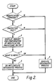
- Fig. 2 is a flowchart of processing embodying the present invention.
- an operation command and the name of the object file are entered from the operator's panel 102d. These are transmitted to the processor 102a via the bus 102j.
- the processor 102a is placed under the control of a file processing program in the program memory 102b and determines whether the operation command is one of the aforementioned modification commands (a), (b), (c). If the command is not a modification command, the processing designated is executed.
- the command is a modification command
- the file name entered is compared with protected file names f1, f2 stored in the parameter area PM of the data memory 102, whereby it is determined whether the file is a protected file. If it is not, the designated modification process is executed.
- the processor 102a causes the display device 102i to display an inquiry via the bus 102j. Specifically, the display device 102i will present a display reading "OKTO MODIFY ENTERED FILE?".
- the op- erator verifies the entered file name, checks to determine whether there is an error, and enters "NO" from the operator's panel 102d, whereby the processor 102a ends processing without executing the designated modification process.
- "OK" is entered from the operator's panel 102d, upon which the processor 102a executes the modification process for the file in the submemory 102f corresponding to the entered file name.
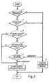
- Fig. 3 is a flowchart of processing according to another embodiment of the present invention. This embodiment differs from that of Fig. 2 in that confirmation of the modification process is performed by keyword entry and collation rather than by an inquiry. That is, entry of a keyword from the operator's panel 102d is set as a condition in addition to entry of the operation command and object file name. After steps (2), (3) identical to those in Fig. 2 are executed, (7) the processor 102a determines whether a keyword is registered in the parameter area PM of the data memory 102c. If no keyword is registered, processing ends without execution of the designated process. (8) If a keyword is registered, on the other hand, the processor 102a determines whether a keyword has been entered from the operator's panel 102d.
- the processor 102a compares the entered keyboard with the keyword stored in the parameter area PM of the data memory 102c. The processor ends processing without executing the designated process if the two keyboards fail to agree, and executes the designated modification process when the key-words do agree.
- the foregoing relates to a case where the invention is applied to a die-milling electric discharge machine.
- the present invention can also be applied to an NC automatic programming apparatus or the like, in which case the files would be (i) material files specifying cutting conditions conforming to various workpiece materials (iron, aluminum, stainless steel ...), and (ii) files used to enter quadrants drawn on a design drawing.
- a numerical control unit having a processor, a memory and input means, files and the name of a file to be protected are stored in the memory, a comparison is made with the name of the protected file in the memory in accordance with a modification command and a file name entered from the input means, and file modifiation processing is permitted when the entered file name is the protected file and, further, on the condition that there is a processing confirmation input from the input means. Accordingly, the embodiments prevent modification of a protected file in response to erroneous entry of a file name or an erroneous operation command input from the input means.
- a protected file can be modified with ease upon entry of a processing confirmation input, and modification of an unprotected file can be performed exactly as in the prior art.
- a request for a prescribed confirmatory operation is made with respect to a protected file, thus to protect against an erroneous operation by the operator.
- the present embodiments therefore have important practical advantages.
- a file which is to be protected among files which undergo modification processing, is prevented from being manipulated incorrectly by an operator. Accordingly, the present invention may be applied to protection of data in a computerized numerical control unit.
Landscapes
- Engineering & Computer Science (AREA)
- General Physics & Mathematics (AREA)
- Theoretical Computer Science (AREA)
- Physics & Mathematics (AREA)
- General Health & Medical Sciences (AREA)
- Automation & Control Theory (AREA)
- Health & Medical Sciences (AREA)
- Bioethics (AREA)
- Manufacturing & Machinery (AREA)
- Computer Hardware Design (AREA)
- Computer Security & Cryptography (AREA)
- Software Systems (AREA)
- General Engineering & Computer Science (AREA)
- Human Computer Interaction (AREA)
- Numerical Control (AREA)
- Storage Device Security (AREA)
- Safety Devices In Control Systems (AREA)
Abstract
Description
- This invention relates to a computerized numerical control unit for numerically controlling a machine tool or the like, and more particularly to a numerical control unit file protection method capable of protecting a file stored in a memory against an erroneous updating operation.
- Numerical control units (hereafter referred to as "NC units") find use in applying NC techniques to a variety of machines, and the field of application thereof is ever widening. These NC units are now constituted by computers and are capable of implementing various functions by means of software. Recent NC units have a parameter control function in addition to the basic control software and are adapted so as to be able to store several files, with file names affixed thereto, in a submemory. By way of example, diagnosis and production management are facilitated if such information as the change in status of a machine with time, as well as the operating time, is filed. Files of this kind are capable of being modified by deletions, substitutions and changes in file name, though the files also contain information which is desired to be left unchanged.
- The operation of NC units has become ever more simplified by adopting operator guidance and the like, and even an individual who does not possess a full understanding of NC units is capable of readily altering a file. Consequently, there are instances where important files that are not to be altered are deleted by an erroneous operation, such as by entering a file name incorrectly. Asolution to this problem is desired.
- The Radio Shack TRS-80 Model II Operation Manual published in 1979 addresses the problem of protecting files against deletion in a PC. However, there is a no list of protected files and the deletion of individual named files is not protected against erroneous operation.
- The VAX/VMS Command Language User's Guide dated August 1978 discloses a file protection method for a data processing system having a processor, memory for storing a control program and files, and input means for accessing those files, the processor processing externally entered data in accordance with the control program. When a deletion command is entered from the input means, processing for deleting a file is executed on condition that there is a deletion confirmation input from the input means.
- According to the present invention there is provided a numerical control unit file protection method for a numerical control unit controlling a machine tool or the like connected thereto, the numerical control unit having a processor, a memory for storing a control program and files, and input means for accessing said files, said processor processing externally entered control data in accordance with said control program to numerically control said machine tool or the like, said method including presetting in a data memory the names of specified files which are to be protected and, when a file modification command together with the name of an object file to be modified by said command are entered from said input means, comparing the name of the object file with the preset file names, the modification command being executed if the object file name does not agree with a preset file name, whereas if the object file name does agree with one of the preset file names then the processing for modifying said object file is not executed unless there is a processing confirmation input from said input means. According to the present invention, a file which is to be protected, among files which undergo modification processing, is prevented from being manipulated incorrectly by an operator.
-
- Fig. 1 is a block diagram illustrating an embodiment utilising the present invention, Fig. 2 is a flowchart of processing embodying the present invention, and Fig. 3 is a flowchart of processing according to another version of the present invention.
- Fig. 1 is a block diagram illustrating an embodiment utilising the present invention and shows a numerical control unit applied to a die-milling electric discharge machine.
- In the Figure,
numeral 101 denotes a paper tape bearing punched numerical control (NC) command data. Specifically, thepaper tape 101 stores NC command data such as positioning information for machining and M-, S- and T-function information. Numeral 102 denotes a numerical control (NC) apparatus which causes a tape reader, described below, to read in the NC data from thepaper tape 101, and which decodes the read NC data, delivering, e.g., M, S and T function instructions to the machine side through a magnetics panel, not shown, when the data is indicative of such instructions, and a move command Zc to a pulse distributor, which is the succeeding stage, when the data is indicative of such a command. TheNC apparatus 102 is composed of a processor 102a for executing processing in accordance with a control program, aprogram memory 102b for storing a prescribed control program, adata memory 102c for storing data, an operator'spanel 102d for operator control, a tape reader/puncher 102e, a submemory 102f for storing files, an input/output port 102g, apresent position counter 102h, adisplay unit 102i, and an address/data bus 102j interconnecting the foregoing items. - The
program memory 102b is constituted by a read-only memory (ROM) or by a non-volatile memory and stores a numerical control programe for numerically controlling a machine. By way of example, for an electric discharge machine, theprogram memory 102b would store a machining control program for controlling machinining electrode feed, table feed and machining voltage, etc. Thedata memory 102c is composed of a non-volatile memory which, in addition to storing NC data (such as machining position data) from thepaper tape 101, stores a programme machining program in an area PM in the form of parameters or user macro. - Numeral 103 denotes a pulse distributor which executes well-known pulse distribution computations on the basis of the move command Zc, and generates distributed pulses Ps at a frequency corresponding to a commanded speed. Numeral 104 designates a known accelerator/decelerator circuit which generates a train of pulses P; by rectilinearly accelerating the pulse rate of the train of distributed pulses Ps at the occurrence of this pulse train, and by rectilinearly decelerating the same at the end thererof.
Numeral 105 indicates a D.C. motor by which an electrode EP is fed for machining. Numeral 106 denotes a pulse coder which generates one feedback pulse FP each time the DC motor rotates by a predetermined amount. Numeral 107 denotes an error calculating and storing unit which is constructed of, for example, a reversible counter, and which stores a difference Er between the number of the input pulses P; generated by the accelerator/decelerator circuit 104 and that of the feedback pulses FP. This error calculating and storing unit may be constructed, as shown in the Figure, of anarithmetic circuit 107a for calculating the difference Er between P; and FP, and anerror register 107b for storing Er. More specifically, assuming that theDC motor 105 is rotating in the forward direction in accordance with a command causing theDC motor 105 to rotate in this direction, the error calculating and storingunit 107 operates in such a manner that each time the input pulse P; is generated, said pulse is counted up, while each time the feedback pulse FP is generated, the content is counted down, and that the difference Er between the number of input pulses and the number of feedback pulses is stored in theerror register 107b. Numeral 108a denotes a digital-analog DA converter for generating an analog voltage proportional to the content of theerror register 107b.Numeral 109 denotes a speed control circuit. It should be noted that 108, 109 construct a motor drive circuit. - The operation of the arrangement embodied in Fig. 1 will now be described.
- First, prior to machining, NC data is read from the
paper tape 101 by the tape reader/puncher 102e, and the NC data from thepaper tape 101 is stored in thedata memory 102c via thebus 102j. Next, when a start command is applied to the processor 102a via thebus 102j by manipulating the operator'spanel 102d, the processor 102a successively reads and executes the machining control program stored in theprogram memory 102b. Specificaly, required parameters (NC parameters, feed speed, machining voltage, etc.) are read out of thedata memory 102c to- getherwith the NC data, an X-axis move command Xc and Y-axis move command Yc are created for moving a table (not shown) in X and Y directions, and these commands are delivered to a table drive unit through an input/output port (not shown), whereby the table is positioned. It should be noted that an arrangement equivalent to the route extending from the input/output port 102g to theservomotor 105 is provided for each of the X and Y axes, though not shown in Fig. 1. The Z-axis move command Zc is created in similar fashion, and the M-, S- and T-functions are delivered to the machine side through the input/output port 102f. The move command Zc is delivered to the input/output port 102g via thebus 102j. When the move command is applied to thepulse distributor 103 from the input/output port 102g, thepulse distributor 103 produces distributed pulses Ps by performing a pulse distribution operation based on the move command Zc. Upon receiving the pulses Ps, the accelerator/decelerator circuit 104 accelerates and decelerates the pulse rate thereof and applies the train of command pulses Pi to the error calculating and storingcircuit 107. Thus, the content of theerror register 107b becomes non-zero, so that theDA converter 108 provides a voltage and themotor 105 is driven by thespeed control unit 109 so as to move the electrode EP. When themotor 105 has rotated by a predetermined amount, the feedback pulse FP is generated by thepulse coder 106 and is applied to the error calculating and storingunit 107. The difference Er between the number of commanded pulses Pi and the number of feedback pulses FP is stored in theerror register 107b. Thenceforth, themotor 105 is servo-controlled so as to make the error Er approach zero, whereby the electrode EP is fed for machining and moved toward a target position. - Avariety of files, of which the following are examples, are registered in the submemory 102:
- I. Feed velocity conforming to workpiece material
- II. Applied current conforming to workpiece material
- III. Override quantity conforming to workpiece material
- IV. Machine status information
- V. Operating time for each process
- Items I through III are stored beforehand as files in the
submemory 102 and are called to a screen for reference when data are entered. Items IV, V are created as the machine is operated and are called to the screen for confirmation when necessary. - The files are stored in the submemory 102f upon being provided with file names, and the files are accessed by entering the filenames. Among the files there are those that are to be left unchanged. Such files require protection.
- To this end, according to the present invention, among the files F1, F2, F3 ... that are stored in the submemory 102f, files f1, f2 that are to be protected are preset as system parameter data in the parameter area PM of the
data memory 102c. - When the next operation is carried out, it is confirmed whether there is protected file stored in the parameter area PM, followed by executing the following operations:
- (a) file deletion
- (b) file substitution
- (c) file name change
- Fig. 2 is a flowchart of processing embodying the present invention. (1) To access a file in the submemory 102f, an operation command and the name of the object file are entered from the operator's
panel 102d. These are transmitted to the processor 102a via the bus 102j. (2) As a result, the processor 102a is placed under the control of a file processing program in theprogram memory 102b and determines whether the operation command is one of the aforementioned modification commands (a), (b), (c). If the command is not a modification command, the processing designated is executed. (3) If the command is a modification command, then the file name entered is compared with protected file names f1, f2 stored in the parameter area PM of thedata memory 102, whereby it is determined whether the file is a protected file. If it is not, the designated modification process is executed. (4) If the file is a protected file, then the processor 102a causes thedisplay device 102i to display an inquiry via thebus 102j. Specifically, thedisplay device 102i will present a display reading "OKTO MODIFY ENTERED FILE?". (5) In response, the op- eratorverifies the entered file name, checks to determine whether there is an error, and enters "NO" from the operator'spanel 102d, whereby the processor 102a ends processing without executing the designated modification process. (6) If there is no error, on the other hand, then "OK" is entered from the operator'spanel 102d, upon which the processor 102a executes the modification process for the file in the submemory 102f corresponding to the entered file name. - Fig. 3 is a flowchart of processing according to another embodiment of the present invention. This embodiment differs from that of Fig. 2 in that confirmation of the modification process is performed by keyword entry and collation rather than by an inquiry. That is, entry of a keyword from the operator's
panel 102d is set as a condition in addition to entry of the operation command and object file name. After steps (2), (3) identical to those in Fig. 2 are executed, (7) the processor 102a determines whether a keyword is registered in the parameter area PM of thedata memory 102c. If no keyword is registered, processing ends without execution of the designated process. (8) If a keyword is registered, on the other hand, the processor 102a determines whether a keyword has been entered from the operator'spanel 102d. If no keyword has been entered, processing ends without execution of the designated process. (9) If a keyword has been entered, on the other hand, the processor 102a compares the entered keyboard with the keyword stored in the parameter area PM of thedata memory 102c. The processor ends processing without executing the designated process if the two keyboards fail to agree, and executes the designated modification process when the key-words do agree. - The foregoing relates to a case where the invention is applied to a die-milling electric discharge machine. However, the present invention can also be applied to an NC automatic programming apparatus or the like, in which case the files would be (i) material files specifying cutting conditions conforming to various workpiece materials (iron, aluminum, stainless steel ...), and (ii) files used to enter quadrants drawn on a design drawing.
- According to the embodiments as described above, in a numerical control unit having a processor, a memory and input means, files and the name of a file to be protected are stored in the memory, a comparison is made with the name of the protected file in the memory in accordance with a modification command and a file name entered from the input means, and file modifiation processing is permitted when the entered file name is the protected file and, further, on the condition that there is a processing confirmation input from the input means. Accordingly, the embodiments prevent modification of a protected file in response to erroneous entry of a file name or an erroneous operation command input from the input means. In addition, a protected file can be modified with ease upon entry of a processing confirmation input, and modification of an unprotected file can be performed exactly as in the prior art. In other words, among files which are to undergo modification processing, a request for a prescribed confirmatory operation is made with respect to a protected file, thus to protect against an erroneous operation by the operator. The present embodiments therefore have important practical advantages.
- It should be noted that while the present invention has been described in accordance with embodiments thereof, the present invention is not limited to the above-described embodiments but can be modified in various ways in accordance with the gist thereof, and that such modifications will not depart from the scope of the claim.
- According to the present invention, a file which is to be protected, among files which undergo modification processing, is prevented from being manipulated incorrectly by an operator. Accordingly, the present invention may be applied to protection of data in a computerized numerical control unit.
Claims (3)
Applications Claiming Priority (3)
| Application Number | Priority Date | Filing Date | Title |
|---|---|---|---|
| JP228510/82 | 1982-12-29 | ||
| JP57228510A JPS59123002A (en) | 1982-12-29 | 1982-12-29 | File protecting system for numerical controller |
| PCT/JP1983/000440 WO1984002589A1 (en) | 1982-12-29 | 1983-12-16 | Method of protecting file of numerical control |
Publications (4)
| Publication Number | Publication Date |
|---|---|
| EP0130218A1 EP0130218A1 (en) | 1985-01-09 |
| EP0130218A4 EP0130218A4 (en) | 1987-02-26 |
| EP0130218B1 EP0130218B1 (en) | 1990-03-21 |
| EP0130218B2 true EP0130218B2 (en) | 1994-12-14 |
Family
ID=16877558
Family Applications (1)
| Application Number | Title | Priority Date | Filing Date |
|---|---|---|---|
| EP84900107A Expired - Lifetime EP0130218B2 (en) | 1982-12-29 | 1983-12-16 | Method of protecting file of numerical control |
Country Status (5)
| Country | Link |
|---|---|
| US (1) | US4884211A (en) |
| EP (1) | EP0130218B2 (en) |
| JP (1) | JPS59123002A (en) |
| DE (1) | DE3381360D1 (en) |
| WO (1) | WO1984002589A1 (en) |
Families Citing this family (10)
| Publication number | Priority date | Publication date | Assignee | Title |
|---|---|---|---|---|
| JPS621003A (en) * | 1985-06-26 | 1987-01-07 | Amada Co Ltd | Numerical controller capable of changing setting of memory contents |
| JPS62100805A (en) * | 1985-10-28 | 1987-05-11 | Omron Tateisi Electronics Co | Programmable controller |
| US4930073A (en) * | 1987-06-26 | 1990-05-29 | International Business Machines Corporation | Method to prevent use of incorrect program version in a computer system |
| FR2623640B1 (en) * | 1987-11-19 | 1990-03-16 | Dassault Electronique | MICRO-COMPUTING DEVICE AGAINST THE CONDUCT OF FRAUDULENT PROGRAMS |
| JPH0820944B2 (en) * | 1989-03-20 | 1996-03-04 | 株式会社日立製作所 | Computerized information creation device |
| KR930002655Y1 (en) * | 1990-12-28 | 1993-05-19 | 삼성전자 주식회사 | User program back-up device with erasable programmable read only memory |
| US5537029A (en) | 1992-02-21 | 1996-07-16 | Abb Power T&D Company Inc. | Method and apparatus for electronic meter testing |
| US6324537B1 (en) * | 1999-09-30 | 2001-11-27 | M-Systems Flash Disk Pioneers Ltd. | Device, system and method for data access control |
| US6971018B1 (en) * | 2000-04-28 | 2005-11-29 | Microsoft Corporation | File protection service for a computer system |
| IL148834A (en) | 2000-09-10 | 2007-03-08 | Sandisk Il Ltd | Removable, active, personal storage device, system and method |
Family Cites Families (19)
| Publication number | Priority date | Publication date | Assignee | Title |
|---|---|---|---|---|
| US3576544A (en) * | 1968-10-18 | 1971-04-27 | Ibm | Storage protection system |
| US3599159A (en) * | 1970-04-09 | 1971-08-10 | Bobby A Creech | Digital memory with automatic overwrite protection |
| JPS4930578B1 (en) * | 1970-09-30 | 1974-08-14 | ||
| US3744034A (en) * | 1972-01-27 | 1973-07-03 | Perkin Elmer Corp | Method and apparatus for providing a security system for a computer |
| US3893084A (en) * | 1973-05-01 | 1975-07-01 | Digital Equipment Corp | Memory access control system |
| US4135240A (en) * | 1973-07-09 | 1979-01-16 | Bell Telephone Laboratories, Incorporated | Protection of data file contents |
| US3890601A (en) * | 1974-03-11 | 1975-06-17 | Philco Ford Corp | Password operated system for preventing unauthorized or accidental computer memory alteration |
| US4104718A (en) * | 1974-12-16 | 1978-08-01 | Compagnie Honeywell Bull (Societe Anonyme) | System for protecting shared files in a multiprogrammed computer |
| US4118789A (en) * | 1977-06-06 | 1978-10-03 | Allen-Bradley Company | Program protection module for programmable controller |
| JPS5437650A (en) * | 1977-08-31 | 1979-03-20 | Toshiba Corp | Information processing system |
| JPS5441629A (en) * | 1977-09-09 | 1979-04-03 | Casio Comput Co Ltd | Output control system of program information |
| DE2838063A1 (en) * | 1978-08-31 | 1980-03-13 | Siemens Ag | TEXT EDITING DEVICE |
| JPS5580165A (en) * | 1978-12-12 | 1980-06-17 | Fujitsu Ltd | File processing system |
| JPS5672772A (en) * | 1979-11-19 | 1981-06-17 | Toshiba Corp | Storage retrieval system for picture information |
| US4332009A (en) * | 1980-01-21 | 1982-05-25 | Mostek Corporation | Memory protection system |
| JPS5758292A (en) * | 1980-09-25 | 1982-04-07 | Fanuc Ltd | File deleting method for bubble cassette memory |
| JPS57206977A (en) * | 1981-06-15 | 1982-12-18 | Fujitsu Ltd | Document processing system |
| US4471163A (en) * | 1981-10-05 | 1984-09-11 | Donald Thomas C | Software protection system |
| US4458315A (en) * | 1982-02-25 | 1984-07-03 | Penta, Inc. | Apparatus and method for preventing unauthorized use of computer programs |
-
1982
- 1982-12-29 JP JP57228510A patent/JPS59123002A/en active Pending
-
1983
- 1983-12-16 DE DE8484900107T patent/DE3381360D1/en not_active Expired - Lifetime
- 1983-12-16 WO PCT/JP1983/000440 patent/WO1984002589A1/en not_active Ceased
- 1983-12-16 EP EP84900107A patent/EP0130218B2/en not_active Expired - Lifetime
-
1988
- 1988-05-18 US US07/196,783 patent/US4884211A/en not_active Expired - Fee Related
Also Published As
| Publication number | Publication date |
|---|---|
| EP0130218A4 (en) | 1987-02-26 |
| JPS59123002A (en) | 1984-07-16 |
| EP0130218A1 (en) | 1985-01-09 |
| US4884211A (en) | 1989-11-28 |
| DE3381360D1 (en) | 1990-04-26 |
| EP0130218B1 (en) | 1990-03-21 |
| WO1984002589A1 (en) | 1984-07-05 |
Similar Documents
| Publication | Publication Date | Title |
|---|---|---|
| US4513379A (en) | Customization window for a computer numerical control system | |
| EP0130218B2 (en) | Method of protecting file of numerical control | |
| EP2104013B1 (en) | Numerical controller with machining restart function | |
| US20230286169A1 (en) | Numerical control system and robot control method | |
| JP2757590B2 (en) | Numerical control unit | |
| EP0120975B1 (en) | Numerical controlling device and method | |
| EP0270678B1 (en) | Apparatus for processing numerical control program | |
| JPS6267607A (en) | Automatic programming device | |
| US5060163A (en) | Programming apparatus for lathes | |
| KR970009980A (en) | Work area control method of machine tool | |
| CN116057482B (en) | Controls | |
| JP4151402B2 (en) | Numerical controller with parameter rewriting history function | |
| JPH0563749U (en) | Numerical control device with processing time calculation function | |
| JP3092744B2 (en) | Processing system | |
| JP7827878B2 (en) | Machine tool control device and machine tool display device | |
| EP0160099A1 (en) | Method of retrieving coded instructions for a machining system | |
| JP2670180B2 (en) | Numerical control information creation device | |
| JPH05143130A (en) | Numerical controller | |
| HK40089301A (en) | Method for the preparation of urea compounds as smarca2/brm-atpase inhibitors | |
| JPH11165238A (en) | Feed rate control method and apparatus in numerical control | |
| Furth | Plant automation | |
| JP2788557B2 (en) | Numerical control unit | |
| JPS59205253A (en) | Tool interference checking method for tetraxial lathe | |
| JPH07237086A (en) | Preparating method for program used for numerically controlled machine tool | |
| JPH07108437A (en) | Data control method for machining |
Legal Events
| Date | Code | Title | Description |
|---|---|---|---|
| PUAI | Public reference made under article 153(3) epc to a published international application that has entered the european phase |
Free format text: ORIGINAL CODE: 0009012 |
|
| 17P | Request for examination filed |
Effective date: 19840830 |
|
| AK | Designated contracting states |
Designated state(s): DE FR GB |
|
| A4 | Supplementary search report drawn up and despatched |
Effective date: 19870226 |
|
| 17Q | First examination report despatched |
Effective date: 19880906 |
|
| GRAA | (expected) grant |
Free format text: ORIGINAL CODE: 0009210 |
|
| AK | Designated contracting states |
Kind code of ref document: B1 Designated state(s): DE FR GB |
|
| REF | Corresponds to: |
Ref document number: 3381360 Country of ref document: DE Date of ref document: 19900426 |
|
| ET | Fr: translation filed | ||
| PGFP | Annual fee paid to national office [announced via postgrant information from national office to epo] |
Ref country code: FR Payment date: 19901129 Year of fee payment: 8 |
|
| PGFP | Annual fee paid to national office [announced via postgrant information from national office to epo] |
Ref country code: GB Payment date: 19901204 Year of fee payment: 8 |
|
| PLBI | Opposition filed |
Free format text: ORIGINAL CODE: 0009260 |
|
| 26 | Opposition filed |
Opponent name: ROBERT BOSCH GMBH Effective date: 19901221 |
|
| PG25 | Lapsed in a contracting state [announced via postgrant information from national office to epo] |
Ref country code: GB Effective date: 19911216 |
|
| GBPC | Gb: european patent ceased through non-payment of renewal fee | ||
| PG25 | Lapsed in a contracting state [announced via postgrant information from national office to epo] |
Ref country code: FR Effective date: 19920831 |
|
| REG | Reference to a national code |
Ref country code: FR Ref legal event code: ST |
|
| PUAH | Patent maintained in amended form |
Free format text: ORIGINAL CODE: 0009272 |
|
| STAA | Information on the status of an ep patent application or granted ep patent |
Free format text: STATUS: PATENT MAINTAINED AS AMENDED |
|
| 27A | Patent maintained in amended form |
Effective date: 19941214 |
|
| AK | Designated contracting states |
Kind code of ref document: B2 Designated state(s): DE FR GB |
|
| EN3 | Fr: translation not filed ** decision concerning opposition | ||
| PGFP | Annual fee paid to national office [announced via postgrant information from national office to epo] |
Ref country code: DE Payment date: 19951214 Year of fee payment: 13 |
|
| PG25 | Lapsed in a contracting state [announced via postgrant information from national office to epo] |
Ref country code: DE Effective date: 19970902 |