EP0130168B1 - Pneumatic rotary grinding tool - Google Patents
Pneumatic rotary grinding tool Download PDFInfo
- Publication number
- EP0130168B1 EP0130168B1 EP84850206A EP84850206A EP0130168B1 EP 0130168 B1 EP0130168 B1 EP 0130168B1 EP 84850206 A EP84850206 A EP 84850206A EP 84850206 A EP84850206 A EP 84850206A EP 0130168 B1 EP0130168 B1 EP 0130168B1
- Authority
- EP
- European Patent Office
- Prior art keywords
- motor unit
- housing
- grinding tool
- safety guard
- operative position
- Prior art date
- Legal status (The legal status is an assumption and is not a legal conclusion. Google has not performed a legal analysis and makes no representation as to the accuracy of the status listed.)
- Expired
Links
- 230000001681 protective effect Effects 0.000 claims description 3
- 231100001261 hazardous Toxicity 0.000 description 2
- 230000004913 activation Effects 0.000 description 1
- 238000006073 displacement reaction Methods 0.000 description 1
- 230000005484 gravity Effects 0.000 description 1
- 239000002245 particle Substances 0.000 description 1
- 230000000284 resting effect Effects 0.000 description 1
Images
Classifications
-
- B—PERFORMING OPERATIONS; TRANSPORTING
- B24—GRINDING; POLISHING
- B24B—MACHINES, DEVICES, OR PROCESSES FOR GRINDING OR POLISHING; DRESSING OR CONDITIONING OF ABRADING SURFACES; FEEDING OF GRINDING, POLISHING, OR LAPPING AGENTS
- B24B55/00—Safety devices for grinding or polishing machines; Accessories fitted to grinding or polishing machines for keeping tools or parts of the machine in good working condition
- B24B55/04—Protective covers for the grinding wheel
- B24B55/05—Protective covers for the grinding wheel specially designed for portable grinding machines
- B24B55/052—Protective covers for the grinding wheel specially designed for portable grinding machines with rotating tools
-
- B—PERFORMING OPERATIONS; TRANSPORTING
- B24—GRINDING; POLISHING
- B24B—MACHINES, DEVICES, OR PROCESSES FOR GRINDING OR POLISHING; DRESSING OR CONDITIONING OF ABRADING SURFACES; FEEDING OF GRINDING, POLISHING, OR LAPPING AGENTS
- B24B23/00—Portable grinding machines, e.g. hand-guided; Accessories therefor
- B24B23/02—Portable grinding machines, e.g. hand-guided; Accessories therefor with rotating grinding tools; Accessories therefor
- B24B23/026—Fluid driven
Definitions
- the invention intends to solve the problem of how to prevent use of a grinding tool of the above type when the safety guard is not properly fitted.
- Using the tool without having the safety guard fitted means an increased risk of injure for the operator and other people in the vicinity of the tool, because there is always a potential danger involved in the use of a rotary grinding tool.
- a grinding wheel exposed to excessive inertia forces at overspeed conditions might suddenly burst into a number of most dangerous high speed particles.
- a safety guard 18 is rigidly attached to the housing 10 by means of screws 19.
- the safety guard 18 is mounted in a protective disposition relative to the grinding wheel 17 which means that the safety guard 18 partly surrounds the latter.
- the motor unit 15 comprises a speed control means (not shown in detail) coupled to the motor 21 and enclosed in a cup-shaped shell 22.
- the speed control means comprises a speed governor and in some cases also an overspeed responsive shutoff valve. Since the speed control means does not form any part of this invention we prefer not to make the specification too long by incorporating a detailed description thereof.
- the housing 10 incorporates an air supply passage 12 which extends into the rear part of housing 10.
- the motor unit 15 comprises an air inlet port 33 and air outlet ports 34.
- In the front part of the housing 10 there is an exhaust passage 35 which via openings 36 communicates with the atmosphere.
- the exhaust passage 35 is formed by an annular space left between the motor unit 15 and the housing 10.
- the motor unit 15 is formed with a small diameter extension 37 which cooperates with an aperture 38 in the housing 10.
- the aperture 38 is of circular cross section whereas the motor unit extension 37 is formed with a number of axially directed flats or grooves 39.
- the extension 37 carries a circular seal ring 40 which is arranged to sealingly cooperate with the wall of the aperture 38 as the motor unit 15 occupies its rear operative position in the housing 10.
- the safety guard 18, when properly mounted on the housing 10 by means of the screws 19 transfers an axial clamping force to the support sleeve 30.
- the seal ring 40 on the rear motor unit extension 37 cooperates with the aperture 38 in the housing 10 and seals off the housing 10 from the atmosphere.
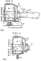
- the operation conditions of the tool is quite different when no safety guard is fitted. Since there is no axial support for the distance sleeve 30 there is no clamping force to keep the motor unit 15 in the rear operative position and to maintain the seal ring 25 in active position between the opposite shoulders 23, 24. This means that if and when pressure air is supplied through passage 12 the motor unit will be dislocated forwards by the air pressure, and may be also by gravity, and will occupy the position shown in Fig. 2. Due to the fact that the seal ring 25 is no langer effective in separating the rear part of the housing 10 from . the front part thereof, pressure air will pass directly from the supply passage 12, past the seal ring 25 and out through the exhaust passage 35 and openings 36. (See arrow.).
Landscapes
- Engineering & Computer Science (AREA)
- Mechanical Engineering (AREA)
- Finish Polishing, Edge Sharpening, And Grinding By Specific Grinding Devices (AREA)
- Grinding-Machine Dressing And Accessory Apparatuses (AREA)
- Constituent Portions Of Griding Lathes, Driving, Sensing And Control (AREA)
Applications Claiming Priority (2)
| Application Number | Priority Date | Filing Date | Title |
|---|---|---|---|
| SE8303653A SE439268B (sv) | 1983-06-27 | 1983-06-27 | Tryckluftdriven rotationsslipmaskin forsedd med sekerhetsanordning |
| SE8303653 | 1983-06-27 |
Publications (2)
| Publication Number | Publication Date |
|---|---|
| EP0130168A1 EP0130168A1 (en) | 1985-01-02 |
| EP0130168B1 true EP0130168B1 (en) | 1987-09-09 |
Family
ID=20351768
Family Applications (1)
| Application Number | Title | Priority Date | Filing Date |
|---|---|---|---|
| EP84850206A Expired EP0130168B1 (en) | 1983-06-27 | 1984-06-27 | Pneumatic rotary grinding tool |
Country Status (5)
| Country | Link |
|---|---|
| US (1) | US4558539A (enExample) |
| EP (1) | EP0130168B1 (enExample) |
| JP (1) | JPS6039063A (enExample) |
| DE (1) | DE3465921D1 (enExample) |
| SE (1) | SE439268B (enExample) |
Families Citing this family (12)
| Publication number | Priority date | Publication date | Assignee | Title |
|---|---|---|---|---|
| US4683682A (en) * | 1986-09-19 | 1987-08-04 | Dresser Industries, Inc. | Safety lever for portable power tool |
| US4977966A (en) * | 1990-03-30 | 1990-12-18 | The United States Of America As Represented By The Secretary Of The Navy | Seawater hydraulic rotary impact tool |
| USD330151S (en) | 1990-09-04 | 1992-10-13 | Fisher Tool Co., Inc. | Pneumatic grinder |
| SE9201990L (sv) * | 1992-06-29 | 1993-12-30 | Atlas Copco Tools Ab | Pneumatisk rotationsslipmaskin |
| US5347764A (en) * | 1993-03-02 | 1994-09-20 | Indresco Inc. | Handle arrangement for air power tool |
| USD353311S (en) | 1993-05-04 | 1994-12-13 | Shinano, Inc. | Light weight grinder |
| US5662517A (en) * | 1994-12-15 | 1997-09-02 | Joisten & Kettenbaum Gmbh & Co. Joke Kg | Compressed-air-driven metal working machine |
| US6120362A (en) * | 1997-06-09 | 2000-09-19 | Porter-Cable Corporation | Ergonomic grinder |
| US6264408B1 (en) * | 2000-02-17 | 2001-07-24 | Hui Ping Lung | Pneumatic tool kit |
| USD472440S1 (en) | 2001-12-13 | 2003-04-01 | Devilbiss Air Power Company | Pneumatic tool |
| US9616548B1 (en) * | 2015-11-09 | 2017-04-11 | Jian-Shiou Liaw | Positioning structure for cutting machines or grinder machines |
| DE102023106280A1 (de) * | 2023-03-14 | 2024-09-19 | Andreas Stihl Ag & Co. Kg | Arbeitsgerät |
Family Cites Families (4)
| Publication number | Priority date | Publication date | Assignee | Title |
|---|---|---|---|---|
| US2149645A (en) * | 1937-04-28 | 1939-03-07 | Cleveland Pneumatic Tool Co | Governor for fluid motors |
| US2422733A (en) * | 1945-04-02 | 1947-06-24 | Ingersoll Rand Co | Speed responsive fluid motor throttling and shutoff valve means |
| US4103460A (en) * | 1977-02-02 | 1978-08-01 | Ingersoll-Rand Company | Grinder safety device |
| US4232414A (en) * | 1978-07-10 | 1980-11-11 | Cooper Industries, Inc. | Free-wheeling overspeed grinder device |
-
1983
- 1983-06-27 SE SE8303653A patent/SE439268B/sv not_active IP Right Cessation
-
1984
- 1984-06-22 US US06/623,387 patent/US4558539A/en not_active Expired - Fee Related
- 1984-06-27 JP JP59131232A patent/JPS6039063A/ja active Granted
- 1984-06-27 EP EP84850206A patent/EP0130168B1/en not_active Expired
- 1984-06-27 DE DE8484850206T patent/DE3465921D1/de not_active Expired
Also Published As
| Publication number | Publication date |
|---|---|
| SE8303653D0 (sv) | 1983-06-27 |
| EP0130168A1 (en) | 1985-01-02 |
| JPH0429511B2 (enExample) | 1992-05-19 |
| SE439268B (sv) | 1985-06-10 |
| SE8303653L (sv) | 1984-12-28 |
| JPS6039063A (ja) | 1985-02-28 |
| US4558539A (en) | 1985-12-17 |
| DE3465921D1 (en) | 1987-10-15 |
Similar Documents
| Publication | Publication Date | Title |
|---|---|---|
| EP0130168B1 (en) | Pneumatic rotary grinding tool | |
| US8465348B2 (en) | Guard anti-rotation lock | |
| CA1080479A (en) | Grinder safety device | |
| CA2155975A1 (en) | Overheating protection device for rotational control apparatus | |
| CA1319584C (en) | Valve | |
| US5020610A (en) | Removable filter fluid flow shutoff apparatus | |
| EP0079319B1 (en) | A pneumatically powered rotation tool | |
| EP0575301B1 (en) | Speed governor for a pneumatic power tool | |
| US4683682A (en) | Safety lever for portable power tool | |
| US4154309A (en) | Housing for fluid actuated hand tool | |
| GB2192565A (en) | Spray nozzle for cutting head | |
| CA2171454C (en) | Pneumatic pressure automatic braking mechanism | |
| JPH0236097A (ja) | コンクリート等用のエアーカツター | |
| CA1308869C (en) | Vent cutter | |
| JPS6022162B2 (ja) | ニヤ−ツ−ルの安全装置 | |
| NO161700B (no) | Haandslipemaskin og ventil dertil. | |
| US4444272A (en) | Overspeed safety device | |
| EP0010080B1 (en) | Overspeed safety device | |
| US3918213A (en) | Overspeed safety control mechanism for rotary tools | |
| US20070007023A1 (en) | Rotatable pneumatic power tool and method for quickly stopping rotation of the same | |
| EP0286292A2 (en) | Protective system for a device rotatably supported by air bearings | |
| RU2169063C1 (ru) | Устройство защиты системы питания при газопламенной обработке материалов | |
| CA1083927A (en) | Manual tool holder apparatus operating with the aid of liquid fluid under pressure having safety in use | |
| JPS6022161B2 (ja) | 空気工具の安全装置 | |
| CN114193296A (zh) | 一种安全性高的角磨机 |
Legal Events
| Date | Code | Title | Description |
|---|---|---|---|
| PUAI | Public reference made under article 153(3) epc to a published international application that has entered the european phase |
Free format text: ORIGINAL CODE: 0009012 |
|
| AK | Designated contracting states |
Designated state(s): DE FR GB IT |
|
| RAP1 | Party data changed (applicant data changed or rights of an application transferred) |
Owner name: ATLAS COPCO AKTIEBOLAG |
|
| 17P | Request for examination filed |
Effective date: 19850620 |
|
| 17Q | First examination report despatched |
Effective date: 19860528 |
|
| ITF | It: translation for a ep patent filed | ||
| GRAA | (expected) grant |
Free format text: ORIGINAL CODE: 0009210 |
|
| AK | Designated contracting states |
Kind code of ref document: B1 Designated state(s): DE FR GB IT |
|
| REF | Corresponds to: |
Ref document number: 3465921 Country of ref document: DE Date of ref document: 19871015 |
|
| ET | Fr: translation filed | ||
| PLBE | No opposition filed within time limit |
Free format text: ORIGINAL CODE: 0009261 |
|
| STAA | Information on the status of an ep patent application or granted ep patent |
Free format text: STATUS: NO OPPOSITION FILED WITHIN TIME LIMIT |
|
| 26N | No opposition filed | ||
| ITTA | It: last paid annual fee | ||
| PGFP | Annual fee paid to national office [announced via postgrant information from national office to epo] |
Ref country code: GB Payment date: 19920505 Year of fee payment: 9 |
|
| PGFP | Annual fee paid to national office [announced via postgrant information from national office to epo] |
Ref country code: FR Payment date: 19920609 Year of fee payment: 9 |
|
| PGFP | Annual fee paid to national office [announced via postgrant information from national office to epo] |
Ref country code: DE Payment date: 19920709 Year of fee payment: 9 |
|
| PG25 | Lapsed in a contracting state [announced via postgrant information from national office to epo] |
Ref country code: GB Effective date: 19930627 |
|
| GBPC | Gb: european patent ceased through non-payment of renewal fee |
Effective date: 19930627 |
|
| PG25 | Lapsed in a contracting state [announced via postgrant information from national office to epo] |
Ref country code: FR Effective date: 19940228 |
|
| PG25 | Lapsed in a contracting state [announced via postgrant information from national office to epo] |
Ref country code: DE Effective date: 19940301 |
|
| REG | Reference to a national code |
Ref country code: FR Ref legal event code: ST |