EP0129837A2 - Electrochemical cell - Google Patents
Electrochemical cell Download PDFInfo
- Publication number
- EP0129837A2 EP0129837A2 EP84107061A EP84107061A EP0129837A2 EP 0129837 A2 EP0129837 A2 EP 0129837A2 EP 84107061 A EP84107061 A EP 84107061A EP 84107061 A EP84107061 A EP 84107061A EP 0129837 A2 EP0129837 A2 EP 0129837A2
- Authority
- EP
- European Patent Office
- Prior art keywords
- pouch
- pair
- cell
- hole
- electrically conductive
- Prior art date
- Legal status (The legal status is an assumption and is not a legal conclusion. Google has not performed a legal analysis and makes no representation as to the accuracy of the status listed.)
- Withdrawn
Links
Images

Classifications
-
- H—ELECTRICITY
- H01—ELECTRIC ELEMENTS
- H01M—PROCESSES OR MEANS, e.g. BATTERIES, FOR THE DIRECT CONVERSION OF CHEMICAL ENERGY INTO ELECTRICAL ENERGY
- H01M50/00—Constructional details or processes of manufacture of the non-active parts of electrochemical cells other than fuel cells, e.g. hybrid cells
- H01M50/50—Current conducting connections for cells or batteries
- H01M50/543—Terminals
- H01M50/552—Terminals characterised by their shape
- H01M50/553—Terminals adapted for prismatic, pouch or rectangular cells
-
- H—ELECTRICITY
- H01—ELECTRIC ELEMENTS
- H01M—PROCESSES OR MEANS, e.g. BATTERIES, FOR THE DIRECT CONVERSION OF CHEMICAL ENERGY INTO ELECTRICAL ENERGY
- H01M50/00—Constructional details or processes of manufacture of the non-active parts of electrochemical cells other than fuel cells, e.g. hybrid cells
- H01M50/10—Primary casings; Jackets or wrappings
- H01M50/172—Arrangements of electric connectors penetrating the casing
- H01M50/174—Arrangements of electric connectors penetrating the casing adapted for the shape of the cells
- H01M50/178—Arrangements of electric connectors penetrating the casing adapted for the shape of the cells for pouch or flexible bag cells
-
- Y—GENERAL TAGGING OF NEW TECHNOLOGICAL DEVELOPMENTS; GENERAL TAGGING OF CROSS-SECTIONAL TECHNOLOGIES SPANNING OVER SEVERAL SECTIONS OF THE IPC; TECHNICAL SUBJECTS COVERED BY FORMER USPC CROSS-REFERENCE ART COLLECTIONS [XRACs] AND DIGESTS
- Y02—TECHNOLOGIES OR APPLICATIONS FOR MITIGATION OR ADAPTATION AGAINST CLIMATE CHANGE
- Y02E—REDUCTION OF GREENHOUSE GAS [GHG] EMISSIONS, RELATED TO ENERGY GENERATION, TRANSMISSION OR DISTRIBUTION
- Y02E60/00—Enabling technologies; Technologies with a potential or indirect contribution to GHG emissions mitigation
- Y02E60/10—Energy storage using batteries
-
- Y—GENERAL TAGGING OF NEW TECHNOLOGICAL DEVELOPMENTS; GENERAL TAGGING OF CROSS-SECTIONAL TECHNOLOGIES SPANNING OVER SEVERAL SECTIONS OF THE IPC; TECHNICAL SUBJECTS COVERED BY FORMER USPC CROSS-REFERENCE ART COLLECTIONS [XRACs] AND DIGESTS
- Y10—TECHNICAL SUBJECTS COVERED BY FORMER USPC
- Y10S—TECHNICAL SUBJECTS COVERED BY FORMER USPC CROSS-REFERENCE ART COLLECTIONS [XRACs] AND DIGESTS
- Y10S228/00—Metal fusion bonding
- Y10S228/901—Process of bonding batteries
-
- Y—GENERAL TAGGING OF NEW TECHNOLOGICAL DEVELOPMENTS; GENERAL TAGGING OF CROSS-SECTIONAL TECHNOLOGIES SPANNING OVER SEVERAL SECTIONS OF THE IPC; TECHNICAL SUBJECTS COVERED BY FORMER USPC CROSS-REFERENCE ART COLLECTIONS [XRACs] AND DIGESTS
- Y10—TECHNICAL SUBJECTS COVERED BY FORMER USPC
- Y10T—TECHNICAL SUBJECTS COVERED BY FORMER US CLASSIFICATION
- Y10T29/00—Metal working
- Y10T29/49—Method of mechanical manufacture
- Y10T29/49002—Electrical device making
- Y10T29/49108—Electric battery cell making
-
- Y—GENERAL TAGGING OF NEW TECHNOLOGICAL DEVELOPMENTS; GENERAL TAGGING OF CROSS-SECTIONAL TECHNOLOGIES SPANNING OVER SEVERAL SECTIONS OF THE IPC; TECHNICAL SUBJECTS COVERED BY FORMER USPC CROSS-REFERENCE ART COLLECTIONS [XRACs] AND DIGESTS
- Y10—TECHNICAL SUBJECTS COVERED BY FORMER USPC
- Y10T—TECHNICAL SUBJECTS COVERED BY FORMER US CLASSIFICATION
- Y10T29/00—Metal working
- Y10T29/49—Method of mechanical manufacture
- Y10T29/49002—Electrical device making
- Y10T29/49108—Electric battery cell making
- Y10T29/4911—Electric battery cell making including sealing
Definitions
- Electrochemical cells comprise an anode and a cathode electrochemically coupled by an electrolyte.
- Means such as porous, electrically non-conductive material is frequently placed between the anode and cathode to permit minimal electrode separation and a consequential minimum in internal cell resistance.
- Electrochemical cells also include.a cell housing which can be hermetically sealed or non-hermetically sealed. .Electrical connection is made to the anode and cathode by means of terminals on the exterior of the housing. Some types of cells include an electrically conductive housing in physical contact with one of the electrodes so that the exterior of the housing substitutes for one of the terminals.
- terminals are formed by feedthroughs which sealingly pass through the container.
- a glass-to-metal feedthrough is employed.
- Some batteries employ a number of individually contained cells which are coupled to exterior battery terminals.
- a novel electrochemical cell and a method for making same is provided which is particularly suitable for use in a battery of the type employing one or more cells.
- One feature of the cell includes a sealed non-metallic pouch of thin flexible material which forms a cell housing of deformable configuration to render the cell adaptable to varying battery configurations as well as cell shapes.
- a second feature of the cell includes a novel feedthrough arrangement wherein a pair of electrically conductive members are located on respective sides of an interjacent through-hole formed in the housing material. The pair of electrically conductive members are coupled through the through-hole to form the feedthrough.
- An electrode of anode material is electrically coupled to the internally located member of one feedthrough pair.
- An electrode of cathode material is electrically coupled to the internally located member of the other feedthrough.
- the cell further includes means for separating the electrodes, as well as a volume of electrolyte electrochemically coupling the electrodes.
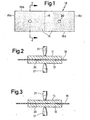
- a sheet 18 of pouch material is illustrated in a plan view.
- the material is preferably a plastic film of any of the thermoplastic polymers capable of being heat sealed to itself, such as polyethylene, polypropylene, PVC, nylon, halar, tefzel, FEP or PFA, and is, for example, approximately 0.002 inches thick.
- the sheet comprises four edges 18a, b, c and d.
- the sheet 18 is divided into two geometrically equal sections 19 by an imaginary dividing line 16.
- a through-hole 20 of, for example, 1/8 inch diameter, is punched in the center of each section 19.
- the discs are, for example, 0.010 inch thick and of greater diameter than the hole so as to contact the pouch material surrounding the hole.
- the discs 11, 12, are generally concentrically positioned to overlie the hole 20.
- the discs 11, 12, are pressed towards each other by electrodes 21 of a resistance welder with sufficient force to compress the pouch material surrounding the hole 20.
- additional compressive force is applied by the electrodes to resiliently deform the discs 11, 12, so that they contact each other through the hole 20.
- the welder is activated, bonding the discs together through the hole 20.
- the pouch material surrounding the hole 20 is held in compression between the bonded discs forming a seal..As will become clear, the pair of sealingly engaging discs form a feedthrough.
- the feedthrough-forming process is repeated at the second of the holes 20 illustrated in Figure 1 to form a second feedthrough.
- a pair of electrodes are electrically coupled to the discs 11.
- an electrode of anode material such as lithium foil is disposed directly onto the surface of one of the discs 11.
- Lithium foil is known to become "cold welded" to the surface of nickel or stainless steel members when a pressing force is exerted against the two.
- An electrode of cathode material such as, for example, carbon graphite is disposed onto the surface of the second disc 11.
- One method for coupling the graphite to the disc comprises the pressing of the graphite onto a mesh-like, electrically conductive substrate and welding, or otherwise bonding, the substrate to the surface of the second disc 11.
- the pouch material is folded along the line 16 by, for example, bringing the end 18c upward from the plane of Figure 1, and to the left so that edges 18a and 18c are generally contiguous.
- the anode and cathode are facing each other from opposing pouch walls.
- Figure 4 illustrates a side elevation view of the configuration thus formed, conveniently taken from the left end of Figure 1. Looking between edges 18a and 18c, towards the fold 16, two pair of discs 11, 12j are shown. The anode 14 and cathode 15 are coupled to respective interior discs 11. As will be clear, electrical connection to the anode and cathode will be made to respective external discs 12 which function as the terminals of the electrochemical cell.
- a piece of electrically insulative porous material (not shown) is placed between the anode and cathode to minimally separate them while permitting electrochemical coupling therebetween by an electrolyte.
- electrically insulative porous material (not shown) is placed between the anode and cathode to minimally separate them while permitting electrochemical coupling therebetween by an electrolyte.
- the pouch After placing of the separator between the anode and cathode, the pouch is substantially sealed. Specifically, the two sides 18b, 18d are respectively sealed at 22, 24, by heat sealing. Accordingly, each side 18b, 18d is placed between the jaws 23 (Fig. 5) of an impulse heat sealer to form a leak-tight seam 22, 24.
- a thin wire 33 (Figure 5) of approximately 0.5 mm diameter is inserted between the edges 18a, 18c, generally perpendicular thereto so that the wire protrudes from between the edges. The edges are then heat sealed and the wire withdrawn, leaving an opening through which the pouch will be filled with electrolyte.
- the pouch may be conveniently filled with electrolyte by inserting the pouch into a vessel with the opening immersed in a pre-measured amount of electrolyte.
- the vessel is placed in a vacuum chamber and the pressure reduced. With the reduction in chamber pressure, the pressure in the pouch is also reduced. When the chamber is subsequently vented to atmosphere, electrolyte is forced by the higher pressure into the pouch.
- edges 18a, 18c, forming the opening are heat-sealed together.
- the cell thus completed may now be interconnected to other similar cells within a battery and hermetically sealed within the battery container if desired.
- the advantages of the described cell over known prior art cells are numerous.
- the shape of the pouch for example, can be modified with very little change in components or tooling. For example, a round configuration may be provided or the dimensions changed by merely cutting or folding the sheet 18 (Figure 1) differently. Design labor and capital equipment costs due to package modification are therefore minimal.
- An important safety-related feature of the described cell is a self-limiting current feature.
- Some electrochemical systems generate a significant amount of heat and/or pressure when excessive current is drawn from the cell. Excessive current may be drawn, for example, when an internal or external short circuit condition exists.
- the flexible pouch material of the afore-described cell permits an increase in the distance between opposing internal pouch walls in response to increased internal pressure when the pouch is appropriately dimensioned.
- the electrodes attached onto the opposing feedthrough discs 11 will accordingly become further separated, increasing the internal impedance of the cell and thereby limiting the current drained. Electrochemical cells of the type susceptible to explosion under short circuit conditions will benefit from the self-limitation of current.
- the cell pouch can be held in compression by biasing means such as a spring or freon-filled bag, to maintain minimal electrode separation during normal operation.
- biasing means such as a spring or freon-filled bag
- Maximum current may be drawn with optimum utilization of the electrochemically active materials.
- the biasing means Upon a return to normal conditions, the biasing means returns the electrodes to their initial relative position after the cell has cooled sufficiently to reduce the internal pressure.
Landscapes
- Chemical & Material Sciences (AREA)
- Chemical Kinetics & Catalysis (AREA)
- Electrochemistry (AREA)
- General Chemical & Material Sciences (AREA)
- Primary Cells (AREA)
- Sealing Battery Cases Or Jackets (AREA)
- Battery Electrode And Active Subsutance (AREA)
- Secondary Cells (AREA)
Abstract
An electrochemical cell includes an anode and a cathode electrochemically coupled by an electrolyte, means such as porous electrochemically non-conductive material placed within the anode and cathode to permit minimal electrode separation, and a cell housing which can be sealed hermetically or non-hermetically.
According to the invention a novel electrochemical cell comprises a sealed non-metallic pouch of thin flexible material which forms a cell housing of deformable configuration to render the cell adaptable to varying battery configurations as well as cell shapes.
A second feature includes a novel feedthrough arrangement wherein a pair of electrically conductive members are located on respective sides of an interjacent through-hole formed in the housing material. The pair of electrically conductive members are coupled through the through-hole to form the feedthrough. A method for making these novel electrochemical cells is provided.
Description
- This invention relates to electrochemical cells. Electrochemical cells comprise an anode and a cathode electrochemically coupled by an electrolyte. Means such as porous, electrically non-conductive material is frequently placed between the anode and cathode to permit minimal electrode separation and a consequential minimum in internal cell resistance.
- Electrochemical cells also include.a cell housing which can be hermetically sealed or non-hermetically sealed. .Electrical connection is made to the anode and cathode by means of terminals on the exterior of the housing. Some types of cells include an electrically conductive housing in physical contact with one of the electrodes so that the exterior of the housing substitutes for one of the terminals.
- Those skilled in the art know that terminals are formed by feedthroughs which sealingly pass through the container. When a metal or other electrically conductive container is used, a glass-to-metal feedthrough is employed.
- Some batteries employ a number of individually contained cells which are coupled to exterior battery terminals.
- In accordance with the invention, a novel electrochemical cell and a method for making same is provided which is particularly suitable for use in a battery of the type employing one or more cells. One feature of the cell includes a sealed non-metallic pouch of thin flexible material which forms a cell housing of deformable configuration to render the cell adaptable to varying battery configurations as well as cell shapes.
- A second feature of the cell includes a novel feedthrough arrangement wherein a pair of electrically conductive members are located on respective sides of an interjacent through-hole formed in the housing material. The pair of electrically conductive members are coupled through the through-hole to form the feedthrough.
- An electrode of anode material is electrically coupled to the internally located member of one feedthrough pair. An electrode of cathode material is electrically coupled to the internally located member of the other feedthrough. The cell further includes means for separating the electrodes, as well as a volume of electrolyte electrochemically coupling the electrodes.
- Additional features of the invention are disclosed in the following Description of a Preferred Embodiment, of which the following drawing is a part..
- Figure 1 is a plan view of a quantity of pouch material for use in constructing,an electrochemical cell in accordance with the invention,
- Figure 2 and 3 are sectional elevation views in schematic taken along line 2-2 in Figure 1 and illustrating the construction of a feedthrough in accordance with the invention,
- Figure 4 is an elevation view showing the formation of the electrochemical cell in accordance with ! the invention, and ;
- Figure 5 is an elevation view in schematic showing the sealing of an electrochemical cell in accordance with the invention.
- In Figure 1, a
sheet 18 of pouch material is illustrated in a plan view. The material is preferably a plastic film of any of the thermoplastic polymers capable of being heat sealed to itself, such as polyethylene, polypropylene, PVC, nylon, halar, tefzel, FEP or PFA, and is, for example, approximately 0.002 inches thick. The sheet comprises fouredges 18a, b, c and d. - The
sheet 18 is divided into two geometricallyequal sections 19 by an imaginary dividingline 16. A through-hole 20 of, for example, 1/8 inch diameter, is punched in the center of eachsection 19. - As shown in Figure 2, a pair of electrically
conductive discs sheet 19 with one of theholes 20 interjacent the disc pair. - The discs are, for example, 0.010 inch thick and of greater diameter than the hole so as to contact the pouch material surrounding the hole. The
discs hole 20. - Figure 3, the
discs electrodes 21 of a resistance welder with sufficient force to compress the pouch material surrounding thehole 20. With the pouch material thusly held in compression, additional compressive force is applied by the electrodes to resiliently deform thediscs hole 20. Upon such contact, the welder is activated, bonding the discs together through thehole 20. The pouch material surrounding thehole 20 is held in compression between the bonded discs forming a seal..As will become clear, the pair of sealingly engaging discs form a feedthrough. The feedthrough-forming process is repeated at the second of theholes 20 illustrated in Figure 1 to form a second feedthrough. - Referencing Figure 1 for convenience and imagining the
top disc 11 of each pair to be seen respectively overlying an associatedhole 20, a pair of electrodes (not shown) are electrically coupled to thediscs 11. In the preferred embodiment, an electrode of anode material such as lithium foil is disposed directly onto the surface of one of thediscs 11. Lithium foil is known to become "cold welded" to the surface of nickel or stainless steel members when a pressing force is exerted against the two. - An electrode of cathode material (not shown) such as, for example, carbon graphite is disposed onto the surface of the
second disc 11. One method for coupling the graphite to the disc comprises the pressing of the graphite onto a mesh-like, electrically conductive substrate and welding, or otherwise bonding, the substrate to the surface of thesecond disc 11. - With the electrodes thus electrically and physically coupled to respective discs, the pouch material is folded along the
line 16 by, for example, bringing theend 18c upward from the plane of Figure 1, and to the left so thatedges - Figure 4 illustrates a side elevation view of the configuration thus formed, conveniently taken from the left end of Figure 1. Looking between
edges fold 16, two pair ofdiscs 11, 12j are shown. Theanode 14 andcathode 15 are coupled to respectiveinterior discs 11. As will be clear, electrical connection to the anode and cathode will be made to respectiveexternal discs 12 which function as the terminals of the electrochemical cell. - Prior to sealing the pouch, a piece of electrically insulative porous material (not shown) is placed between the anode and cathode to minimally separate them while permitting electrochemical coupling therebetween by an electrolyte. The use of such separates is well-known in the art and a detailed discussion of the shapes, materials and sizes is necessary to an understanding of the invention.
- After placing of the separator between the anode and cathode, the pouch is substantially sealed. Specifically, the two
sides side tight seam - Before the side opposite the fold, comprising
edges edges - The pouch may be conveniently filled with electrolyte by inserting the pouch into a vessel with the opening immersed in a pre-measured amount of electrolyte. The vessel is placed in a vacuum chamber and the pressure reduced. With the reduction in chamber pressure, the pressure in the pouch is also reduced. When the chamber is subsequently vented to atmosphere, electrolyte is forced by the higher pressure into the pouch.
- After filling with electrolyte, the unsealed portions of
edges - The cell thus completed may now be interconnected to other similar cells within a battery and hermetically sealed within the battery container if desired.
- The advantages of the described cell over known prior art cells are numerous. The shape of the pouch, for example, can be modified with very little change in components or tooling. For example, a round configuration may be provided or the dimensions changed by merely cutting or folding the sheet 18 (Figure 1) differently. Design labor and capital equipment costs due to package modification are therefore minimal.
- Owing to the simplicity of the fabrication technique, including feedthrough construction, the entire manufacturing process is easily automated.
- An important safety-related feature of the described cell is a self-limiting current feature. Some electrochemical systems generate a significant amount of heat and/or pressure when excessive current is drawn from the cell. Excessive current may be drawn, for example, when an internal or external short circuit condition exists. The flexible pouch material of the afore-described cell permits an increase in the distance between opposing internal pouch walls in response to increased internal pressure when the pouch is appropriately dimensioned. The electrodes attached onto the opposing
feedthrough discs 11 will accordingly become further separated, increasing the internal impedance of the cell and thereby limiting the current drained. Electrochemical cells of the type susceptible to explosion under short circuit conditions will benefit from the self-limitation of current. - Accordingly, the cell pouch can be held in compression by biasing means such as a spring or freon-filled bag, to maintain minimal electrode separation during normal operation. Maximum current may be drawn with optimum utilization of the electrochemically active materials. When a short circuit or other cause of excessive current drain arises, the expansion of the pouch overcomes the force generated by the biasing means. Upon a return to normal conditions, the biasing means returns the electrodes to their initial relative position after the cell has cooled sufficiently to reduce the internal pressure.
- It should be appreciated that the foregoing description is intended to be illustrative rather than restrictive. While the foregoing description of the preferred embodiment is specific as to materials, shape and combinations of features, it is recognized that many permutations and modifications may be made by those skilled in the art who have had the benefit of these teachings. The invention herein is intended to be defined solely by the claims appended hereto which, in turn, are intended to be interpreted as broadly as permitted to include all such modifications and permutations and to be limited only by the prior art.
Claims (21)
1. An electrochemical cell comprising a sealed non-metallic pouch of thin flexible material having a pair of through-holes;
two pairs of electrically conductive members, one pair overlaying each through-hole with the through-hole
being interjacent the pair, the members of each pair being coupled through the through-hole;
the pouch material surrounding each through-hole being sealed to the overlying members;
an electrode of anode material electrically coupled to internally located member of one pair;
an electrode of cathode material electrically coupled to the internal member of the second pair;
means for separating the electrodes;
and a volume of electrolyte electrochemically coupling the electrodes.
2. The cell of Claim 1 wherein the pouch material is sealingly compressed between the members of each pair.
3. The cell of Claim 2 wherein the electrically conductive members of each pair are welded together through the through-hole.
4. The cell of Claim 2 wherein the pouch is formed from plastic.
5. The cell of Claim 4 wherein the plastic is a thermoplastic polymer.
6. The cell of Claim 5 wherein the pouch is heat sealed.
7. The cell of Claim 1 wherein the through-holes are formed in opposing faces of the pouch.
8. The cell of Claim 7 wherein at least one of the anode material and cathode material is attached onto the respective interior electrically conductive member.
9. The cell of Claim 8 wherein the pouch is formed from thin flexible material dimensioned to permit pouch expansion and consequential separation of the electrodes
10. The cell of Claim 9 including biasing means for maintaining minimal separation between the electrodes while permitting increased separation between the electrodes in response to increasing pressure in the pouch.
11. A feedthrough assembly for use in an electrochemical cell comprising
a wall of thin flexible non-metallic material having a through-hole,
a pair of electrically conductive members on opposite sides of the wall and overlying the through-hole, the members holding the interjacent wall material in compression and being electrically coupled with each other through the through-hole.
12. The feedthrough assembly of Claim 11 wherein the electrically conductive members are welded together through the through-hole.
13. The feedthrough assembly of Claim 11 wherein the wall is formed from plastic.
14. The feedthrough assembly of Claim 11 wherein the electrically conductive members are formed from a material selected from stainless steel and nickel.
15. A method for assemblying an electrochemical cell comprising the steps of
(a) forming a pair of through-holes in a sheet of thin resilient non-metallic material;
(b) placing each through-hole between a respective pair of overlying electrically conductive members;
(c) sealing the members of each pair of conductive members to the non-metallic material surrounding the through-hole;
(d) electrically coupling the members of each pair through the interjacent through-hole;
(e) electrically coupling an anode and a cathode respectively to the electrically conductive member of a different member pair on one side of the non-metallic sheet;
(f) forming the non-metallic material into a pouch;
(g) providing for minimal separation of the anode and cathode;
(h) adding electrolyte in electrochemical contact with the anode and cathode; and
(i) sealing the pouch.
16. The method of Claim 15 including the step of sealingly compressing the interjacent non-metallic material surrounding the through-hole between the electrically conductive members; and
bonding the electrically conductive members together through the through-hole so that the interjacent non-metallic material is held in sealing compression therebetween.
bonding the electrically conductive members together through the through-hole so that the interjacent non-metallic material is held in sealing compression therebetween.
17. The method of Claim 16 including the step of attaching the anode and cathode onto the interior member of a respective member pair.
18. The method of Claim 17 including the step of locating the anode and cathode on opposing interior faces of the pouch.
19. The method of Claim 18 including the step of sizing the pouch to permit increased pressure within the pouch during cell operation to separate the electrodes from each other.
20. The method of Claim 19 including the step of biasing the electrodes for minimal separation during predetermined operating pressures.
21. The method of Claim 15 wherein the non-metallic material is a thermoplastic polymer and the pouch is sealed by applying heat to the plastic to form a heat-sealed seam.
Applications Claiming Priority (2)
| Application Number | Priority Date | Filing Date | Title |
|---|---|---|---|
| US06/506,786 US4507857A (en) | 1983-06-22 | 1983-06-22 | Electrochemical cell |
| US506786 | 1983-06-22 |
Publications (2)
| Publication Number | Publication Date |
|---|---|
| EP0129837A2 true EP0129837A2 (en) | 1985-01-02 |
| EP0129837A3 EP0129837A3 (en) | 1985-11-27 |
Family
ID=24016008
Family Applications (1)
| Application Number | Title | Priority Date | Filing Date |
|---|---|---|---|
| EP84107061A Withdrawn EP0129837A3 (en) | 1983-06-22 | 1984-06-20 | Electrochemical cell |
Country Status (4)
| Country | Link |
|---|---|
| US (1) | US4507857A (en) |
| EP (1) | EP0129837A3 (en) |
| JP (1) | JPS6193550A (en) |
| DK (1) | DK292384A (en) |
Cited By (1)
| Publication number | Priority date | Publication date | Assignee | Title |
|---|---|---|---|---|
| FR2589007A1 (en) * | 1985-10-04 | 1987-04-24 | Hellesens As | METHOD FOR MANUFACTURING A TERMINAL CROSSING FOR AN ELECTRIC BATTERY CONSISTING OF ELEMENTS STACKED ON EACH OTHER |
Families Citing this family (15)
| Publication number | Priority date | Publication date | Assignee | Title |
|---|---|---|---|---|
| US5670272A (en) * | 1994-03-31 | 1997-09-23 | Valence Technology, Inc. | Battery packaging for flat cell batteries having a compressing material for the cell stack |
| US6040085A (en) * | 1994-03-31 | 2000-03-21 | Valence Technology, Inc. | Battery packaging |
| US6100702A (en) * | 1997-07-25 | 2000-08-08 | 3M Innovative Properties Company | In-situ fault detection apparatus and method for an encased energy storing device |
| US5952815A (en) * | 1997-07-25 | 1999-09-14 | Minnesota Mining & Manufacturing Co. | Equalizer system and method for series connected energy storing devices |
| US6087036A (en) * | 1997-07-25 | 2000-07-11 | 3M Innovative Properties Company | Thermal management system and method for a solid-state energy storing device |
| US6104967A (en) * | 1997-07-25 | 2000-08-15 | 3M Innovative Properties Company | Fault-tolerant battery system employing intra-battery network architecture |
| US6099986A (en) * | 1997-07-25 | 2000-08-08 | 3M Innovative Properties Company | In-situ short circuit protection system and method for high-energy electrochemical cells |
| US6146778A (en) | 1997-07-25 | 2000-11-14 | 3M Innovative Properties Company | Solid-state energy storage module employing integrated interconnect board |
| US6120930A (en) * | 1997-07-25 | 2000-09-19 | 3M Innovative Properties Corporation | Rechargeable thin-film electrochemical generator |
| US6117584A (en) * | 1997-07-25 | 2000-09-12 | 3M Innovative Properties Company | Thermal conductor for high-energy electrochemical cells |
| US6235425B1 (en) | 1997-12-12 | 2001-05-22 | 3M Innovative Properties Company | Apparatus and method for treating a cathode material provided on a thin-film substrate |
| US6207318B1 (en) * | 1998-06-22 | 2001-03-27 | Eagle-Picher Energy Products Corporation | Electrochemical batteries with restricted liquid electrolyte volume |
| WO2000021614A1 (en) * | 1998-10-14 | 2000-04-20 | Williams Fire & Hazard Control, Inc. | Portable wall-attachable fire fighting apparatus and method |
| US20040115526A1 (en) * | 2001-01-26 | 2004-06-17 | Lewandowski Thongkhanh P | Laminant container with fitment |
| WO2019173485A1 (en) * | 2018-03-06 | 2019-09-12 | President And Fellows Of Harvard College | Method for fabrication of ultra lightweight, high power density lithium ion batteries |
Family Cites Families (14)
| Publication number | Priority date | Publication date | Assignee | Title |
|---|---|---|---|---|
| US1259485A (en) * | 1916-01-07 | 1918-03-19 | Thomas W Byrne | Process of making electric batteries. |
| US2272969A (en) * | 1939-01-28 | 1942-02-10 | Nat Carbon Co Inc | Galvanic battery |
| US2798895A (en) * | 1954-06-18 | 1957-07-09 | Ray O Vac Co | Point contact battery |
| US2870235A (en) * | 1956-04-09 | 1959-01-20 | Union Carbide Corp | Cathodic envelope cell |
| US3253954A (en) * | 1963-08-13 | 1966-05-31 | Gould National Batteries Inc | Retaining member for storage battery electrodes |
| DE7002943U (en) * | 1970-01-29 | 1971-07-08 | Bosch Gmbh Robert | GAS-PROOF LEAD ACCUMULATOR WITH PLASTIC CASE. |
| JPS4940716U (en) * | 1972-07-12 | 1974-04-10 | ||
| US3871921A (en) * | 1974-04-01 | 1975-03-18 | Union Carbide Corp | Flat alkaline cell construction and method for assembling the same |
| US4092464A (en) * | 1976-07-19 | 1978-05-30 | P. R. Mallory & Co. Inc. | Flexible cells and batteries formed therefrom |
| US4319708A (en) * | 1977-02-15 | 1982-03-16 | Lomerson Robert B | Mechanical bonding of surface conductive layers |
| US4321315A (en) * | 1980-05-28 | 1982-03-23 | A/S Hellesens | Alkaline battery |
| JPS5727571A (en) * | 1980-07-25 | 1982-02-13 | Shin Kobe Electric Mach Co Ltd | Manufacture of storage battery |
| FI65688C (en) * | 1981-04-27 | 1984-06-11 | Sporax Oy | CONTACT CONTROL FOR BATTERIES I ETT GALVANISKT BATTERI |
| JPS5940470A (en) * | 1982-08-30 | 1984-03-06 | Fuji Elelctrochem Co Ltd | Laminated cell |
-
1983
- 1983-06-22 US US06/506,786 patent/US4507857A/en not_active Expired - Lifetime
-
1984
- 1984-06-14 DK DK292384A patent/DK292384A/en not_active Application Discontinuation
- 1984-06-20 EP EP84107061A patent/EP0129837A3/en not_active Withdrawn
- 1984-06-21 JP JP59129022A patent/JPS6193550A/en active Pending
Cited By (2)
| Publication number | Priority date | Publication date | Assignee | Title |
|---|---|---|---|---|
| FR2589007A1 (en) * | 1985-10-04 | 1987-04-24 | Hellesens As | METHOD FOR MANUFACTURING A TERMINAL CROSSING FOR AN ELECTRIC BATTERY CONSISTING OF ELEMENTS STACKED ON EACH OTHER |
| US4891048A (en) * | 1985-10-04 | 1990-01-02 | A/S Hellesens | Method of manufacturing a terminal lead-through for a battery consisting of cells piled on each other |
Also Published As
| Publication number | Publication date |
|---|---|
| US4507857A (en) | 1985-04-02 |
| DK292384D0 (en) | 1984-06-14 |
| JPS6193550A (en) | 1986-05-12 |
| EP0129837A3 (en) | 1985-11-27 |
| DK292384A (en) | 1984-12-23 |
Similar Documents
| Publication | Publication Date | Title |
|---|---|---|
| US4507857A (en) | Electrochemical cell | |
| US6040085A (en) | Battery packaging | |
| US4900643A (en) | Lead acid bipolar battery plate and method of making the same | |
| US4505996A (en) | Primary flat cell | |
| US4525439A (en) | Connector aperture seal for a galvanic cell | |
| US6406815B1 (en) | Compact lithium ion battery and method of manufacturing | |
| AU705228B2 (en) | Prismatic high rate cell | |
| US4060670A (en) | Alkaline flat cell battery | |
| US6515449B1 (en) | Battery with lead/nugget protection insert | |
| KR100210271B1 (en) | Hermetic storage battery and manufacturing method | |
| US4554226A (en) | Flat cell battery connector seal | |
| EP1912269B1 (en) | Prismatic battery module and method for manufacturing the same | |
| RU2123742C1 (en) | Storage battery in plastic case | |
| JPH07505009A (en) | Compressible foam support for zinc-air batteries | |
| JPH0582020B2 (en) | ||
| JPH06349518A (en) | Bipolar lead-acid battery assembly method and resulting bipolar battery | |
| KR20070019728A (en) | Sealed Electrochemical Cell Housing | |
| US4816354A (en) | Alkaline cell battery and method for manufacture thereof | |
| JPH07142084A (en) | Lead-acid battery assembly method | |
| US2745894A (en) | Primary dry cell | |
| TW201906221A (en) | Battery system and method of manufacturing same | |
| JP4284719B2 (en) | Battery with spiral electrode and method for manufacturing the same | |
| JPH03190052A (en) | Battery pack | |
| US4887348A (en) | Alkalline cell battery and method for manufacture thereof | |
| US5225292A (en) | Internally folded expanded metal electrode for battery construction |
Legal Events
| Date | Code | Title | Description |
|---|---|---|---|
| PUAI | Public reference made under article 153(3) epc to a published international application that has entered the european phase |
Free format text: ORIGINAL CODE: 0009012 |
|
| AK | Designated contracting states |
Designated state(s): AT BE CH DE FR GB IT LI LU NL SE |
|
| PUAL | Search report despatched |
Free format text: ORIGINAL CODE: 0009013 |
|
| AK | Designated contracting states |
Designated state(s): AT BE CH DE FR GB IT LI LU NL SE |
|
| STAA | Information on the status of an ep patent application or granted ep patent |
Free format text: STATUS: THE APPLICATION IS DEEMED TO BE WITHDRAWN |
|
| 18D | Application deemed to be withdrawn |
Effective date: 19860728 |
|
| RIN1 | Information on inventor provided before grant (corrected) |
Inventor name: MARINCIC, NIKOLA Inventor name: EPSTEIN, JAMES |