EP0129566B1 - Ultrasonic method for measuring strains in a bolt or similar part adapted to said method - Google Patents
Ultrasonic method for measuring strains in a bolt or similar part adapted to said method Download PDFInfo
- Publication number
- EP0129566B1 EP0129566B1 EP84900015A EP84900015A EP0129566B1 EP 0129566 B1 EP0129566 B1 EP 0129566B1 EP 84900015 A EP84900015 A EP 84900015A EP 84900015 A EP84900015 A EP 84900015A EP 0129566 B1 EP0129566 B1 EP 0129566B1
- Authority
- EP
- European Patent Office
- Prior art keywords
- reflectors
- acoustic
- bolt
- measurement
- stress
- Prior art date
- Legal status (The legal status is an assumption and is not a legal conclusion. Google has not performed a legal analysis and makes no representation as to the accuracy of the status listed.)
- Expired
Links
- 238000000034 method Methods 0.000 title claims abstract description 45
- 238000005259 measurement Methods 0.000 claims abstract description 54
- 238000002592 echocardiography Methods 0.000 claims abstract 4
- 230000035882 stress Effects 0.000 claims description 56
- 230000008569 process Effects 0.000 claims description 20
- 239000000463 material Substances 0.000 claims description 15
- 230000006355 external stress Effects 0.000 claims description 3
- 230000005540 biological transmission Effects 0.000 claims description 2
- 239000000523 sample Substances 0.000 description 31
- 239000002964 rayon Substances 0.000 description 15
- 229920000297 Rayon Polymers 0.000 description 14
- 241001644893 Entandrophragma utile Species 0.000 description 10
- 238000005452 bending Methods 0.000 description 10
- 238000010168 coupling process Methods 0.000 description 7
- 238000005859 coupling reaction Methods 0.000 description 7
- 229920003023 plastic Polymers 0.000 description 7
- 239000004033 plastic Substances 0.000 description 7
- 230000008878 coupling Effects 0.000 description 6
- 229910000831 Steel Inorganic materials 0.000 description 5
- 230000000694 effects Effects 0.000 description 5
- 239000007788 liquid Substances 0.000 description 5
- 244000045947 parasite Species 0.000 description 5
- 239000010959 steel Substances 0.000 description 5
- 238000002604 ultrasonography Methods 0.000 description 5
- 230000007797 corrosion Effects 0.000 description 4
- 238000005260 corrosion Methods 0.000 description 4
- 230000003071 parasitic effect Effects 0.000 description 4
- VVQNEPGJFQJSBK-UHFFFAOYSA-N Methyl methacrylate Chemical compound COC(=O)C(C)=C VVQNEPGJFQJSBK-UHFFFAOYSA-N 0.000 description 3
- 229920005372 Plexiglas® Polymers 0.000 description 3
- 230000008901 benefit Effects 0.000 description 3
- 239000013078 crystal Substances 0.000 description 3
- 230000007935 neutral effect Effects 0.000 description 3
- 230000006835 compression Effects 0.000 description 2
- 238000007906 compression Methods 0.000 description 2
- 239000008710 crystal-8 Substances 0.000 description 2
- 235000021183 entrée Nutrition 0.000 description 2
- 238000000691 measurement method Methods 0.000 description 2
- 230000036316 preload Effects 0.000 description 2
- 239000007787 solid Substances 0.000 description 2
- 230000009897 systematic effect Effects 0.000 description 2
- 235000019687 Lamb Nutrition 0.000 description 1
- 230000002745 absorbent Effects 0.000 description 1
- 239000002250 absorbent Substances 0.000 description 1
- 238000013459 approach Methods 0.000 description 1
- 238000011088 calibration curve Methods 0.000 description 1
- 230000008859 change Effects 0.000 description 1
- 238000010276 construction Methods 0.000 description 1
- 238000012937 correction Methods 0.000 description 1
- 230000001419 dependent effect Effects 0.000 description 1
- 238000001514 detection method Methods 0.000 description 1
- 238000009826 distribution Methods 0.000 description 1
- 230000005284 excitation Effects 0.000 description 1
- 239000003302 ferromagnetic material Substances 0.000 description 1
- 239000000835 fiber Substances 0.000 description 1
- 238000002955 isolation Methods 0.000 description 1
- 238000005304 joining Methods 0.000 description 1
- 230000033001 locomotion Effects 0.000 description 1
- 238000011326 mechanical measurement Methods 0.000 description 1
- 230000035515 penetration Effects 0.000 description 1
- 230000001603 reducing effect Effects 0.000 description 1
- 230000009467 reduction Effects 0.000 description 1
- 230000002829 reductive effect Effects 0.000 description 1
- 230000002787 reinforcement Effects 0.000 description 1
- 230000000717 retained effect Effects 0.000 description 1
- 230000002441 reversible effect Effects 0.000 description 1
- 230000002459 sustained effect Effects 0.000 description 1
- 238000012360 testing method Methods 0.000 description 1
- 230000007704 transition Effects 0.000 description 1
Images

Classifications
-
- G—PHYSICS
- G01—MEASURING; TESTING
- G01L—MEASURING FORCE, STRESS, TORQUE, WORK, MECHANICAL POWER, MECHANICAL EFFICIENCY, OR FLUID PRESSURE
- G01L5/00—Apparatus for, or methods of, measuring force, work, mechanical power, or torque, specially adapted for specific purposes
- G01L5/24—Apparatus for, or methods of, measuring force, work, mechanical power, or torque, specially adapted for specific purposes for determining value of torque or twisting moment for tightening a nut or other member which is similarly stressed
- G01L5/246—Apparatus for, or methods of, measuring force, work, mechanical power, or torque, specially adapted for specific purposes for determining value of torque or twisting moment for tightening a nut or other member which is similarly stressed using acoustic waves
-
- F—MECHANICAL ENGINEERING; LIGHTING; HEATING; WEAPONS; BLASTING
- F16—ENGINEERING ELEMENTS AND UNITS; GENERAL MEASURES FOR PRODUCING AND MAINTAINING EFFECTIVE FUNCTIONING OF MACHINES OR INSTALLATIONS; THERMAL INSULATION IN GENERAL
- F16B—DEVICES FOR FASTENING OR SECURING CONSTRUCTIONAL ELEMENTS OR MACHINE PARTS TOGETHER, e.g. NAILS, BOLTS, CIRCLIPS, CLAMPS, CLIPS OR WEDGES; JOINTS OR JOINTING
- F16B31/00—Screwed connections specially modified in view of tensile load; Break-bolts
- F16B31/02—Screwed connections specially modified in view of tensile load; Break-bolts for indicating the attainment of a particular tensile load or limiting tensile load
- F16B2031/022—Screwed connections specially modified in view of tensile load; Break-bolts for indicating the attainment of a particular tensile load or limiting tensile load using an ultrasonic transducer
-
- G—PHYSICS
- G01—MEASURING; TESTING
- G01N—INVESTIGATING OR ANALYSING MATERIALS BY DETERMINING THEIR CHEMICAL OR PHYSICAL PROPERTIES
- G01N2291/00—Indexing codes associated with group G01N29/00
- G01N2291/02—Indexing codes associated with the analysed material
- G01N2291/028—Material parameters
- G01N2291/02827—Elastic parameters, strength or force
Definitions
- the present invention relates to a method for measuring the stress in a bolt or the like, in particular a high-strength bolt, a threaded rod or a tie rod, by reflection of acoustic waves.
- It also relates to bolts or the like adapted so as to be able to measure the stress by means of the method according to the invention.
- constraint should be understood to mean the cause which causes the transit time of the useful acoustic ray to vary over a route of determined length.
- the invention finds in particular applications in the measurement of the stress appearing in bolts, threaded rods and tie rods, but is not limited to these applications.
- high-strength bolts are subjected to a prestressing state during assembly so as to develop local pressure on the contact surfaces of the assembled elements capable of opposing their relative movement under the effect of external stresses.
- the propagation speeds of acoustic waves and in particular of longitudinal waves (L waves), transverse waves (T waves) and surface waves (R waves) are a function of the physical parameters of the material environment in which propagates the wave.
- L waves longitudinal waves
- T waves transverse waves
- R waves surface waves
- the speeds of the L waves, T waves and R waves are a function of the longitudinal modulus of elasticity E, the density p and the Poisson's ratio ⁇ .
- Lamb waves their propagation speed is also a function of frequency.
- the wave velocities are influenced by all the factors which influence these physical parameters and in particular by the stress and by the temperature.
- the longitudinal and transverse acoustic waves emitted by a plane crystal have, for frequencies depending on the material medium and the equivalent diameter of the emitting crystal, a directivity property which makes it possible to selectively locate anomalies reflecting all or part of the energy of the incident wave, and this as a function of the respective positions of the transmitter as well as of the receiver and of the angle of penetration of the axis of the beam into the material.
- the stress is measured either by measuring the transit time of an ultrasonic wave in the length of the body, for example of the bolt, a measurement which can be carried out by an ultrasound pulse method, or by determining the frequencies of resonance of a sustained wave.
- the resonant frequencies constitute an arithmetic progression whose reason is the fundamental frequency.
- the inverse of the latter is the minimum transit time of the useful acoustic ray.
- a measurement by transmission can be carried out by placing an ultrasonic transmitter on one side of the room and a receiver on the opposite side. It is however also possible to carry out a measurement by reflection using one or two probes which consist of a transmitter and a receiver, most often combined or separated in the same probe, the measurement then being carried out by detection of echoes resulting from reflections of the wave on the ends of the part and determination of the transit time of the useful acoustic ray, by determination of the time separating the appearance of the feet from the echo peaks of ends on the representation of type A, each reflection causing, if the reflected energy returns to the receiver, an echo of anomaly characterized by a peak in the type A representation used in conventional conventional ultrasonic testing devices.
- the classic way to determine the stress in a bolt is to adequately place a probe on one end of the bolt and measure the time required for the useful acoustic radius to travel two or a multiple of twice the length of the bolt , the acoustic ray being partially or totally reflected at the two ends of the bolt.
- the transit time in the bolt is a function of the stress on the path of the useful acoustic radius because this influences the speed of transit and the length of transit.
- the present invention therefore aims to provide a method for measuring the stress in a bolt or similar parts by taking advantage of the reflection of an acoustic ray and by measuring the transit time thereof using an apparatus. ad-hoc for example an apparatus determining the time between the feet of two characteristic echo reflection peaks while eliminating the drawbacks of known methods or reducing their impact to a greater or lesser extent.
- the method of the present invention is characterized in that one chooses in the bolt or similar part one or more ends of rectilinear measurement paths materialized by an internal artificial reflector, in that one sends a beam of acoustic waves of in such a way that acoustic rays carrying sufficient energy touch the useful reflectors, in that the echoes corresponding to the reflectors are selected, in that the transit times characteristic of the useful acoustic rays are determined by measurement to the artificial reflector internal and in that one transposes the transit times for each internal reflector considered in isolation or the respective differences in transit time of each pair of reflectors in value of external stress or in value of stress in the zone delimited by each pair of reflectors .
- a preferred practical embodiment of the invention is characterized in that one chooses in the medium a rectilinear measurement path limited by two internal artificial reflectors, in that one sends a beam of acoustic waves whose axis is substantially coincident with the rectilinear measurement path chosen, in that the echoes corresponding to the reflectors are selected, in that the transit time characteristic of an acoustic ray between the two reflectors is measured, which is the difference in transit times acoustic rays, coincident or substantially parallel to each of the two reflectors and in that the transit time values are transposed into stress values.
- the characteristic transit time is the minimum transit time.
- an apparatus will advantageously be used making it possible to select the feet of peaks due to the internal artificial reflectors and to differentiate between the two transit times of the wave from the emitting source to the corresponding reflector.
- the artificial reflectors are advantageously arranged in such a way that the path of the acoustic wave is parallel to and very close to the neutral line, or even on the latter. This arrangement makes it possible to practically eliminate the influences of bending which can distort the measurements in the current process.
- the beam used will be focused.
- the transit time can be measured by continuous emission and determination of the resonance frequencies of the wave due to the internal reflectors.
- the resonant frequencies constitute an arithmetic progression whose reason is the fundamental frequency.
- the inverse of the latter is the minimum transit time of the useful acoustic ray between the reflectors concerned.
- the measurement of the transit time of the acoustic wave between the two reflectors will advantageously be carried out by the use of a thickness meter exploiting the ultrasonic waves.
- the ultrasonic thickness measuring device can be considered as a device which directly or indirectly measures a transit time of an ultrasonic beam in the workpiece.
- the transit time t of the acoustic wave between the two internal reflectors will be measured when the body is subjected to a stress.
- transverse ultrasonic waves could be used in case the stress applied to the body during the calibration phase shows an influence on the transit time characteristic of the useful acoustic ray along the line separating the artificial internal reflectors .
- This however has several drawbacks known to those skilled in the art, in particular the difficulty of generating this type of wave in the material in the case of normal propagation at the end of the part.
- any type of acoustic wave could be used, in particular surface ultrasonic waves, provided that the stress applied to the body has an influence on the transit time characteristic of the useful acoustic ray following the stress thus created on the line separating the internal artificial reflectors.
- the internal artificial reflectors should be relatively close to the surface since the surface wave only affects a depth of the material on the order of the wavelength.
- longitudinal ultrasonic waves are used which have the advantage, in the event of normal incidence, of being easily transmitted to the part.
- a longitudinal wave and a transverse wave could also be used in combination and concomitantly or successively, which gives additional data for determining the stress.
- the ratio of the respective transit times of an L wave and a T wave in a sufficiently homogeneous and isotropic medium between two reflectors is equal to the inverse of the ratio of the respective speeds of these two waves and is only dependent on the Poisson's ratio value ⁇ . It therefore does not depend on the distance between the reflectors. It is therefore sufficient to calibrate this ratio of transit times for the material as a function of the stress. It is desirable to do this on the component with the reflectors.
- the method of the invention therefore no longer requires calibration for each position of the nut in the case of application to a bolted structure.
- An equivalent remark can be made in the case of the threaded rod and the threaded tie rod or anchored in a solid block.
- the effect of bending on the measurement is considerably reduced compared to known methods.
- the reflectors are smaller and the wave path is that connecting by a straight line the two reflectors arranged on the slightly curved neutral line.
- the error due to the difference between the length of the rope and the length of the arc formed by the neutral fiber is not appreciably modified but the useful acoustic radius propagates in a medium close to the axis of the part where the disturbing stress due to bending can usually be considered negligible while in known methods, this radius is displaced in the compression zone introduced by bending.
- the probe will advantageously always be in the same place on the head, otherwise we will not receive a signal or we will receive signals of different energy.
- This positioning is made possible by the presence of artificial internal reflectors.
- it will possibly require the use of a conventional device making it possible to display the amplitude of the peaks of the reflection echoes relating to the internal artificial reflectors in a type A or equivalent representation so as to position the probe at the location where the peaks reflection echoes of the two artificial reflectors if possible respectively identical in amplitude to the peaks obtained during the calibration.
- the transmitted acoustic energy depends inter alia on the thickness of the coupling liquid and on the pressure exerted on the probe, it is at least necessary that the relative heights of the peaks are substantially in the same ratio as during the calibration, which means that the proportions of the energy transmitted in the bolt and reflected by each reflector to the receiver are substantially identical.
- the peaks of the reflection echoes of the two artificial reflectors will be as much as possible simultaneously maximum when the beam axis is substantially coincident with the axis of the bolt.
- the reflectors are bores orthogonal to the barrel of the bolt and making between them a certain angle, it is the reflection by the second reflector on either side of the shadow created by the first.
- the presence of internal reflectors no longer requires generating and receiving the acoustic wave by contact.
- the field of application is not limited to steel.
- the artificial reflectors consist of perforations or transverse bores. These are advantageously arranged in parallel planes at an angle to each other. Preferably the two reflectors are perpendicular to each other. It may be advantageous, in the case of parts subjected to torsion, to arrange the perforations or bores at an angle between 0 ° and 90 ° and in a direction such that this angle increases with the angular deformation of torsion.
- the reflectors consist of two coaxial bores of small diameter, but of different diameter and of different depth, the difference in depth determining the exploited area of transit of the useful acoustic ray.
- the transition zone between the two bores has a sharp edge and a flat connection surface, perpendicular to the axis. It is advantageous for the acoustic wave to enter the part through the end opposite the bore. It is certainly possible to find other possibilities for reflectors and the invention is not limited to the cited cases of application, nor to the particular embodiment indicated of reflectors.
- the present invention also relates to parts characterized in that they include artificial reflectors.
- assembly elements for example, high-strength bolts, threaded rods, smooth or ribbed, rivets, studs or even structural elements, in particular beams or other construction elements.
- These parts are advantageously provided with a means for geometrical positioning of the probe on the contact face, in particular a positioning sleeve or a housing in the end of the part.
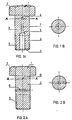
- FIG. 1 shows by way of example, a high-strength bolt 1 comprising a head 2 and a body 3 provided at its end 4 opposite the head, with a thread 5. From the end 4 of the bolt 1 , two coaxial bores 6, 7 of different diameter were machined.
- the bore 6 advantageously has a diameter greater than that of the bore 7 so as not to be masked by the "shadow" formed by the first reflector 8 formed by the bottom of the bore 7, when the probe placed on head 2 sends an ultrasonic wave through the bolt.
- the second artificial reflector is created by the shoulder 9.
- the bores are advantageously arranged on the axial line of the bolt.
- the reflectors 8 and 9 can be placed in such a way that the measurement zone is arranged only in the chosen stress zone.
- the part of the body of the bolt between the bearing surface of the head and the thread engaged in the nut is the zone in which the stress is significant.
- an apparatus intended for thickness measurements by ultrasound of the UTG 5A-IIB-SONATEST type was used which automatically calculates the difference in appearance of the peak feet of the two echoes resulting from the reflection of the useful acoustic ray on the two. artificial reflectors, by eliminating the other echoes in particular the beginning and background echo of parts and if necessary the parasitic echoes of the part beyond the second artificial reflector for example those resulting from edges and inclined surfaces of the nets .
- Figure 2 shows another way of making artificial reflectors.
- Two transverse holes were drilled in the body 3 of the bolt 1, perpendicular to the axis of the latter.
- the holes 10, 11 are advantageously in parallel planes while forming an angle relative to each other in projection on one of the planes so as to intersect by example on the axial line.
- the two perforations 10, 11 are advantageously perpendicular to each other.
- the ultrasonic waves will be reflected by the bottom of the bore 7 and by the wall of the bore 11.
- the reflectors can be positioned so that the transit time of the disturbing echoes of the nets is greater than the transit time of the useful acoustic ray reflected on the most distant artificial reflector. In this way, they are not troublesome for the measurement in the first course of the wave.
- the measurement of the temperature could be done concomitantly with the measurement of the stress by adequately embedding a temperature sensor, such as for example a thermocouple in the probe.
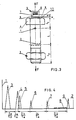
- FIG. 3 represents a bolt provided with two internal artificial reflectors in this case transverse bores 1 and 2 diametrical in two parallel planes perpendicular to the axis of the bolt.
- the bolt is provided with a nut 3.
- a probe 5 emitting and receiving ultrasound has been placed which contains a piezoelectric crystal 8, a plexiglass delay line 7, an absorbent material 6.
- the length of the path in the plexiglass is p, in the coupling liquid e, in the bolt to the first reflector 1, between the two reflectors L, between the second reflector and the end 1 2 .
- the bolt is subjected to a force F which varies the transit time characteristic of the useful acoustic radius between the two reflectors.
- the peak 3 is linked to the excitation of the crystal 8 of FIG. 3.
- Peak 4 relates to the reflection at the plexiglass-coupling liquid interface.
- Peak 5 relates to the reflection at the liquid coupling-steel interface.
- the peak 6 relates to the reflection on the reflector 1 in FIG. 3.
- the peak 7 relates to the reflection on the reflector 2 in FIG. 3.
- the peaks 8 relate to the reflections on the faces and edges of the thread.
- the peak 9 relates to the reflection on the end of the bolt.
- Cp is the speed of the ultrasonic wave in the plexiglass.
- C a is the speed of the ultrasonic order in steel.
- Each configuration of the connecting element corresponds to a straight line.
Abstract
Description
La présente invention concerne un procédé de mesure de la contrainte dans un boulon ou une pièce analogue, notamment un boulon à haute résistance, une tige filetée ou un tirant, par réflexion d'ondes acoustiques.The present invention relates to a method for measuring the stress in a bolt or the like, in particular a high-strength bolt, a threaded rod or a tie rod, by reflection of acoustic waves.
Elle concerne également des boulons ou pièces analogues adaptés de manière à pouvoir effectuer la mesure de la contrainte au moyen du procédé suivant l'invention.It also relates to bolts or the like adapted so as to be able to measure the stress by means of the method according to the invention.
Il faut entendre par contrainte dans le sens de l'invention la cause qui fait varier le temps de transit du rayon acoustique utile sur un parcours de longueur déterminée.In the sense of the invention, constraint should be understood to mean the cause which causes the transit time of the useful acoustic ray to vary over a route of determined length.
Il peut s'agir d'une variation de l'état de contrainte interne au sens usuel du terme, le long du trajet du rayon acoustique, les températures locales restant constantes ou d'un système de forces extérieures appliquées au solide qui produit une variation de l'état de contrainte interne au sens usuel du terme, le long du trajet acoustique.It can be a variation of the state of internal stress in the usual sense of the term, along the path of the acoustic ray, the local temperatures remaining constant or a system of external forces applied to the solid which produces a variation from the state of internal stress in the usual sense of the term, along the acoustic path.
Par précontrainte d'un élément, on entend une technique particulière de mise en oeuvre de l'élément, consistant à y introduire une traction ou une compresison initiale qui subsiste éventuellement avec une amplitude variable quel que soit le système des charges appliquées.By prestressing of an element, one understands a particular technique of implementation of the element, consisting in introducing into it a traction or an initial compression which possibly remains with a variable amplitude whatever the system of the applied loads.
L'invention trouve en particulier des applications dans la mesure de la contrainte apparaissant dans les boulons, les tiges filetées et les tirants, mais n'est pas limitée à ces applications.The invention finds in particular applications in the measurement of the stress appearing in bolts, threaded rods and tie rods, but is not limited to these applications.
La particularité des boulons à haute résistance réside dans le fait qu'ils sont soumis lors du montage à un état de précontrainte de façon à développer sur les surfaces de contact des éléments assemblés une pression locale capable de s'opposer à leur mouvement relatif sous l'effet de sollicitations extérieures.The special feature of high-strength bolts is that they are subjected to a prestressing state during assembly so as to develop local pressure on the contact surfaces of the assembled elements capable of opposing their relative movement under the effect of external stresses.
D'où l'importance de pouvoir contrôler et mesurer la précontrainte introduite dans le corps du boulon lors du serrage.Hence the importance of being able to check and measure the preload introduced into the bolt body during tightening.
Les techniques de mesure mécanique comme, par exemple, clé dynamométrique, notamment pour la mesure de la précontrainte lors du serrage, s'étant avérées trop imprécises et ne permettant que diffilement des mesures échelonnées dans le temps de la précontrainte résiduelle, on a recherché d'autres solutions.Mechanical measurement techniques such as, for example, a torque wrench, in particular for the measurement of the prestress during tightening, having proved to be too imprecise and only allowing diffused measurements over time of the residual prestress, we have sought to other solutions.
Aussi certains auteurs ont proposé une mesure de contrainte par des ondes acoustiques.Also some authors have proposed a measurement of stress by acoustic waves.
En effet, on sait que les vitesses de propagation des ondes acoustiques et en particulier des ondes longitudinales (ondes L) , des ondes transversales (ondes T) et des ondes de surface (ondes R) sont fonction des paramètres physiques du milieu matériel dans lequel se propage l'onde. A titre d'exemple pour un milieu homogène et isotrope, les vitesses des ondes L, des ondes T et des ondes R sont fonction du module longitudinal d'élasticité E, de la densité p et du coefficient de Poisson µ. Quant aux ondes de Lamb, leur vitesse de propagation est de plus fonction de la fréquence. Les vitesses des ondes sont influencées par tous les facteurs qui influencent ces paramètres physiques et en particulier par la contrainte et par la température.Indeed, we know that the propagation speeds of acoustic waves and in particular of longitudinal waves (L waves), transverse waves (T waves) and surface waves (R waves) are a function of the physical parameters of the material environment in which propagates the wave. For example, for a homogeneous and isotropic medium, the speeds of the L waves, T waves and R waves are a function of the longitudinal modulus of elasticity E, the density p and the Poisson's ratio µ. As for Lamb waves, their propagation speed is also a function of frequency. The wave velocities are influenced by all the factors which influence these physical parameters and in particular by the stress and by the temperature.
Les ondes acoustiques longitudinales et transversales émises par un cristal plan présentent pour des fréquences dépendant du milieu matériel et du diamètre équivalent du cristal émetteur, une propriété de directivité qui permet de localiser sélectivement les anomalies réfléchissant tout ou une partie de l'énergie de l'onde incidente, et ce en fonction des positions respectives de l'émetteur ainsi que du récepteur et de l'angle de pénétration de l'axe du faisceau dans le matériau.The longitudinal and transverse acoustic waves emitted by a plane crystal have, for frequencies depending on the material medium and the equivalent diameter of the emitting crystal, a directivity property which makes it possible to selectively locate anomalies reflecting all or part of the energy of the incident wave, and this as a function of the respective positions of the transmitter as well as of the receiver and of the angle of penetration of the axis of the beam into the material.
Dans les procédés connus, on mesure la contrainte soit par une mesure du temps de transit d'une onde ultrasonore dans la longueur du corps, par exemple du boulon, mesure qui peut être réalisée par une méthode impulsionnelle échographique, soit par la détermination des fréquences de résonance d'une onde entretenue. Les fréquences de résonance constituent une progression arithmétique dont la raison est la fréquence fondamentale. L'inverse de cette dernière est le temps de transit minimum du rayon acoustique utile.In known methods, the stress is measured either by measuring the transit time of an ultrasonic wave in the length of the body, for example of the bolt, a measurement which can be carried out by an ultrasound pulse method, or by determining the frequencies of resonance of a sustained wave. The resonant frequencies constitute an arithmetic progression whose reason is the fundamental frequency. The inverse of the latter is the minimum transit time of the useful acoustic ray.
Généralement la mesure de la contrainte par ultrasons exploite cependant la mesure directe du temps de transit d'une onde longitudinale ou d'une onde transversale.Generally the measurement of the stress by ultrasound, however, exploits the direct measurement of the transit time of a longitudinal wave or a transverse wave.
A cet effet on peut effectuer une mesure par transmission en plaçant un émetteur d'ultrasons d'un côté de la pièce et un récepteur du côté opposé. On peut cependant également effectuer une mesure par réflexion en utilisant un ou deux palpeurs qui consistent en un émetteur et un récepteur, le plus souvent combinés ou séparés dans un même palpeur, la mesure étant alors effectuée par détection d'échos résultant de réflexions de l'onde sur les extrémités de la pièce et détermination du temps de transit du rayon acoustique utile, par détermination du temps séparant l'apparition des pieds des pics d'écho d'éxtrémités sur la représentation de type A, chaque réflexion provoquant en effet, si l'énergie réfléchie revient au récepteur, un écho d'anomalie caractérisé par un pic dans la représentation de type A utilisée dans les appareils conventionnels courants de contrôle par ultrasons.For this purpose, a measurement by transmission can be carried out by placing an ultrasonic transmitter on one side of the room and a receiver on the opposite side. It is however also possible to carry out a measurement by reflection using one or two probes which consist of a transmitter and a receiver, most often combined or separated in the same probe, the measurement then being carried out by detection of echoes resulting from reflections of the wave on the ends of the part and determination of the transit time of the useful acoustic ray, by determination of the time separating the appearance of the feet from the echo peaks of ends on the representation of type A, each reflection causing, if the reflected energy returns to the receiver, an echo of anomaly characterized by a peak in the type A representation used in conventional conventional ultrasonic testing devices.
La manière classique de procéder pour déterminer la contrainte dans un boulon consiste à disposer, de manière adéquate, un palpeur sur une extrémité du boulon et de mesurer le temps nécessaire au rayon acoustique utile pour parcourir deux ou un multiple de deux fois la longueur du boulon, le rayon acoustique étant réfléchi partiellement ou totalement aux deux extrémités du boulon.The classic way to determine the stress in a bolt is to adequately place a probe on one end of the bolt and measure the time required for the useful acoustic radius to travel two or a multiple of twice the length of the bolt , the acoustic ray being partially or totally reflected at the two ends of the bolt.
Le temps de transit dans le boulon est fonction de la contrainte sur le trajet du rayon acoustique utile car celle-ci influence la vitesse de transit et la longueur du transit.The transit time in the bolt is a function of the stress on the path of the useful acoustic radius because this influences the speed of transit and the length of transit.
Le procédé classique présente cependant de nombreux inconvénients:
- - le composant mécanique par exemple un boulon ne présente pas une contrainte uniforme sur la longueur parcourue par l'onde acoustique. Dans le cas du boulon precontraint, le fût ête est soumise à un effort complexe comprenant de la flexion, la zone filetée est soumise à de la traction variable et la partie libre éventuelle de la tige filetée est sans contrainte.
- - the mechanical component for example a bolt does not have a uniform stress on the length traveled by the acoustic wave. In the case of the prestressed bolt, the barrel head is subjected to a complex force including bending, the threaded zone is subjected to variable traction and the possible free part of the threaded rod is without constraint.
Il en résulte une imprécision de connaissance de la longueur de la partie tendue du boulon où la vitesse de propagation des ondes acoustiques est influencée par la contrainte et de la longueur totale du boulon dont une partie seulement est soumise à une contrainte. Une erreur systématique est donc commise lors de la détermination de la contrainte par onde acoustique sauf étalonnage dans une configuration identique. Ceci exige donc un étalonnage pour chaque position de l'écrou sur la tige filetée et chaque longueur de boulon ;
- - dans un assemblage, il est rare que les surfaces d'appui de la tête du boulon et de l'écrou soient rigoureusement planes et parallèles. Il s'ensuit une flexion du fût du boulon lors du serrage qui change le rayon acoustique utile pour la mesure et modifie du fait de la flexion seule, la longueur du trajet caractéristique. Cet inconvénient introduit du fait de ce qui precède une première erreur systématique dans la mesure de la contrainte par onde acous tique. En outre, la contrainte locale introduite par la flexion sur le trajet du rayon acoustique utile modifie la vitesse de propagation du rayon acoustique utile et de ce fait fausse la mesure de la précontrainte du boulon. Le manque de parallélisme des extrémités du boulon ou de la tige filetée dû à la flexion peut avoir pour conséquence que l'énergie acoustique réfléchie n'atteigne pas le récepteur et rende toute mesure impossible lorsqu'on effectue la mesure par réflexion.
- - Si les deux extrémités d'une pièce étroite tout en ayant des surfaces planes et parallèles ne sont pas suffisamment perpendiculaires à l'axe, bien qu'il soit possible de propager une onde acoustique dans le matériau, dans le cas où la pièce étroite présente une longueur importante, il peut être difficile voire impossible de faire parvenir par réflexion sur une extrémité un rayon acoustique utile au récepteur, ce qui rend la mesure de la contrainte impossible.
- - Le positionnement exact du palpeur sur l'extrémité du boulon a de l'importance si les surfaces réfléchissantes ne sont pas rigoureusement parallèles ou ne sont pas d'une planéité parfaite. En effet, on exploite l'information fournie par le rayon acoustique de l'onde de réflexion qui atteint le récepteur et qui présente avantageusement le temps de transit le plus faible dans la pièce. Ce temps de transit minimum est alors fonction de la position du palpeur sur les extrémités de la pièce. La largeur et l'ouverture du faisceau ont de l'importance car des rayons acoustiques peuvent être réfléchis par des réflecteurs parasites par exemple les arêtes et les faces des filets avant que le rayon acoustique utile ne soit réfléchi par la seconde extrémité de la pièce. La hauteur des pics des échos parasites peut gêner la selection des pics des échos utiles. De plus si il y a superposition des pics des échos parasites et des pics des échos utiles, il n'est plus possible de déterminer avec grande précision le temps minimum de transit du rayon utile surtout si l'on exploite un trajet ou un ensemble de trajets du rayon acoustique autre que le premier trajet. Le temps minimum de trajet se détermine en effet de manière idéale par la détermination du temps séparant les pieds des pics des échos retenus.
- - La concavité ou convexité de l'extrémité du boulon fausse la mesure du temps de transit minimum du rayon acoustique utile pour des positions différentes du palpeur sur la tête pour les mêmes raisons que ci-dessus.
- - Les attaques par corrosion généralisées de la tête et de l'extrémité du boulon font varier la longueur de reférence, c'est-à-dire le trajet du rayon qui a le plus court temps de transit. De plus, les surfaces de la tête et de l'extrémité du boulon peuvent être détériorées en service par exemple par usure, par matage, par corrosion généralisée ou localisée, de telle façon que la position relative du palpeur par rapport à la pièce ait changé. Dans les méthodes courantes de mesure de la contrainte dans les boulons, il n'est pas permis de rectifier les extrémités pour pouvoir réaliser les mesures. La rectification entraîne en effet, une diminution non quantifiable de la longueur de transit.
- - Un couplage est habituellement nécessaire entre le ou les palpeurs et la pièce pour transmettre à celle-ci une partie de l'énergie acoustique de l'émetteur et pour recueillir au récepteur une partie de l'énergie réfléchie. L'épaisseur du film du couplant entre le ou les palpeurs et la pièce influence la mesure du temps de transit de l'onde acoustique dans le cas où l'on exploite le premier trajet des ondes acoustiques dans la pièce. En effet, le pic de réflexion de la face inférieure du palpeur recouvre le pic de réflexion à l'entrée dans la pièce. Le temps de transit dans le couplant est alors compté comme faisant partie du temps de transit dans la pièce. Etant donné que pour les dimensions courantes de boulons, les variations du temps de transit exploitées pour la mesure de la contrainte sont faibles, l'erreur faite sur le temps de transit du boulon à cause du temps de transit dans le couplant peut entraîner une grande erreur sur la contrainte.
- - In an assembly, it is rare that the bearing surfaces of the head of the bolt and the nut are strictly flat and parallel. It follows a bending of the barrel of the bolt during tightening which changes the acoustic radius useful for the measurement and modifies, due to the bending alone, the length of the characteristic path. This drawback introduces due to the above a first systematic error in the measurement of the stress by acoustic wave. In addition, the local stress introduced by bending on the path of the useful acoustic ray modifies the speed of propagation of the useful acoustic ray and thereby falsifies the measurement of the preload of the bolt. The lack of parallelism of the ends of the bolt or of the threaded rod due to bending can have the consequence that the reflected acoustic energy does not reach the receiver and makes any measurement impossible when the measurement is made by reflection.
- - If the two ends of a narrow part while having flat and parallel surfaces are not sufficiently perpendicular to the axis, although it is possible to propagate an acoustic wave in the material, in the case where the narrow part has a considerable length, it may be difficult or even impossible to send a reflection ray at one end which is useful to the receiver, making measurement of the stress impossible.
- - The exact positioning of the probe on the end of the bolt is important if the reflecting surfaces are not strictly parallel or are not perfectly flat. In fact, the information provided by the acoustic ray of the reflection wave which reaches the receiver and which advantageously has the lowest transit time in the room is used. This minimum transit time is then a function of the position of the probe on the ends of the part. The width and the opening of the beam are important because acoustic rays can be reflected by parasitic reflectors for example the edges and the faces of the nets before the useful acoustic ray is reflected by the second end of the part. The height of the spurious echo peaks can hinder the selection of the peaks of the useful echoes. In addition, if there is a superposition of the peaks of the parasitic echoes and of the peaks of the useful echoes, it is no longer possible to determine with great precision the minimum transit time of the useful radius, especially if a path or a set of paths of the acoustic ray other than the first path. The minimum journey time is in fact ideally determined by determining the time separating the feet from the peaks of the echoes retained.
- - The concavity or convexity of the end of the bolt distorts the measurement of the minimum transit time of the useful acoustic radius for different positions of the probe on the head for the same reasons as above.
- - The generalized corrosion attacks of the head and of the end of the bolt vary the reference length, that is to say the path of the spoke which has the shortest transit time. In addition, the surfaces of the head and of the end of the bolt can be deteriorated in service, for example by wear, by matting, by generalized or localized corrosion, in such a way that the relative position of the probe relative to the part has changed. . In the current methods of measuring the stress in bolts, it is not allowed to rectify the ends to be able to carry out the measurements. The rectification results in fact in an unquantifiable reduction in the transit length.
- - A coupling is usually necessary between the probe (s) and the part to transmit a part of the acoustic energy from the transmitter to the latter and to collect a part of the reflected energy to the receiver. The thickness of the film of the coupler between the probe (s) and the part influences the measurement of the transit time of the acoustic wave in the case where the first path of the acoustic waves is used in the part. In fact, the reflection peak on the underside of the probe covers the reflection peak when entering the room. The transit time in the coupler is then counted as part of the transit time in the room. Since for the current dimensions of bolts, the variations in transit time used for stress measurement are small, the error made on the transit time of the bolt because of the transit time in the coupler can cause a large constraint error.
La pression de contact palpeur-pièce a donc une important ce puisqu'elle modifie l'épaisseur du film du couplant.
- - Des auteurs proposent d'éliminer les influences dûes à l'entrée de l'onde dans le matériel en mesurant le temps nécessaire à l'onde pour parcourir plusieurs fois la longueur du boulon tout en éliminant le premier parcours. Cette manière de procéder n'est en principe applicable qu'avec des palpeurs où l'émetteur et le récepteur sont combinés et non avec le ou les palpeurs à émetteur et récepteur séparés. Elle peut cependant se heurter aux difficultés dues aux échos parasites provenant entre autres, des réflexions éventuelles sur les faces et les angles des filets. Les pics parasites dûs aux réflexions sur les filets entâchent la mesure d'imprécision car il pourra ne pas être possible de déterminer avec l'exactitude nécessaire le temps minimum de transit du rayon acoustique entre les surfaces réfléchissantes caractéristiques. Dans ces cas, les autres inconvénients ne sont toujours pas éliminés.
- - Authors propose to eliminate the influences due to the entry of the wave in the material by measuring the time necessary for the wave to travel several times the length of the bolt while eliminating the first course. This procedure is in principle only applicable with probes where the transmitter and the receiver are combined and not with the probe (s) with separate transmitter and receiver. However, it can come up against difficulties due to parasitic echoes coming from, among other things, possible reflections on the faces and angles of the nets. Spurious peaks due to reflections on the nets affect the measurement of imprecision because it may not be possible to determine with the necessary accuracy the minimum transit time of the acoustic ray between the characteristic reflecting surfaces. In these cases, the other disadvantages are still not eliminated.
On a également proposé selon GB-A-1 369 858 de mesurer une force axiale, notamment dans un boulon en exploitant la fréquence de résonance naturelle de l'objet subissant la mesure sous l'effet des différentes oscillations forcées.It has also been proposed according to GB-A-1 369 858 to measure an axial force, in particular in a bolt by exploiting the natural resonant frequency of the object undergoing the measurement under the effect of the different forced oscillations.
La présente invention vise donc à fournir un procédé de mesure de la contrainte dans un boulon ou pièces analogue en mettant à profit la réflexion d'un rayon acoustique et en mesurant le temps de transit de celui-ci à l'aide d'un appareillage ad-hoc par exemple un appareillage déterminant le temps entre les pieds de deux pics de réflexion d'échos caractéristiques tout en éliminant les inconvénients des procédés connus ou en réduisant tout ou moins fortement leur impact.The present invention therefore aims to provide a method for measuring the stress in a bolt or similar parts by taking advantage of the reflection of an acoustic ray and by measuring the transit time thereof using an apparatus. ad-hoc for example an apparatus determining the time between the feet of two characteristic echo reflection peaks while eliminating the drawbacks of known methods or reducing their impact to a greater or lesser extent.
Le procédé, de la présente invention est caractérisé en ce qu'on choisit dans le boulon ou pièce analogue une ou plusieurs fins de trajets rectilignes de mesure matérialisées par un réflecteur artificiel interne, en ce qu'on envoie un faisceau d'ondes acoustiques de telle façon que des rayons acoustiques porteurs d'énergie suffisante touchent les réflecteurs utiles, en ce qu'on sélectionne les échos correspondants aux réflecteurs, en ce qu'on détermine par mesure les temps de transit caractéristiques des rayons acoustiques utiles jusqu'au réflecteur artificiel interne et en ce qu'on transpose les temps de transit pour chaque réflecteur interne considéré isolément ou les différences respectives de temps de transit de chaque couple de réflecteurs en valeur de contrainte extérieure ou en valeur de contrainte dans la zone délimitée par chaque couple de réflecteurs.The method of the present invention is characterized in that one chooses in the bolt or similar part one or more ends of rectilinear measurement paths materialized by an internal artificial reflector, in that one sends a beam of acoustic waves of in such a way that acoustic rays carrying sufficient energy touch the useful reflectors, in that the echoes corresponding to the reflectors are selected, in that the transit times characteristic of the useful acoustic rays are determined by measurement to the artificial reflector internal and in that one transposes the transit times for each internal reflector considered in isolation or the respective differences in transit time of each pair of reflectors in value of external stress or in value of stress in the zone delimited by each pair of reflectors .
Une forme d'exécution pratique préférée de l'invention est caractérisée en ce qu'on choisit dans le milieu un trajet rectiligne de mesure limité par deux réflecteurs artificiels internes, en ce qu on envoie un faisceau d'ondes acoustiques dont l'axe est substantiellement confondu avec le trajet rectiligne de mesure choisi, en ce qu'on sélectionne les échos correspondants aux réflecteurs, en ce qu'on mesure le temps de transit caractéristique d'un rayon acoustique entre les deux réflecteurs qui est la différence des temps de transit des rayons acoustiques, confondus ou substantiellement parallèles jusqu'à chacun des deux réflecteurs et en ce qu'on transpose les valeurs de temps de transit en valeurs de contrainte.A preferred practical embodiment of the invention is characterized in that one chooses in the medium a rectilinear measurement path limited by two internal artificial reflectors, in that one sends a beam of acoustic waves whose axis is substantially coincident with the rectilinear measurement path chosen, in that the echoes corresponding to the reflectors are selected, in that the transit time characteristic of an acoustic ray between the two reflectors is measured, which is the difference in transit times acoustic rays, coincident or substantially parallel to each of the two reflectors and in that the transit time values are transposed into stress values.
Avantageusement, le temps de transit caractéristique est le temps de transit minimum.Advantageously, the characteristic transit time is the minimum transit time.
Dans le but de la mesure, on utilisera avantageusement un appareillage permettant de sélectionner les pieds de pics dus aux réflecteurs artificiels internes et de faire la différence entre les deux temps de transit de l'onde depuis la source émettrice jusqu'au réflecteur correspondant.For the purpose of the measurement, an apparatus will advantageously be used making it possible to select the feet of peaks due to the internal artificial reflectors and to differentiate between the two transit times of the wave from the emitting source to the corresponding reflector.
Les réflecteurs artificiels sont avantageusement disposés de manière telle que le trajet de l'onde acoustique soit parallèle à et très proche de la ligne neutre, soit même sur celle-ci. Cette disposition permet de pratiquement éliminer les influences de la flexion qui peut fausser les mesures dans le procédé courant.The artificial reflectors are advantageously arranged in such a way that the path of the acoustic wave is parallel to and very close to the neutral line, or even on the latter. This arrangement makes it possible to practically eliminate the influences of bending which can distort the measurements in the current process.
On travaille de préférence avec un faisceau ultrasonore suffisamment étroit qui augmente la précision de la mesure, si on le combine avec des reflecteurs pratiquement ponctuels ou ayant un comportement pratiquement assimilable à un réflecteur ponctuel. Avantageusementle faisceau utilisé sera focalisé.It is preferable to work with a sufficiently narrow ultrasonic beam which increases the accuracy of the measurement, if it is combined with practically point reflectors or having a behavior practically comparable to a point reflector. Advantageously, the beam used will be focused.
La mesure du temps de transit peut être effectuée par une émission continue et détermination des fréquences de résonance de l'onde dues aux reflecteurs internes. Les fréquences de résonance constituent une progression arithmétique dont la raison est la fréquence fondamentale. L'inverse de cette dernière est le temps de transit minimum du rayon acoustique utile entre les réflecteurs concernés. On profilera avantageusement l'extrémité du boulon par exemple de façon convexe ou concave pour éliminer la fréquence de résonance liée à la longueur du boulon.The transit time can be measured by continuous emission and determination of the resonance frequencies of the wave due to the internal reflectors. The resonant frequencies constitute an arithmetic progression whose reason is the fundamental frequency. The inverse of the latter is the minimum transit time of the useful acoustic ray between the reflectors concerned. Advantageously profile the end of the bolt, for example convex or concave to eliminate the resonance frequency related to the length of the bolt.
De préférence, la mesure du temps de transit de l'onde acoustique entre les deux réflecteurs sera avantageusement effectuée par l'emploi d'un mesureur d'épaisseur exploitant les ondes ultrasonores. En fait l'appareil mesureur d'épaisseur par ultrasons peut être considéré comme un appareil qui mesure de manière directe ou indirecte un temps de transit d'un rayon ultrasonore dans la pièce.Preferably, the measurement of the transit time of the acoustic wave between the two reflectors will advantageously be carried out by the use of a thickness meter exploiting the ultrasonic waves. In fact, the ultrasonic thickness measuring device can be considered as a device which directly or indirectly measures a transit time of an ultrasonic beam in the workpiece.
Il faut donc mesurer le temps to de transit du rayon acoustique utile entre les deux réflecteurs artificiels internes lorsque le corps n'est pas soumis à une contrainte.It is therefore necessary to measure the time t o of transit of the useful acoustic ray between the two internal artificial reflectors when the body is not subjected to a stress.
Ensuite, on effectuera la mesure du temps t de transit de l'onde acoustique entre les deux réflecteurs internes lorsque le corps est soumis à une contrainte.Next, the transit time t of the acoustic wave between the two internal reflectors will be measured when the body is subjected to a stress.
La différence entre t et to est due:
- 1° à la variation de la vitesse de l'onde acoustique avec la contrainte sur le trajet du rayon acoustique utile,
- 2° à la variation de la distance caractéristique entre les réflecteurs internes du fait de la contrainte.
- 1 ° to the variation of the speed of the acoustic wave with the stress on the path of the useful acoustic ray,
- 2 ° to the variation of the characteristic distance between the internal reflectors due to the constraint.
Il est nécessaire d'établir une courbe d'étalonnage reliant la contrainte au temps t de transit entre les deux réflecteurs internes et permettant de transposer les valeurs de temps de transit en valeurs de contrainte.It is necessary to establish a calibration curve connecting the stress to the transit time t between the two internal reflectors and allowing to transpose the transit time values into constraint values.
Suivant une variante opératoire, on pourrait utiliser des ondes ultrasonores transversales au cas ou la contrainte appliquée au corps lors de la phase d'étalonnage montrerait une influence sur le temps de transit caractéristique du rayon acoustique utile le long de la ligne séparant les réflecteurs internes artificiels. Ceci présente cependant plusieurs inconvénients connus par l'homme de l'art notamment la difficulté de générer ce type d'ondes dans le matériau dans le cas d'une propagation normale à l'extrémité de la pièce.According to an operating variant, transverse ultrasonic waves could be used in case the stress applied to the body during the calibration phase shows an influence on the transit time characteristic of the useful acoustic ray along the line separating the artificial internal reflectors . This however has several drawbacks known to those skilled in the art, in particular the difficulty of generating this type of wave in the material in the case of normal propagation at the end of the part.
Suivant une variante opératoire, on pourrait utiliser tout type d'ondes acoustiques, en particulier, des ondes ultrasonores de surface, pourvu que la contrain te appliquée au corps ait une influence sur le temps de transit caractéristique du rayon acoustique utile suite à la contrainte ainsi créée sur la ligne séparant les réflecteurs internes artificiels. Dans ce cas, les réflecteurs internes artificiels devraient être relativement proches de la surface puisque l'onde de surface n'affecte qu'une profondeur du matériau de l'ordre de la longueur d'onde.According to an operating variant, any type of acoustic wave could be used, in particular surface ultrasonic waves, provided that the stress applied to the body has an influence on the transit time characteristic of the useful acoustic ray following the stress thus created on the line separating the internal artificial reflectors. In this case, the internal artificial reflectors should be relatively close to the surface since the surface wave only affects a depth of the material on the order of the wavelength.
Suivant une autre variante opératoire particulièrement préférée pour le cas des boulons, tiges filetées et tirants, on utilise des ondes ultrasonores longitudinales qui ont l'avantage en cas d'incidence normale d'être facilement transmises à la pièce.According to another operating variant which is particularly preferred for the case of bolts, threaded rods and tie rods, longitudinal ultrasonic waves are used which have the advantage, in the event of normal incidence, of being easily transmitted to the part.
On pourrait également utiliser en combinaison et concomittement ou successivement une onde longitudinale et une onde transversale, ce qui donne une donnée supplémentaire pour déterminer la contrainte.A longitudinal wave and a transverse wave could also be used in combination and concomitantly or successively, which gives additional data for determining the stress.
Le rapport des temps de transit respectifs d'une onde L et d'une onde T dans un milieu suffisamment homogène et isotrope entre deux réflecteurs es t égal à l'inverse du rapport des vitesses respectives de ces deux ondes et est uniquement dépendant de la valeur du coefficient de Poisson µ. Il ne dépend donc pas de la distance entre les réflecteurs. Il suffit donc d'étalonner ce rapport des temps de transit pour le matériau en fonction de la contrainte, Il est souhaitable de le faire sur le composant avec les réflecteurs.The ratio of the respective transit times of an L wave and a T wave in a sufficiently homogeneous and isotropic medium between two reflectors is equal to the inverse of the ratio of the respective speeds of these two waves and is only dependent on the Poisson's ratio value µ. It therefore does not depend on the distance between the reflectors. It is therefore sufficient to calibrate this ratio of transit times for the material as a function of the stress. It is desirable to do this on the component with the reflectors.
Dans d'autres cas - milieux non-homogènes ou anisotropes - par exemple, lorsque les étalonnages avec chaque type d'onde sont appliqués au composant comportant les deux réflecteurs artificiels internes, il est possible de tenir compte éventuellement des autres facteurs influençant le temps de transit de l'onde dans le matériau, comme la température par exemple.In other cases - non-homogeneous or anisotropic media - for example, when the calibrations with each wave type are applied to the component comprising the two internal artificial reflectors, it is possible to take into account possibly the other factors influencing the time of transit of the wave in the material, such as temperature for example.
La mesure de la contrainte par ultrasons dans le domaine plastique n'est possible que si l'on peut s'affranchir de l'augmentation non- réversible de distances entre deux réflecteurs. Une façon d'y parvenir est d'utiliser en combinaison et concomitamment ou successivement une onde L et une onde T pour autant que le rapport des deux temps de transit ne dépende pas notablement des déformations plastiques, ce qui permet dans les milieux suffisamment homogènes et isotropes de s'affranchir de la distance instantanée entre les réflecteurs. Cette solution pourrait vraisemblablement être étendue au cas des milieux non-homogènes et/ou anisotropes.The measurement of the stress by ultrasound in the plastic field is only possible if one can overcome the non-reversible increase in distances between two reflectors. One way of achieving this is to use in combination and concomitantly or successively an L wave and a T wave provided that the ratio of the two transit times does not depend significantly on plastic deformations, which allows in sufficiently homogeneous and isotropic to overcome the instantaneous distance between the reflectors. This solution could probably be extended to the case of non-homogeneous and / or anisotropic media.
On peut espérer résoudre également ces problèmes en utilisant deux ondes de même type ou non et de fréquence différente et d'exploiter l'éventuelle influence de la fréquence sur la vitesse de propagation pour permettre de la même façon et avec la même limitation de mesurer la contrainte dans le domaine plastique.We can also hope to solve these problems by using two waves of the same type or not and of different frequency and to exploit the possible influence of the frequency on the propagation speed to allow in the same way and with the same limitation to measure the constraint in the plastic field.
Dans ce cas, on pourrait indirectement à l'aide de courbes d'étalonnages ad-hoc faites sur le matériau, déterminer tant pour la première solution que pour la seconde, l'amplitude de la déformation plastique, en se trouvant dans le cas d'une jauge qui est simultanément jauge de contrainte et une jauge de déformation plastique.In this case, one could indirectly using ad-hoc calibration curves made on the material, determine both for the first solution and for the second, the amplitude of the plastic deformation, being in the case of '' a gauge which is simultaneously a strain gauge and a plastic strain gauge.
On pourrait également utiliser en combinaison et concomitemment ou successivement deux ou plusieurs ondes acoustiques de fréquence différente au cas où, dans un milieu réel, la vitesse d'une onde acoustique serait influencée suffisamment par la fréquence de l'onde, ce qui donnerait une ou plusieurs données supplémentaires à l'étalonnage pour déterminer la contrainte.One could also use in combination and concomitantly or successively two or more acoustic waves of different frequency in the case where, in a real medium, the speed of an acoustic wave is sufficiently influenced by the frequency of the wave, which would give one or more several additional data to the calibration to determine the stress.
On pourrait donc ainsi s'affranchir de la connaissance de la distance entre deux réflecteurs internes ou tenir compte d'autres facteurs influençant le temps de transit de l'onde dans le matériau, comme la température ou éventuellement la déformation plastique, par exemple. En choisissant un trajet caractéristique soumis à une contrainte uniforme, on élimine les zones non intéressantes et pertubatrices pour la mesure. Ce procédé permet donc, dans le cas où l'étalonnage n'a pas été effectué dans une configuration identique de la tige filetée et de l'écrou, d'éliminer du trajet caractéristique du rayon acoustique, les zones sans contrainte et/ou soumises à une contrainte non uniforme qui sont une cause d'erreur sur la mesure de la contrainte du fait que la répartition des contraintes y est mal définie et qu'elle influence le temps de transit en affectant la vitesse de l'onde et la longueur du trajet caractéristique.We could thus get rid of the knowledge of the distance between two internal reflectors or take into account other factors influencing the transit time of the wave in the material, such as temperature or possibly plastic deformation, for example. By choosing a characteristic path subjected to a uniform stress, the non-interesting and disturbing zones for the measurement are eliminated. This method therefore makes it possible, in the case where the calibration has not been carried out in an identical configuration of the threaded rod and the nut, to eliminate from the characteristic path of the acoustic ray, the zones without stress and / or subjected to a non-uniform stress which are a cause of error in the measurement of the stress because the distribution of the stresses is poorly defined and that it influences the transit time by affecting the speed of the wave and the length of the characteristic path.
Le procédé de l'invention n'exige donc plus d'étalonnage pour chaque position de l'écrou dans le cas de l'application à une structure boulonnée. Une remarque équivalente peut être faite dans le cas de la tige filetée et du tirant fileté ou ancré dans un massif.The method of the invention therefore no longer requires calibration for each position of the nut in the case of application to a bolted structure. An equivalent remark can be made in the case of the threaded rod and the threaded tie rod or anchored in a solid block.
Même si les surfaces d'appui de la tête du boulon et de l'écrou ne sont pas parallèles du fait de la flexion, l'effet de la flexion sur la mesure est considérablement réduit par rapport aux procédés connus. En effet, les réflecteurs sont plus petits et le trajet des ondes est celui reliant par une droite les deux réflecteurs disposés sur la ligne neutre légèrement incurvée. L'erreur due à la différence entre la longueur de la corde et la longueur de l'arc formé par la fibre neutre n'est pas sensiblement modifiée mais le rayon acoustique utile se propage dans un milieu proche de l'axe de la pièce où la contrainte pertubatrice due à la flexion peut habituellement être considérée comme négligeable tandis que dans les procédés connus ce rayon est déplacé dans la zone de compression introduite par la flexion. Dans le procédé de l'invention, on s'approche donc bien de la mesure de la contrainte le long de l'axe de la pièce si les réflecteurs artificiels sont situés sur cet axe.Even if the bearing surfaces of the bolt head and the nut are not parallel due to bending, the effect of bending on the measurement is considerably reduced compared to known methods. Indeed, the reflectors are smaller and the wave path is that connecting by a straight line the two reflectors arranged on the slightly curved neutral line. The error due to the difference between the length of the rope and the length of the arc formed by the neutral fiber is not appreciably modified but the useful acoustic radius propagates in a medium close to the axis of the part where the disturbing stress due to bending can usually be considered negligible while in known methods, this radius is displaced in the compression zone introduced by bending. In the method of the invention, we therefore approach the measurement of the stress along the axis of the part if the artificial reflectors are located on this axis.
Etant donne que l'on exploite le temps de transit du rayon acoustique utile sur le trajet séparant les deux réflecteurs artificiels, on élimine les inconvénients liés au pic de réflexion d'entrée dans la pièce ainsi que les inconvénients liés au couplage, à la pression de couplage, à l'état de surface, à l'usure et au matage des extrémités du boulon, etc...Given that the transit time of the useful acoustic ray is used on the path separating the two artificial reflectors, the drawbacks associated with the input reflection peak in the room are eliminated, as well as the drawbacks linked to coupling, to pressure. coupling, surface condition, wear and tear on the ends of the bolt, etc.
On pourrait s'affranchir également des écarts de positionnement du palpeur sur la tête du boulon en exploitant statistiquement les temps de transit, par exemple en utilisant l'espérance mathématique ou son estimation, des temps de transit obtenus pour diverses positions et orientations du palpeur sur la tête du boulon.We could also overcome the positioning differences of the probe on the bolt head by statistically exploiting the transit times, for example by using mathematical expectation or its estimate, of the transit times obtained for various positions and orientations of the probe on the bolt head.
En utilisant des réflecteurs artificiels petits (quasi-ponctuels ou équivalents), le palpeur se trouvera avantageusement toujours au même endroit sur la tête, faute de quoi on ne captera pas de signal ou on captera des signaux d'énergie différente.By using small artificial reflectors (quasi-punctual or equivalent), the probe will advantageously always be in the same place on the head, otherwise we will not receive a signal or we will receive signals of different energy.
Ce positionnement est rendu possible par la présence des réflecteurs internes artificiels. Il nécessitera cependant éventuellement l'emploi d'un appareil classique permettant de visualiser l'amplitude des pics des échos de réflexion relatifs aux réflecteurs artificiels internes dans une représentation de type A ou équivalente de façon à positionner le palpeur à l'endroit où les pics des échos de réflexion des deux réflecteurs artificiels soients si possible respectivement identiques en amplitude aux pics obtenus lors de l'étalonnage.This positioning is made possible by the presence of artificial internal reflectors. However, it will possibly require the use of a conventional device making it possible to display the amplitude of the peaks of the reflection echoes relating to the internal artificial reflectors in a type A or equivalent representation so as to position the probe at the location where the peaks reflection echoes of the two artificial reflectors if possible respectively identical in amplitude to the peaks obtained during the calibration.
Comme on sait que l'énergie acoustique transmise dépend entre autre de l'épaisseur du liquide de couplage et de la pression exercée sur le palpeur, il faut tout au moins que les hauteurs relatives des pics soient substantiellement dans un même rapport que lors de l'étalonnage, ce qui revient à dire que les proportions de l'énergie transmise dans le boulon et réfléchies par chaque réflecteur vers le récepteur soient substantiellement identiques.As it is known that the transmitted acoustic energy depends inter alia on the thickness of the coupling liquid and on the pressure exerted on the probe, it is at least necessary that the relative heights of the peaks are substantially in the same ratio as during the calibration, which means that the proportions of the energy transmitted in the bolt and reflected by each reflector to the receiver are substantially identical.
Pour certaines configurations de réflecteurs artificiels, à savoir par exemple des alésages axiaux concentriques de diamètres différents - habituellement les pics des échos de réflexion des deux réflecteurs artificiels seront autant que possible simultanément maximum lorsque l'axe du faisceau sera substantiellement confondu avec l'axe du boulon.For certain configurations of artificial reflectors, for example concentric axial bores of different diameters - usually the peaks of the reflection echoes of the two artificial reflectors will be as much as possible simultaneously maximum when the beam axis is substantially coincident with the axis of the bolt.
En ce qui concerne ce problème de positionnement du palpeur sur l'extrémité du boulon, on peut faire les considérations suivantes:
- La mesure de contrainte ne pose pas de problème lorsque le palpeur reste en position fixe sur l'extrémité du boulon.
- Stress measurement is not a problem when the probe remains in a fixed position on the end of the bolt.
Lorsque, lors de chaque mesure, on est amené à enlever et à remettre le palpeur, si les réflecteurs artificiels sont éloignés par exemple d'un mètre environ du palpeur, on n'observe pas de variations aléatoires sensibles du temps de transit attribuables au positionnement du palpeur. Pour certains types de réflecteurs, il arrive cependant qu'on mette en évidence deux ou plusieurs familles de temps de transit caractéristique.When, during each measurement, it is necessary to remove and replace the probe, if the artificial reflectors are distant for example from about one meter from the probe, there are no significant random variations in the transit time attributable to the positioning of the probe. For certain types of reflectors, however, it is possible to highlight two or more families of characteristic transit time.
Dans le cas où les réflecteurs sont des alésages orthogonaux au fût du boulon et faisant entre eux un certain angle, il s'agit de la réflexion par le second réflecteur de part et d'autre de l'ombre créée par le premier.In the case where the reflectors are bores orthogonal to the barrel of the bolt and making between them a certain angle, it is the reflection by the second reflector on either side of the shadow created by the first.
Lorsque les réflecteurs sont rapprochés de l'extrémité où se trouve le palpeur, on observe une variation aléatoire du temps de transit relatif à chaque famille suivant la position du palpeur. Ces écarts sont dus entre autre à un effet de parallaxe, à la géométrie imparfaite des réflecteurs, au défaut d'alignement de réflecteurs cylindriques, à l'imperfection du palpeur, par exemple non-parallèlisme du cristal, avec la face de contact et non-uniformité de l'énergie acoustique dans le faisceau.When the reflectors are brought closer to the end where the probe is located, a random variation in the transit time relative to each family is observed depending on the position of the probe. These differences are due inter alia to a parallax effect, to the imperfect geometry of the reflectors, to the misalignment of cylindrical reflectors, to the imperfection of the feeler, for example non-parallelism of the crystal, with the contact face and not - uniformity of acoustic energy in the beam.
Il peut donc y avoir un intérêt de disposer d'un positionnement géométrique du palpeur sur la face de contact comme par exemple une douille de positionnement ou un logement dans l'extrémité de la piece.There may therefore be an advantage in having a geometric positioning of the probe on the contact face such as for example a positioning sleeve or a housing in the end of the part.
De plus, la présence des réflecteurs internes n'oblige plus à générer et recevoir l'onde acoustique par contact. On pourrait générer l'onde sans contact avec le boulon en exploitant dans les cas des matériaux ferromagnétiques la magnétostriction ou en exploitant l'ébranlement mécanique produit par l'impact d'un rayon laser.In addition, the presence of internal reflectors no longer requires generating and receiving the acoustic wave by contact. One could generate the wave without contact with the bolt by exploiting in the case of ferromagnetic materials the magnetostriction or by exploiting the mechanical shaking produced by the impact of a laser beam.
On constate donc que le procédé de l'invention est plus précis que les procédés connus et qu'il permet d'éliminer les inconvénients cités.It can therefore be seen that the method of the invention is more precise than the known methods and that it makes it possible to eliminate the drawbacks mentioned.
Il faut également noter que le procédé de l'invention est extrêmement simple et que l'invention réside justement dans cette solution d'extrême simplicité alors que toutes les tentatives de solution antérieures visent à améliorer partiellement les procédés ou à n'éliminer que certains inconvénients par exemple en ayant des exigences sévères sur la qualité des surfaces d'extrémités de boulon, etc... sans jamais éliminer tous les inconvénients.It should also be noted that the process of the invention is extremely simple and that the invention resides precisely in this extremely simple solution, while all the attempts at a previous solution aim to partially improve the processes or to eliminate only certain drawbacks. for example by having strict requirements on the quality of the surfaces of bolt ends, etc. without ever eliminating all the disadvantages.
Au cours de la description de la présente invention, on se réfère généralement, à titre d'illustration, à des boulons. Il faut noter que l'invention apporte une solution très attendue dans ce domaine de la mécanique. L'application de la présente invention n'est cependant pas limitée aux boulons ; on peut citer tout élément d'assemblage comme les tiges filetées, les goujons, les rivets , etc. ou même tout composant ou élément de structure.In describing the present invention, reference is generally made, by way of illustration, to bolts. It should be noted that the invention provides a long-awaited solution in this field of mechanics. The application of the present invention is however not limited to bolts; mention may be made of any joining element such as threaded rods, studs, rivets, etc. or even everything component or structural element.
Le domaine d'application n'est pas limité à l'acier. On peut analyser ou mesurer la contrainte de tout matériau, même dans les matières dites plastiques pour autant qu'elles soient perméables aux ondes acoustiques aux fréquences utiles.The field of application is not limited to steel. One can analyze or measure the stress of any material, even in so-called plastic materials as long as they are permeable to acoustic waves at useful frequencies.
Suivant un mode d'exécution de l'invention, les réflecteurs artificiels consistent en des perforations ou alésages transversaux. Ceux-ci sont avantageusement disposés dans des plans parallèles en faisant un angle l'un par rapport à l'autre. De préférence les deux réflecteurs sont perpendiculaires entre eux. Il peut être avantageux, dans le cas de pièces soumises à torsion de disposer les perforations ou alésages sous un angle entre 0° et 90° et dans un sens tel que cet angle augmente avec la déformation angulaire de torsion.According to one embodiment of the invention, the artificial reflectors consist of perforations or transverse bores. These are advantageously arranged in parallel planes at an angle to each other. Preferably the two reflectors are perpendicular to each other. It may be advantageous, in the case of parts subjected to torsion, to arrange the perforations or bores at an angle between 0 ° and 90 ° and in a direction such that this angle increases with the angular deformation of torsion.
Suivant un autre mode d'exécution de l'invention, les réflecteurs consistent en deux alésages coaxiaux de faible diamètre, mais de diamètre différent et de profondeur différente, la différence de profondeur déterminant la zone exploitée de transit du rayon acoustique utile. Avantageusement, la zone de transition entre les deux alésages présente une arête vive et une surface plane de raccord, perpendiculaire à l'axe. Il est avantageux que l'onde acoustique pénètre dans la pièce par l'extrémité opposée à l'alésage. Il est certainement possible de trouver d'autres possibilités de réflecteurs et l'invention n'est pas limitée aux cas d'application cités, ni à la forme d'exécution particulière indiquee des réflecteurs.According to another embodiment of the invention, the reflectors consist of two coaxial bores of small diameter, but of different diameter and of different depth, the difference in depth determining the exploited area of transit of the useful acoustic ray. Advantageously, the transition zone between the two bores has a sharp edge and a flat connection surface, perpendicular to the axis. It is advantageous for the acoustic wave to enter the part through the end opposite the bore. It is certainly possible to find other possibilities for reflectors and the invention is not limited to the cited cases of application, nor to the particular embodiment indicated of reflectors.
La présente invention concerne également des pièces caractérisées en ce qu'elles comportent des réflecteurs artificiels.The present invention also relates to parts characterized in that they include artificial reflectors.
Par pièce on entend notamment des éléments d'assemblage, par exemple, des boulons à haute résistance, des tiges filetées, lisses ou nervurées, des rivets, des goujons ou encore des éléments de structure, notamment des poutres ou autres éléments de construction.By part is meant in particular assembly elements, for example, high-strength bolts, threaded rods, smooth or ribbed, rivets, studs or even structural elements, in particular beams or other construction elements.
Ces pièces sont avantageusement pourvues d'un moyen de positionnement géométrique du palpeur sur la face de contact, notamment une douille de positionnement ou un logement dans l'extrémité de la pièce.These parts are advantageously provided with a means for geometrical positioning of the probe on the contact face, in particular a positioning sleeve or a housing in the end of the part.
Dans le but de mieux expliquer la présente invention, celle-ci sera décrite ci-dessous, en référence aux figures annexées dans lesquelles:
- - la figure 1A représente une vue en coupe longitudinale d'un boulon à haute résistance, muni de deux réflecteurs artificiels et la figure 1 B la coupe selon A-A dans la figure 1A :
- - la figure 2A représente une vue en coupe longitudinale et une autre variante d'un boulon à haute résistance muni de réflecteurs artificiels et la figure 2B la coupe selon A-A dans la figure 2A;
- - la figure 3 illustre une application du procédé de mesure suivant l'invention de la mesure de contrainte dans un boulon;
- - la figure 4 illustre la représentation de type A obtenue dans le cas de l'application représentée à la figure 3;
- - la figure 5 est la représentation graphique des variations du temps de transit du rayon acoustique utile dans le cas d'une tige filetée M30 en acier en fonction de la contrainte pour différentes configurations respectives de l'élément d'assemblage constitué de la tige filetée et de ses deux écrous, lorsque la mesure de contrainte est réalisée suivant le procédé connu;
- - la figure 6 est la représentation graphique des variations du temps de transit du rayon acoustique utile dans le cas d'une tige filetée M30 en acier en fonction de la contrainte pour différentes configurations respectives de l'élément d'assemblage constitué de la tige filetée et de ses deux écrous lorsque la mesure de contrainte est réalisée suivant le procédé de l'invention sur une tige filetée où des réflecteurs artificiels ont été créés qui consitent en des perforations transversales disposées dans des plans parallèles distants de la longueur 10 et faisant un angle de 90° l'un par rapport à l'autre.
- FIG. 1A represents a view in longitudinal section of a high-strength bolt, provided with two artificial reflectors and FIG. 1B the section along AA in FIG. 1A:
- - Figure 2A shows a longitudinal sectional view and another variant of a high-strength bolt provided with artificial reflectors and Figure 2B the section along AA in Figure 2A;
- - Figure 3 illustrates an application of the measurement method according to the invention of the stress measurement in a bolt;
- - Figure 4 illustrates the type A representation obtained in the case of the application shown in Figure 3;
- - Figure 5 is the graphical representation of the variations of the transit time of the useful acoustic radius in the case of an M30 steel threaded rod as a function of the stress for different respective configurations of the assembly element consisting of the threaded rod and its two nuts, when the stress measurement is carried out according to the known method;
- - Figure 6 is the graphical representation of the variations in transit time of the useful acoustic radius in the case of an M30 steel threaded rod as a function of the stress for different respective configurations of the assembly element consisting of the threaded rod and of its two nuts when the stress measurement is carried out according to the method of the invention on a threaded rod where artificial reflectors have been created which consist of transverse perforations arranged in parallel planes distant from the length 1 0 and making a 90 ° angle to each other.
La figure 1 montre à titre d'exemple, un boulon à haute résistance 1 comportant une tête 2 et un corps 3 muni à son extrémité 4 opposée à la tête, d'un filet 5. A partir de l'extrémité 4 du boulon 1, on a usiné deux alésages 6, 7 coaxiaux de diamètre différent. L'alésage 6 présente avantageusement un diamètre supérieur à celui de l'alésage 7 pour ne pas être masqué par l' l' "ombre" que forme le premier réflecteur 8 constitué par le fond de l'alésage 7, lorsque le palpeur disposé sur la tête 2 envoie une onde ultrasonore à travers le boulon. Le deuxième réflecteur artificiel est créé par l'épaulement 9. Les alésages sont avantageusement disposés sur la ligne axiale du boulon.FIG. 1 shows by way of example, a high-strength bolt 1 comprising a
On constate donc que l'on peut disposer les réflecteurs 8 et 9 de telle manière que la zone de mesure soit disposée uniquement dans la zone choisie de contrainte. Dans le présent cas d'apptication, la partie du corps du boulon comprise entre la surface d'appui de la tête et le filet engagé dans l'écrou est la zone dans laquelle la contrainte est importante.It can therefore be seen that the
Pour les mesures on a utilisé un appareil destiné aux mesures d'épaisseur par ultrasons de type UTG 5A-IIB-SONATEST qui calcule automatiquement la différence d'apparition des pieds de pics des deux échos résultants de la réflexion du rayon acoustique utile sur les deux réflecteurs artificiels, en éliminant les autres échos en particulier l'écho de début et de fond de pièces et le cas échéant les échos parasites de la pièce au-delà du second réflecteur artificiel par exemple ceux résultant d'arêtes et de surfaces inclinées des filets.For the measurements, an apparatus intended for thickness measurements by ultrasound of the UTG 5A-IIB-SONATEST type was used which automatically calculates the difference in appearance of the peak feet of the two echoes resulting from the reflection of the useful acoustic ray on the two. artificial reflectors, by eliminating the other echoes in particular the beginning and background echo of parts and if necessary the parasitic echoes of the part beyond the second artificial reflector for example those resulting from edges and inclined surfaces of the nets .
La figure 2 montre une autre manière de réaliser des réflecteurs artificiels. On a percé deux trous transversaux dans le corps 3 du boulon 1, perpendiculairement à l'axe de celui-ci. Les trous 10, 11 se trouvent avantageusement dans des plans parallèles tout en formant un angle l'un par rapport à l'autre en projection sur l'un des plans de manière à se croiser par exemple sur la ligne axiale. Les deux perforations 10,11 sont avantageusement perpendiculaires l'une à l'autre.Figure 2 shows another way of making artificial reflectors. Two transverse holes were drilled in the
On peut également imaginer un boulon présentant un alésage analogue à l'alésage 7 de la figure 1 et une perforation transversale semblable à la perforation 11 de la figure 2. Ainsi les ondes ultrasonores seront réfléchies par le fond de l'alésage 7 et par la paroi de l'alésage 11. De plus, les réflecteurs peuvent être positionnés pour que le temps de transit des échos perturbateurs des filets soit plus grand que le temps de transit du rayon acoustique utile réfléchi sur le réflecteur artificiel le plus éloigné. De cette façon, ils ne sont pas gênants pour la mesure dans le premier parcours de l'onde.One can also imagine a bolt having a bore similar to the
On peut également imaginer une armature dans un ouvrage d'art présentant des perforations transversales semblables aux perforations 10 et 11 de la figure 2, et qui seraient reproduites dans chaque zone de la barre où la connaissance de la contrainte est utile, disposées de façon qu'elles ne constituent pas des écrans acoustiques les unes par rapport aux autres et ce par exemple par un choix judicieux de leurs angles respectifs.One can also imagine a reinforcement in a work of art having transverse perforations similar to the
Il est bien entendu que dans l'application du procédé de mesure de contrainte suivant l'invention, il peut être suivant les cas, souhaitable de tenir compte des effets perturbateurs des facteurs autres que la contrainte qui peuvent faire varier le temps de transit du rayon acoustique utile comme par exemple la température et d'apporter la correction nécessaire.It is understood that in the application of the stress measurement method according to the invention, it may be desirable, depending on the case, to take account of the disturbing effects of factors other than the stress which can cause the transit time of the ray to vary. useful acoustics such as temperature and make the necessary correction.
La mesure de la température pourrait se faire concomitemment à la mesure de la contrainte en noyant de manière adéquate un capteur de température, tel par exemple un thermocouple dans le palpeur.The measurement of the temperature could be done concomitantly with the measurement of the stress by adequately embedding a temperature sensor, such as for example a thermocouple in the probe.
La figure 3 représente un boulon muni de deux réflecteurs artificiels internes en l'occurence des alésages transversaux 1 et 2 diamétraux dans deux plans parallèles perpendiculaires à l'axe du boulon. Le boulon est muni d'un écrou 3. Sur la tête 4 du boulon, on a disposé un palpeur 5 émetteur et récepteur d'ultrasons qui contient un cristal piézo électrique 8, une ligne de retard en plexiglass 7, une matière absorbante 6. Entre le palpeur 5 et l'extrémité du boulon 10, se trouve un liquide 9 de couplage.FIG. 3 represents a bolt provided with two internal artificial reflectors in this case transverse bores 1 and 2 diametrical in two parallel planes perpendicular to the axis of the bolt. The bolt is provided with a
La longueur du trajet dans le plexiglass vaut p, dans le liquide couplant e, dans le boulon jusqu'au premier réflecteur 1, entre les deux réflecteurs L, entre le second réflecteur et l'extrémité 12.The length of the path in the plexiglass is p, in the coupling liquid e, in the bolt to the first reflector 1, between the two reflectors L, between the second reflector and the end 1 2 .
Le boulon est soumis à une force F qui fait varier le temps de transit caractéristique du rayon acoustique utile entre les deux réflecteurs.The bolt is subjected to a force F which varies the transit time characteristic of the useful acoustic radius between the two reflectors.
Dans la figure 4 est donnée une représentation de type A des résultats obtenus. En ordonnée 1 se trouve la hauteur des pics d'émission ou de réflexion et en abscisse 2 le temps de transit.In Figure 4 is given a type A representation of the results obtained. On the ordinate 1 is the height of the emission or reflection peaks and on the
Le pic 3 est lié à l'excitation du cristal 8 de la figure 3.The
Le pic 4 est relatif à la réflexion à l'interface plexiglass-liquide de couplage.
Le pic 5 est relatif à la réflexion à l'interface liquide de couplage-acier.
Le pic 6 est relatif à la réflexion sur le réflecteur 1 de la figure 3.The
Le pic 7 est relatif à la réflexion sur le reflecteur 2 de la figure 3.The
Les pics 8 sont relatifs aux réflexions sur les faces et arêtes de filet.The
Le pic 9 est relatif à la réflexion sur l'extrémité du boulon.The peak 9 relates to the reflection on the end of the bolt.
En abscisse, les valeurs des différents temps caractéristique sont indiquées.On the abscissa, the values of the different characteristic times are indicated.
Cp est la vitesse de l'onde ultrasonore dans le plexiglass.Cp is the speed of the ultrasonic wave in the plexiglass.
Ce est la vitesse de l'onde ultrasonore dans l'huile.This is the speed of the ultrasonic wave in the oil.
Ca est la vitesse de l'ordre ultrasonore dans l'acier.C a is the speed of the ultrasonic order in steel.
Dans les figures 5 et 6, en ordonnée se trouve la variation du temps de transit entre les deux extrémités de la tige filetée M30. En abscisse l'effort de traction dans la partie tendue de la tige filetée M30 entre les deux écrous est de longueur 12 égale à 231,5, 200 et 169,5 mm.In Figures 5 and 6, on the ordinate is the variation of the transit time between the two ends of the threaded rod M30. On the abscissa the tensile force in the stretched part of the threaded rod M30 between the two nuts is of length 1 2 equal to 231.5, 200 and 169.5 mm.
A chaque configuration de l'élément d'assemblage correspond une droite.Each configuration of the connecting element corresponds to a straight line.
Dans le cas d'application de la figure 5, les droites sont notablement différentes tandis que dans le cas d'application de la figure 6, les droites sont sensiblement confondues; les écarts dans ce cas provenant sans doute du positionnement du palpeur légèrement différent pour chaque configuration de l'assemblage.In the case of application of FIG. 5, the straight lines are markedly different while in the case of application of FIG. 6, the straight lines are substantially merged; the differences in this case probably coming from the positioning of the slightly different probe for each configuration of the assembly.
Claims (22)
Priority Applications (1)
| Application Number | Priority Date | Filing Date | Title |
|---|---|---|---|
| AT84900015T ATE34463T1 (en) | 1982-12-24 | 1983-12-20 | ULTRASONIC METHODS FOR MEASURING STRESSES IN SUITABLE BOLTS OR THE LIKE. |
Applications Claiming Priority (2)
| Application Number | Priority Date | Filing Date | Title |
|---|---|---|---|
| LU84553 | 1982-12-24 | ||
| LU84553A LU84553A1 (en) | 1982-12-24 | 1982-12-24 | METHOD OF MEASURING CONSTRAINT IN A MEDIUM AND ELEMENT AND ASSEMBLY FOR IMPLEMENTING THE METHOD |
Publications (2)
| Publication Number | Publication Date |
|---|---|
| EP0129566A1 EP0129566A1 (en) | 1985-01-02 |
| EP0129566B1 true EP0129566B1 (en) | 1988-05-18 |
Family
ID=19730004
Family Applications (2)
| Application Number | Title | Priority Date | Filing Date |
|---|---|---|---|
| EP83870137A Pending EP0117387A1 (en) | 1982-12-24 | 1983-12-20 | Ultrasonic method for measuring tension in bolts and the like, and part for carrying out the method |
| EP84900015A Expired EP0129566B1 (en) | 1982-12-24 | 1983-12-20 | Ultrasonic method for measuring strains in a bolt or similar part adapted to said method |
Family Applications Before (1)
| Application Number | Title | Priority Date | Filing Date |
|---|---|---|---|
| EP83870137A Pending EP0117387A1 (en) | 1982-12-24 | 1983-12-20 | Ultrasonic method for measuring tension in bolts and the like, and part for carrying out the method |
Country Status (8)
| Country | Link |
|---|---|
| US (1) | US4569229A (en) |
| EP (2) | EP0117387A1 (en) |
| JP (1) | JPS60500461A (en) |
| AT (1) | ATE34463T1 (en) |
| DE (1) | DE3376679D1 (en) |
| LU (1) | LU84553A1 (en) |
| OA (1) | OA07799A (en) |
| WO (1) | WO1984002577A1 (en) |
Families Citing this family (46)
| Publication number | Priority date | Publication date | Assignee | Title |
|---|---|---|---|---|
| US4846001A (en) * | 1987-09-11 | 1989-07-11 | Sps Technologies, Inc. | Ultrasonic load indicating member |
| US4899591A (en) * | 1987-09-11 | 1990-02-13 | Sps Technologies, Inc. | Ultrasonic load indicating member, apparatus and method |
| US5161594A (en) * | 1988-12-21 | 1992-11-10 | Raymond Engineering Inc. | Tie bar monitoring system |
| US5029480A (en) * | 1990-02-05 | 1991-07-09 | Sps Technologies, Inc. | Ultrasonic load indicating member |
| US5205176A (en) * | 1990-08-27 | 1993-04-27 | Ultrafast, Inc. | Ultrasonic load cell with transducer |
| US5131276A (en) * | 1990-08-27 | 1992-07-21 | Ultrafast, Inc. | Ultrasonic load indicating member with transducer |
| US5220839A (en) * | 1990-08-27 | 1993-06-22 | Ultrafast, Inc. | Ultrasonic load measuring device with control feature |
| US5343785A (en) * | 1991-10-23 | 1994-09-06 | Emerson Electric Co. | Ultrasonic bolting control apparatus |
| US5807048A (en) * | 1992-09-03 | 1998-09-15 | European Atomic Energy Community (Euratom) | Sealing fastener with ultrasonic identifier and removal attempt indicator, and ultrasonic reading device for same |
| JP2856043B2 (en) * | 1993-09-28 | 1999-02-10 | 株式会社日立製作所 | Stress evaluation method and device |
| AU758290B2 (en) * | 1996-05-03 | 2003-03-20 | Ald Vacuum Technologies Ag | Minimizing the effect of bending on ultrasonic measurements in a load-bearing member |
| US6009759A (en) * | 1996-05-03 | 2000-01-04 | Ultrafast, Inc. | Minimizing the effect of bending on ultrasonic measurements in a load-bearing member |
| AU737072B2 (en) * | 1996-05-03 | 2001-08-09 | Ald Vacuum Technologies Ag | Minimizing the effect of bending on ultrasonic measurements in a load-bearing member |
| AU3203797A (en) * | 1996-05-03 | 1997-11-26 | Ultrafast, Inc. | A technique for eliminating ambiguity when making pulse-echo timing measurments |
| FR2750498B1 (en) * | 1996-07-01 | 1998-09-04 | Freyssinet Int Stup | METHOD FOR ULTRASONIC MEASUREMENT OF THE RESIDUAL VOLTAGE OF A METAL PRE-STRESS BAR |
| DE19643933C1 (en) * | 1996-10-30 | 1998-03-12 | Thomas Dipl Ing Loeffler | Screw connection method for industrial assembly process |
| US6332378B1 (en) | 1997-02-12 | 2001-12-25 | Loeffler Thomas | Method and device for producing screw assemblies |
| GB2345755A (en) * | 1999-01-13 | 2000-07-19 | Solartron Group Ltd | Method and apparatus for torque measurement |
| NL1011591C1 (en) * | 1999-03-18 | 2000-10-03 | Konink Nedschroef Holding N V | Screw bolt with measuring faces. |
| US7467556B2 (en) * | 2001-01-29 | 2008-12-23 | Innovation Plus, Llc | Thread forming fasteners for ultrasonic load measurement and control |
| ES2387218T3 (en) * | 2001-01-29 | 2012-09-18 | Innovation Plus, L.L.C. | Load indicator element with identification mark |
| US6622561B2 (en) | 2001-08-14 | 2003-09-23 | Varco I/P, Inc. | Tubular member flaw detection |
| US6578422B2 (en) | 2001-08-14 | 2003-06-17 | Varco I/P, Inc. | Ultrasonic detection of flaws in tubular members |
| US6748808B2 (en) | 2001-08-14 | 2004-06-15 | Varco I/P, Inc. | Flaw detection in tubular members |
| US6745136B2 (en) | 2002-07-02 | 2004-06-01 | Varco I/P, Inc. | Pipe inspection systems and methods |
| US6782751B2 (en) * | 2002-09-13 | 2004-08-31 | Ctes, L.C. | Pipe inspection systems and methods |
| AU2003275012A1 (en) * | 2002-09-19 | 2004-04-08 | Innovation Plus, L.L.C. | Thread forming fasteners for ultrasonic load measurement and control |
| IL160364A0 (en) * | 2003-12-30 | 2009-02-11 | Nexense Ltd | Method and apparatus for measuring torque and other forces |
| IL159651A0 (en) * | 2003-12-30 | 2004-06-01 | Nexense Ltd | Method and apparatus for measuring torque |
| JP4524197B2 (en) * | 2004-03-02 | 2010-08-11 | 株式会社サンノハシ | Axial force detection fastening tool, bolt, bolt manufacturing method |
| ES2692451T3 (en) * | 2006-05-26 | 2018-12-03 | Innovation Plus, L.L.C. | Probe for identification of fixing element and measurement of ultrasonic load |
| FR2919050B1 (en) * | 2007-07-20 | 2012-03-23 | Centre Nat Rech Scient | ACOUSTIC RESONANT STRUCTURE - TYPE STRAIN GAUGE AND SENSOR OF AT LEAST ONE PHYSICAL PARAMETER USING SUCH A STRAIN GAUGE. |
| US7994901B2 (en) * | 2008-02-18 | 2011-08-09 | Tag Blue L.L.C. | Lug stud and lug nut monitoring system, method, and components therefor |
| GB0815038D0 (en) * | 2008-08-18 | 2008-09-24 | Seaman Peter | Improvements in or relating to analysing structual memebers |
| US20100161246A1 (en) * | 2008-12-19 | 2010-06-24 | Caterpillar Inc. | Fault detection system and method |
| EP2566661A4 (en) | 2010-05-03 | 2016-06-22 | Innovation Plus L L C | System for performing predefined fastener installation procedures |
| AU2011235942B2 (en) | 2011-10-11 | 2015-01-22 | Nicholas Charles Dooner | Safetytrim nut locking device |
| US9016997B2 (en) | 2011-10-11 | 2015-04-28 | Safety Trim Worldwide Holdings, Ltd. | Sensing safety devices |
| DE102012005614B4 (en) | 2012-03-22 | 2013-10-17 | Matthias Brenneis | Sensory connection element and manufacturing method |
| FR2999708B1 (en) * | 2012-12-18 | 2014-12-05 | Vallourec Mannesmann Oil & Gas | METHOD FOR MONITORING A STRETCH CONDITION OF A TUBULAR THREADED SEAL |
| TWI518253B (en) * | 2013-03-12 | 2016-01-21 | Kabo Tool Co | Can feel the tension of the screw pieces |
| US9632016B2 (en) * | 2013-05-20 | 2017-04-25 | The Boeing Company | Material strain measurement method by means of laser ablation |
| JP6823625B2 (en) * | 2018-08-03 | 2021-02-03 | 本田技研工業株式会社 | Tightening device |
| US10724857B1 (en) * | 2018-11-09 | 2020-07-28 | Smart Wires Inc. | Real-time bolt monitoring system |
| CN112179553B (en) * | 2020-09-09 | 2021-06-22 | 西南交通大学 | Method for ultrasonically and synchronously measuring axial force and shearing force of bolt |
| CN113865762A (en) * | 2021-10-08 | 2021-12-31 | 上海天乘实业有限公司 | Ultrasonic testing device and method for axial force of blind rivet |
Family Cites Families (5)
| Publication number | Priority date | Publication date | Assignee | Title |
|---|---|---|---|---|
| US3538750A (en) * | 1968-04-26 | 1970-11-10 | Panametrics | High temperature ultrasonic measuring system |
| US3636754A (en) * | 1970-07-16 | 1972-01-25 | Parametrics Inc | Ultrasonic profile measuring apparatus |
| GB1369858A (en) * | 1971-11-12 | 1974-10-09 | Toyota Motor Co Ltd | Ultrasonic methods of measuring axial force |
| US3969960A (en) * | 1974-05-13 | 1976-07-20 | Dominick A Pagano | Method and apparatus for tightening a bolt to exert a predetermined tension force by monitoring bolt elongation while the bolt is being installed |
| US4014208A (en) * | 1976-04-01 | 1977-03-29 | Rockwell International Corporation | Ultrasonic system for measuring dimensional or stress change in structural member |
-
1982
- 1982-12-24 LU LU84553A patent/LU84553A1/en unknown
-
1983
- 1983-12-20 US US06/648,163 patent/US4569229A/en not_active Expired - Fee Related
- 1983-12-20 WO PCT/BE1983/000021 patent/WO1984002577A1/en active IP Right Grant
- 1983-12-20 EP EP83870137A patent/EP0117387A1/en active Pending
- 1983-12-20 AT AT84900015T patent/ATE34463T1/en not_active IP Right Cessation
- 1983-12-20 JP JP84500225A patent/JPS60500461A/en active Pending
- 1983-12-20 EP EP84900015A patent/EP0129566B1/en not_active Expired
- 1983-12-20 DE DE8484900015T patent/DE3376679D1/en not_active Expired
-
1984
- 1984-08-24 OA OA58373A patent/OA07799A/en unknown
Also Published As
| Publication number | Publication date |
|---|---|
| EP0129566A1 (en) | 1985-01-02 |
| ATE34463T1 (en) | 1988-06-15 |
| JPS60500461A (en) | 1985-04-04 |
| OA07799A (en) | 1986-11-20 |
| LU84553A1 (en) | 1984-10-22 |
| EP0117387A1 (en) | 1984-09-05 |
| WO1984002577A1 (en) | 1984-07-05 |
| US4569229A (en) | 1986-02-11 |
| DE3376679D1 (en) | 1988-06-23 |
Similar Documents
| Publication | Publication Date | Title |
|---|---|---|
| EP0129566B1 (en) | Ultrasonic method for measuring strains in a bolt or similar part adapted to said method | |
| EP2174105B1 (en) | Stress gauge having an acoustic resonant structure and sensor for at least one physical parameter using such stress gauge | |
| EP0546899B1 (en) | Structure for intrinsic damage control and methods of production and use | |
| FR2531533A1 (en) | PIEZOELECTRIC PRESSURE AND / OR TEMPERATURE SENSOR | |
| EP0124442B1 (en) | Method and device for acoustic holographyx using an altrasonic beam limited in space | |
| FR2599508A1 (en) | METHOD FOR MEASURING ANISOTROPY OF PROPAGATION OR REFLECTION OF A TRANSVERSE WAVE, IN PARTICULAR A METHOD OF GEOPHYSICAL PROSPECTION BY MEASURING ANISOTROPY OF PROPAGATION OR REFLECTION OF SHEAR WAVES IN ROCKS | |
| CA2543130C (en) | Method and device for characterizing a fluid | |
| EP3532832B1 (en) | Method for nondestructive inspection by ultrasound of a bonded assembly | |
| EP1998175B1 (en) | Ultrasound forecast of the deformation of a part | |
| FR2914420A1 (en) | Fatigue test specimen for e.g. metallic material in e.g. laboratory, has plate machined in order to have median part in form of X or St Andrew cross with branches, where central part of cross includes bowls arranged on each of its sides | |
| EP3552008A1 (en) | Method and device for checking a bond between two substrates | |
| FR3066593B1 (en) | ULTRASONIC CLAMPING CONTROL DEVICE AND METHOD USING THE DEVICE | |
| WO1998019133A1 (en) | Dimensional inspection device without ultrasonic contact | |
| FR3104719A1 (en) | Ultrasonic non-destructive part testing device configured to emit at least one steerable part test beam and at least one coupling test beam | |
| FR2706613A1 (en) | Method for determining the ductile tear strength of a material | |
| FR3031810A1 (en) | NON-DESTRUCTIVE METHOD FOR DETERMINING THE ADHESION QUALITY OF AN ASSEMBLY | |
| EP0251894B1 (en) | Process for measuring strain components in transparent photoelastic substrates, assembled by glueing | |
| EP1705483A1 (en) | Determination of the expanse of a lateral shadow area in a method of ultrasound testing | |
| WO2024074252A1 (en) | Method for achieving ultrasound imaging through multi-dimensional fourier transform using two separate multi-element transducers | |
| EP2166306B1 (en) | Device and method for controlling the dimensions of a fuel rod cladding tube of a nuclear fuel control cluster in a nuclear reactor | |
| EP1014086B1 (en) | Method and device for measuring the ultrasonic attenuation for the nondestructive testing with laser-ultrasound | |
| FR2697087A1 (en) | Internal analysis of solids using acoustic microscopy - using vibrating point applied to material under pressure with electronic analysis of transmitted vibrations | |
| FR2771506A1 (en) | Determination of the effectiveness of a bolted junction | |
| FR2908516A1 (en) | Ultrasonic waves transmitting and/or receiving method for controlling e.g. preconstraint cable, involves using probe for reception of waves, where probe has characteristics permitting to create reproduced distribution for emission | |
| FR3103280A1 (en) | Method of fault detection by focusing ultrasonic waves generated by laser pulses |
Legal Events
| Date | Code | Title | Description |
|---|---|---|---|
| PUAI | Public reference made under article 153(3) epc to a published international application that has entered the european phase |
Free format text: ORIGINAL CODE: 0009012 |
|
| AK | Designated contracting states |
Designated state(s): AT BE CH DE FR GB LI LU NL SE |
|
| 17P | Request for examination filed |
Effective date: 19841217 |
|
| XX | Miscellaneous (additional remarks) |
Free format text: VERBUNDEN MIT 83870137.3/0117387 (EUROPAEISCHE ANMELDENUMMER/VEROEFFENTLICHUNGSNUMMER) DURCH ENTSCHEIDUNG VOM 18.03.87. |
|
| 17Q | First examination report despatched |
Effective date: 19870409 |
|
| GRAA | (expected) grant |
Free format text: ORIGINAL CODE: 0009210 |
|
| AK | Designated contracting states |
Kind code of ref document: B1 Designated state(s): AT BE CH DE FR GB IT LI LU NL SE |
|
| PG25 | Lapsed in a contracting state [announced via postgrant information from national office to epo] |
Ref country code: NL Effective date: 19880518 Ref country code: IT Free format text: LAPSE BECAUSE OF FAILURE TO SUBMIT A TRANSLATION OF THE DESCRIPTION OR TO PAY THE FEE WITHIN THE PRESCRIBED TIME-LIMIT;WARNING: LAPSES OF ITALIAN PATENTS WITH EFFECTIVE DATE BEFORE 2007 MAY HAVE OCCURRED AT ANY TIME BEFORE 2007. THE CORRECT EFFECTIVE DATE MAY BE DIFFERENT FROM THE ONE RECORDED. Effective date: 19880518 Ref country code: AT Effective date: 19880518 |
|
| REF | Corresponds to: |
Ref document number: 34463 Country of ref document: AT Date of ref document: 19880615 Kind code of ref document: T |
|
| XX | Miscellaneous (additional remarks) |
Free format text: VERBUNDEN MIT 83870137.3/0117387 (EUROPAEISCHE ANMELDENUMMER/VEROEFFENTLICHUNGSNUMMER) DURCH ENTSCHEIDUNG VOM 18.03.87. |
|
| PG25 | Lapsed in a contracting state [announced via postgrant information from national office to epo] |
Ref country code: SE Effective date: 19880531 |
|
| REF | Corresponds to: |
Ref document number: 3376679 Country of ref document: DE Date of ref document: 19880623 |
|
| NLV1 | Nl: lapsed or annulled due to failure to fulfill the requirements of art. 29p and 29m of the patents act | ||
| GBV | Gb: ep patent (uk) treated as always having been void in accordance with gb section 77(7)/1977 [no translation filed] | ||
| PGFP | Annual fee paid to national office [announced via postgrant information from national office to epo] |
Ref country code: FR Payment date: 19881223 Year of fee payment: 6 |
|
| PG25 | Lapsed in a contracting state [announced via postgrant information from national office to epo] |
Ref country code: LU Free format text: LAPSE BECAUSE OF NON-PAYMENT OF DUE FEES Effective date: 19881231 |
|
| PGFP | Annual fee paid to national office [announced via postgrant information from national office to epo] |
Ref country code: DE Payment date: 19890126 Year of fee payment: 6 |
|
| PLBE | No opposition filed within time limit |
Free format text: ORIGINAL CODE: 0009261 |
|
| STAA | Information on the status of an ep patent application or granted ep patent |
Free format text: STATUS: NO OPPOSITION FILED WITHIN TIME LIMIT |
|
| PGFP | Annual fee paid to national office [announced via postgrant information from national office to epo] |
Ref country code: BE Payment date: 19890410 Year of fee payment: 6 |
|
| 26N | No opposition filed | ||
| PGFP | Annual fee paid to national office [announced via postgrant information from national office to epo] |
Ref country code: GB Payment date: 19890630 Year of fee payment: 6 |
|
| GBRI | Gb: ep (uk) patent reinstated (gb rule 110(3)a/1987) | ||
| PG25 | Lapsed in a contracting state [announced via postgrant information from national office to epo] |
Ref country code: GB Effective date: 19891220 |
|
| PG25 | Lapsed in a contracting state [announced via postgrant information from national office to epo] |
Ref country code: LI Effective date: 19891231 Ref country code: CH Effective date: 19891231 Ref country code: BE Effective date: 19891231 |
|
| BERE | Be: lapsed |
Owner name: DE HALLEUX BENOIT Effective date: 19891231 |
|
| GBPC | Gb: european patent ceased through non-payment of renewal fee | ||
| PG25 | Lapsed in a contracting state [announced via postgrant information from national office to epo] |
Ref country code: FR Effective date: 19900831 |
|
| REG | Reference to a national code |
Ref country code: CH Ref legal event code: PL |
|
| PG25 | Lapsed in a contracting state [announced via postgrant information from national office to epo] |
Ref country code: DE Effective date: 19900901 |
|
| REG | Reference to a national code |
Ref country code: FR Ref legal event code: ST |