EP0129377A2 - Stepping motor control circuit - Google Patents
Stepping motor control circuit Download PDFInfo
- Publication number
- EP0129377A2 EP0129377A2 EP84303882A EP84303882A EP0129377A2 EP 0129377 A2 EP0129377 A2 EP 0129377A2 EP 84303882 A EP84303882 A EP 84303882A EP 84303882 A EP84303882 A EP 84303882A EP 0129377 A2 EP0129377 A2 EP 0129377A2
- Authority
- EP
- European Patent Office
- Prior art keywords
- rotor
- windings
- power supply
- phases
- motor
- Prior art date
- Legal status (The legal status is an assumption and is not a legal conclusion. Google has not performed a legal analysis and makes no representation as to the accuracy of the status listed.)
- Granted
Links
- 238000004804 winding Methods 0.000 claims abstract description 62
- 238000013016 damping Methods 0.000 claims abstract description 18
- 230000010355 oscillation Effects 0.000 claims abstract description 12
- 230000001276 controlling effect Effects 0.000 description 6
- 238000010586 diagram Methods 0.000 description 6
- 239000003990 capacitor Substances 0.000 description 5
- 241000723353 Chrysanthemum Species 0.000 description 2
- 235000005633 Chrysanthemum balsamita Nutrition 0.000 description 2
- 230000002411 adverse Effects 0.000 description 2
- 230000000694 effects Effects 0.000 description 2
- 230000006870 function Effects 0.000 description 2
- 238000013017 mechanical damping Methods 0.000 description 2
- 239000002184 metal Substances 0.000 description 2
- 101100194363 Schizosaccharomyces pombe (strain 972 / ATCC 24843) res2 gene Proteins 0.000 description 1
- 230000009471 action Effects 0.000 description 1
- 230000004913 activation Effects 0.000 description 1
- 239000000969 carrier Substances 0.000 description 1
- 230000008859 change Effects 0.000 description 1
- 230000005669 field effect Effects 0.000 description 1
- 230000006698 induction Effects 0.000 description 1
- 230000005764 inhibitory process Effects 0.000 description 1
- 239000010687 lubricating oil Substances 0.000 description 1
- 230000003534 oscillatory effect Effects 0.000 description 1
- 230000009467 reduction Effects 0.000 description 1
- 230000001105 regulatory effect Effects 0.000 description 1
Images


Classifications
-
- H—ELECTRICITY
- H02—GENERATION; CONVERSION OR DISTRIBUTION OF ELECTRIC POWER
- H02P—CONTROL OR REGULATION OF ELECTRIC MOTORS, ELECTRIC GENERATORS OR DYNAMO-ELECTRIC CONVERTERS; CONTROLLING TRANSFORMERS, REACTORS OR CHOKE COILS
- H02P8/00—Arrangements for controlling dynamo-electric motors rotating step by step
- H02P8/32—Reducing overshoot or oscillation, e.g. damping
Definitions
- the present invention relates to an electronic circuit ' for the control of a stepping motor having a rotor and a plurality of selectively energisable windings, comprising power supply means connected to the windings to cause rotary movement of the rotor towards a desired angular position.
- stepping motors particularly when they are controlled in a non-servo manner, that is to say, without theassistance of transducers which are connected to the rotor, is the problem of oscillations of the rotor with respect to the nominal stopped position, which oscillations substantially affect the total time of an angular advance cycle.
- This phenomenon is very important particularly when the motor is used as a member for positioning elements which are continously to change their position, for example the character carrying discs of flexible blade type (daisy wheels) which are used in high-speed typing and printing machines, or the magnetic heads which write and read data on magnetic carriers.
- One of the known arrangements which are used for damping the oscillations of the rotor of a stepping motor utilizes a metal ring keyed on the motor shaft, in such a way that the metal ring can rotate together with the shaft.
- the ring is rotatable within a cavity which is filled with lubricating oil and received in a cylindrical container which is held stationary.
- That mechanical damping action only partially eliminates the oscillatory movements of the rotor, and also suffers from the disadvantage of substantially increasing the mass associated with the rotor, which thereby has an adverse effect on the efficiency of the motor.
- the object of the present invention is to damp the oscillations of the rotor of a stepping motor, using an electronic circuit associated with the circuit for pilot control of the motor.
- the circuit according to the invention is characterised in that a damping circuit is connected to one of the windings to pick off an electrical signal representative of the angular speed of the rotor and is connected to the power supply means to modify the power supply to the other windings in such a way as to damp the oscillations of the rotor during stopping thereof in the desired angular position.
- an electronic circuit 10 embodying the invention for control of a stepping motor 11 comprises a control circuit 12 which, on the basis of the data supplied thereto by a controlling unit 13 which is formed for example by a microprocessor, is capable of generating control pulses for the windings of the motor 11, as will be seen in greater detail hereinafter.
- a damping circuit 14 is connected to the motor 11, to the controlling unit 13 and to the control circuit 12.
- FIG. 2 shows the equivalent diagram of a stepping motor of single-pole, four-phase type, which comprises a stator 15 provided with pole pieces of shoes 16, 17, 18 and 19 on which are wound windings A, A, B and B .
- a rotor 20 formed by a permanent magnet is mounted on a shaft 21 which is coaxial with respect to the stator 15.
- the windings A, A, B and B have one end connected to the power supply VA By way of on-off switches 22, 23, 24 and 25 respectively, with another end connected to earth.
- the switch corresponding to the winding associated with the position which the rotor 20 is desired to assume is closed.
- the switch 22 is closed and the winding A is energised to make the pole pieces 16 and 18 S and N poles respectively.
- the other windings are progressively energised: by closing the switch 24 and opening the switch 22, only the winding B is energised and the rotor 20 rotates by one step in a clockwise direction, moving into the position shown at 20' in dash-dotted lines in figure 2. If however the windings A and B are energised simultaneously, the rotor 20 takes up a position 20" which is intermediate between the pole pieces 16 and 17.
- the rotor 20 In that intermediate step or mid-step position, the rotor 20 is held stationary by a force which is the resultant of the two forces generated by the magnetic fields in the pole pieces 16 and 17 and therefore that stop position is preferred to that in which the rotor 20 is disposed precisely opposite one of the pole pieces of the stator 15.
- the current always flow in the same direction in the windings.
- FIG. 3 shows the equivalent diagram of a bipolar stepping motor comprising a stator 31 provided with radial pole pieces 32, 33, 34 and 35 on which windings A, B, A and B respectively are wound.
- a rotor 36 comprising a permanent magnet is mounted on a shaft 37.
- the windings A and A are connected in series with each other and have one end connected to a switch 41 and the other end connected to a switch 42.
- the windigns B and B are in turn connected in series and have one end connected to a switch 43-and another end connected to a switch 44.
- the switches 41, 42, 43 and 44 have three positions: a, b and c; the position a of.each of the switches is connected to the power supply VA, the position b is open and the position c is connected to earth. In this type of motor, the current flows in both directions in the windings A, B, A and B.
- Both types of motor may be controlled in such a way that the rotor performs half a stepping motion at a time, or a complete step at a time.
- one of the most widely used modes of control is that which involves a constant current with intermittent function, or the "chopper" mode.
- the constant-current supply mode is used in order to be able to provide a torque which is virtually independent of speed, within a certain range of values, while the adoption of a chopper mode of operation, rather than a linear mode, makes it possible to provide a high ratio between useful output and power supplied.
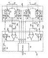
- control circuit 45 An example of a control circuit 45 is illustrated in Figure 4 wherein four pairs of transistors 50, 51; 52, 53; 54, 55; and 56, 57 have their bases connected to logic signals Fl, F2, F3, F4, F5, F6, F7 and F8, and acts as switches to cause the current to flow selectively in the windings A, A, B and B.
- the signals Fl to F8 are the outputs of a series of AND-gates 58 and inverters 59 which have as their inputs signals FA, FB, FC and FD supplied by a decoder circuit 46 on the basis of the data that the latter receives from the controlling unit 13 on a channel 47 (see Figures 1 and 4) and signals INl and IN2 which are supplied by two flip-flops 48 and 49 respectively.
- the circuit 46 is of known type and is therefore not described in detail herein.
- the circuit 45 further comprises an oscillator 60 which supplies timing pulses OS at a constant frequency, for example 22 kHz.
- the two flip-flops 48 and 49 are set by the signal OS and reset by signals RESi and RES2 respectively which are outputted by two comparators Cl and C2.
- An input of each comparator Cl and C2 is connected to a reference signal V REF while applied to another input thereof is a signal which is taken off at one end of a sensing resistor RS 1 and RS 2 respectively.
- a voltage divider Disposed between the resistors RS 1 and the comparator Cl is a voltage divider comprising two resistors R14 and R16; similarly, disposed between the resistor RS 2 and the comparator C2 are two resistors R13 and R15.
- the mode of operation of the circuit 45 is as follows:
- the frequency at which the circuit 46 generates the signals FA, FB, FC and FD may vary in dependence on the angular distance that the rotor is to cover in order to reach the desired position. That is well known in the art and can be achieved by means of programs which are recorded in a memory of the unit 13. The time for covering that distance is minimised but the rotor does not stop at around the desired position but will tend to-oscillate, thus delaying the moment at which the element controlled thereby may be used.
- control circuit 10 (see Figure 1) according to the invention will now be described in detail, which circuit makes it possible to damp the oscillations of the rotor after the rotor has been moved into the desired angular position.
- the danping circuit 14 is connected to one of the windings of the stepping motor 10 in such a way as to pick off an electrical signal which is representative of the speed of the rotor. That information is processed and used to affect the power supply to the other windings, as will be described in greater detail hereinafter.
- Figure 5 illustrates a stepping motor of single-pole type, similar to that shown in Figure 2, in which however the windings A and A are connected together in anti-parallel and the ends 70 and 71 thereof are connected to two three-way switches 72 and 73 and the winding B has the ends thereof connected to two switches 74 and 75.
- the winding B is not connected to the power supply VA but has one end 76 connected to earth and one end 77 connected to the damping circuit 14.
- the motor 11 while being of single-pole type, has the windings thereof connected in such a way as accordingly to constitute in fact a bipolar type of motor.
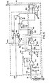
- the damping circuit 14 (see Figure 6) comprises four blocks 80, 81, 82 and 83: the blocks 80 and 83 are filter and gain regulator means, the block 81 is merely an inverting block and the block 82 is a logic block for dealing with a signal ATT from the unit 13 and a signal POS from the circuit 46.
- the block 80 comprises an amplifier 85 having a first input to which the voltage signal that is proportional to the back EMF (electromotive force)taken off the winding B is applied by way of two resistors R2 and R3 and a capacitor Cll.
- the other input of the amplifier 85 is connected to earth by way of a resistor R4.
- Disposed between the output of the amplifier 85 and its first input are a capacitor C12 and a resistor Rl.
- the block 80 further comprises a resistor R12 and a capacitor C13.
- the block 81 comprises an amplifier 86 which has a first input connected to the output of the block 80 by way of a resistor R6 and a second input connected to earth by means of a resistor R7.
- a resistor R5 is disposed between the output of the amplifier 86 and its first input.
- the logic circuit 82 comprises two NAND-gates 87 and 88 each having an input connected to the signal ATT from the unit 13 (see Figure 1).
- the gate 87 (see Figure 6) has its other input connected to the signal POS from the circuit 46 while the gate 88 has its other input connected to the output of an inverter 89, to the input of which is applied the signal POS.
- the block 82 further comprises two field effect transistors (FET) 90 and 91 having their control electrodes connected to the outputs of the gates 87 and 88 respectively.
- the input of the FET 90 is connected to the output of the block 80 by means of a resistor R9 while the input of the FET 91 is connected to the output of the block 81 by means of a resistor R8.
- the block 83 comprises the two resistors R8 and R9 and an amplifier 93 which has a first input connected to the outputs of the FETs 90 and 91 and another input connected to earth by means of a resistor Rll.
- a capacitor C14 and a resistor R10 are disposed between the output of the amplifier 93 and its first input.
- the output SMR of the damping circuit 14 is applied to the control circuit 12 (see Figures 1 and 7).
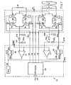
- the control circuit 12 is similar to the above-described circuit 45 (Fig 4).in that the latter, as has been seen, is capable of controlling a bipolar stepping motor.
- the difference between the circuit 45 and the circuit 12 is that one end of the resistor R13, which is associated with the sensing resistor RS 2 , is connected to the output SMR of the circuit 14. Accordingly the circuit 14 which reconstitutes the back EMF present in the winding B of the motor 11 and obtains therefrom speed information then modulates the current of the windings A and A to achieve the desired damping effect.
- the winding B which in this embodiment is not used for directly causing the rotary movement of the rotor. It should be considered therefore that, after having given the last advance movement order to the motor, the current is no longer varied in the winding B and that terms deriving from the possible variation in that current are consequently not present at the ends of the winding B. Therefore, during the damping phase, the signal which is taken from the winding B contains only two terms: the square wave component at the-frequency of the pulses OS and the back EMF.
- the square wave component is present because, as described above, the current in the windings A-A and B are regulated in a switching mode, that is to say, by closing and opening the power supply means at the frequency of the pulses OS.
- the component at a frequency of 22 kHz at the ends of the winding B is of a value between peaks which is approximately equal to the value of the power supply voltage VA ( Figure 9).
- the block 80 of the circuit 14, by means of the three filters formed by the components R2, R3 and Cll; R1 and C12; R12 and C13, filters the 22 kHz component of the signal of the winding B and, by means of the amplifier 85, amplifies the back EMF component.
- the output signal Sx of the block 80 is of the form shown in Figure 9 and, although inverted, it will be seen that it is proportional to the signal Vx of effective angular speed of the motor shaft with respect to the nominal stopped speed, while also having a small residual 22 kHz component.
- Each filter attenuates the 22 kHz component by a factor of about 10 and thus, at the output of the block 80, the value of that component is equal to a thousandth of the product of the power supply voltage VA by the gain coefficient of the amplifier 85.
- the speed of the rotor 20 is considered to be positive when it is moving towards the pole piece 16 and negative when it is moving towards the pole piece 17.
- the winding B is wound on the pole pieces 17 and 19 in such a way as to generate by induction a voltage which is positive when the rotor is moving with its pole N towards the pole piece 16 and conversely negative when the rotor 20 is moving towards the pole piece 17. That induced signal is applied, being filtered and amplified by the circuit 14, to the circuit 12 in such a way that it modulates the current I A, A in the windings A and A.
- the current I A, A will be of the form shown in Figure 9: it will be higher than the nominal current I n when the. rotor 20 is moving towards the pole piece 17 and lower than the nominal current In when the rotor 20 is moving towards the pole piece 16.
- the rotor 20 When however the rotor 20 is stationary with its pole N disposed between the pole pieces 18 and 19, the currents in the windings A, A and B are inverted. In order to damp the oscillations of the rotor 20 with respect to its nominal position, it is necessary in this new condition also to invert the modulation of the current I A, A in the windings A, A . In order to achieve that result, use is made of the signal POS in respect of position of the rotor 20, which is generated by the decoder circuit 46. The signal POS is at logic level 1 when the rotor 20 has its pole N between the pole pieces 16 and 17 and at level 0 in the other cases.
- the unit 13 When the unit 13 applies to the circuit 12 the last step command to be performed, it also sets at logic level 1 the signal ATT for activation of the circuit 14, which is normally deactivated, the signal ATT being at logic level O.
- the output signal Sx of the block 80 (see Figure 6) is applied by way of the block 89 and the resistor R8 to the amplifier 93 of the block 83.
- the block 81 being a simple inverting amplifier with unit gain, the signal Sx is inverted once by the block 81 and then again by the block 83 whereby the signal SMR which comes out of the circuit 14 is amplified but in phase with the signal Sx.
- the capacitor C14 performs the function of a further rejection filter for the 22 kHz component.
- the signal SMR is applied to the control circuit 12 (see Figure 7).
- the peak of the current I A, A which flows in the windings A and A is equal to the ratio between VS 2 and RS 2 , by virtue of the ratio between the sum of Rl3 and R15, and R13. Since the voltage VS 2 tends continuously to go to the value V REF , the peak of the current I A, A may be considered as equal to the ratio between V REF and RS 2 , by virtue of the ratio between the sum of Rl3 and R15, and Rl3.
- a damping circuit is connected to one of the windings of the motor to take off an electrical signal which is representative of the angular speed of the rotor and is capable of consequentially influencing the power supply of the other windings to damp the oscilaltions of the rotor during the stopping thereof in a given angular position.
- Other embodiments are also possible.
- a circuit according to the invention has been used for controlling a stepping motor used for angular positioning of a character carrying disc (daisy wheel) of an office printer and has given surprising results. By eliminating the oscillations of the rotor the circuit has reduced by almost half the total time of each selection cycle, making the printer much faster.
Landscapes
- Engineering & Computer Science (AREA)
- Power Engineering (AREA)
- Control Of Stepping Motors (AREA)
Abstract
Description
- The present invention relates to an electronic circuit ' for the control of a stepping motor having a rotor and a plurality of selectively energisable windings, comprising power supply means connected to the windings to cause rotary movement of the rotor towards a desired angular position.
- One of the adverse intrinsic aspects of stepping motors, particularly when they are controlled in a non-servo manner, that is to say, without theassistance of transducers which are connected to the rotor, is the problem of oscillations of the rotor with respect to the nominal stopped position, which oscillations substantially affect the total time of an angular advance cycle. This phenomenon is very important particularly when the motor is used as a member for positioning elements which are continously to change their position, for example the character carrying discs of flexible blade type (daisy wheels) which are used in high-speed typing and printing machines, or the magnetic heads which write and read data on magnetic carriers.
- One of the known arrangements which are used for damping the oscillations of the rotor of a stepping motor utilizes a metal ring keyed on the motor shaft, in such a way that the metal ring can rotate together with the shaft. The ring is rotatable within a cavity which is filled with lubricating oil and received in a cylindrical container which is held stationary.
- That mechanical damping action only partially eliminates the oscillatory movements of the rotor, and also suffers from the disadvantage of substantially increasing the mass associated with the rotor, which thereby has an adverse effect on the efficiency of the motor.
- The object of the present invention is to damp the oscillations of the rotor of a stepping motor, using an electronic circuit associated with the circuit for pilot control of the motor.
- In accordance with that aim, and for eliminating the disadvantages of mechanical damping arrangements, the circuit according to the invention is characterised in that a damping circuit is connected to one of the windings to pick off an electrical signal representative of the angular speed of the rotor and is connected to the power supply means to modify the power supply to the other windings in such a way as to damp the oscillations of the rotor during stopping thereof in the desired angular position.
- The invention will be described in more detail, by way of example, with reference to the accompanying drawings, in which:
- Figure 1 is a block circuit diagram of a control circuit embodying the invention,
- Figure 2 is a diagrammatic view of a stepping motor of single-pole type,
- Figure 3 is a diagrammatic view of a stepping motor of bipolar type,
- Figure 4 is an electrical diagram of a control circuit of a stepping motor of bipolar type,
- Figure 5 is a diagrammatic view of a stepping motor which can be controlled by a circuit according to the invention,
- Figure 6 is a detail view of a first part of a circuit embodying the invention,
- Figure 7 is a detail view of a second part of the circuit,
- Figure 8 is a diagram showing some signals in the circuits shown in Figure 4 and Figure 7, and
- Figure 9 is a group of diagrams showing some signals in the circuit of Figure 6.
- Referring to Figure 1, an
electronic circuit 10 embodying the invention for control of astepping motor 11 comprises acontrol circuit 12 which, on the basis of the data supplied thereto by a controllingunit 13 which is formed for example by a microprocessor, is capable of generating control pulses for the windings of themotor 11, as will be seen in greater detail hereinafter. Adamping circuit 14 is connected to themotor 11, to the controllingunit 13 and to thecontrol circuit 12. - Before going into a detailed description of the
damping circuit 14 and the effective connection thereof to the other parts of thecircuit 10, some considerations relating to stepping motors in general will be set out. - Figure 2 shows the equivalent diagram of a stepping motor of single-pole, four-phase type, which comprises a
stator 15 provided with pole pieces ofshoes rotor 20 formed by a permanent magnet is mounted on ashaft 21 which is coaxial with respect to thestator 15. The windings A, A, B and B have one end connected to the power supply VA By way of on-offswitches rotor 20 stationary, the switch corresponding to the winding associated with the position which therotor 20 is desired to assume is closed. For example, to hold therotor 20 between thepole pieces switch 22 is closed and the winding A is energised to make thepole pieces 16 and 18 S and N poles respectively. - In order to rotate the
rotor 20 with respect to thestator 15, the other windings are progressively energised: by closing theswitch 24 and opening theswitch 22, only the winding B is energised and therotor 20 rotates by one step in a clockwise direction, moving into the position shown at 20' in dash-dotted lines in figure 2. If however the windings A and B are energised simultaneously, therotor 20 takes up aposition 20" which is intermediate between thepole pieces rotor 20 is held stationary by a force which is the resultant of the two forces generated by the magnetic fields in thepole pieces rotor 20 is disposed precisely opposite one of the pole pieces of thestator 15. As will be seen, in single-pole stepping motors, the current always flow in the same direction in the windings. - Figure 3 however shows the equivalent diagram of a bipolar stepping motor comprising a
stator 31 provided withradial pole pieces rotor 36 comprising a permanent magnet is mounted on ashaft 37. - The windings A and A are connected in series with each other and have one end connected to a
switch 41 and the other end connected to aswitch 42. The windigns B and B are in turn connected in series and have one end connected to a switch 43-and another end connected to aswitch 44. Theswitches - In the condition shown in Figure 3, the
switches switch 41 is connected to earth and theswitch 42 is connected to the power supply VA, whereby the current flows in the windings A and Ã, holding therotor 36 stationary with the pole N in front of thepole piece 32. - To rotate the
rotor 36 in the clockwise direction by half a step (position 36"), 'theswitch 43 is moved into position a and theswitch 44 is moved into position c in such a way that current also flows in the windings B and B. - Both types of motor, the single-pole and the bipolar type, may be controlled in such a way that the rotor performs half a stepping motion at a time, or a complete step at a time.
- As regards controlling stepping motors, one of the most widely used modes of control is that which involves a constant current with intermittent function, or the "chopper" mode. The constant-current supply mode is used in order to be able to provide a torque which is virtually independent of speed, within a certain range of values, while the adoption of a chopper mode of operation, rather than a linear mode, makes it possible to provide a high ratio between useful output and power supplied. An example of a
control circuit 45 is illustrated in Figure 4 wherein four pairs oftransistors - The signals Fl to F8 are the outputs of a series of AND-
gates 58 andinverters 59 which have as their inputs signals FA, FB, FC and FD supplied by adecoder circuit 46 on the basis of the data that the latter receives from the controllingunit 13 on a channel 47 (see Figures 1 and 4) and signals INl and IN2 which are supplied by two flip-flops circuit 46 is of known type and is therefore not described in detail herein. - The
circuit 45 further comprises anoscillator 60 which supplies timing pulses OS at a constant frequency, for example 22 kHz. The two flip-flops - Disposed between the resistors RS1 and the comparator Cl is a voltage divider comprising two resistors R14 and R16; similarly, disposed between the resistor RS2 and the comparator C2 are two resistors R13 and R15.
- The mode of operation of the
circuit 45 is as follows: - It is assumed that the signal FA is at
logic level 1 and that the signal FB is at logic level O; that means that thetransistors transistors transistors flop 48 and sets to level O the inhibition signal INl which disconnects the power supply from the windings B and B. The signal IN1 remains at level O until a fresh pulse OS (see Figure 8) is generated by the oscillator 60 (see Figure 4). When the signal IN1 goes tolevel 1, the initial power supply conditions are re-established; that being until the signal FA remains atlevel 1. A similar mode of operation is found in the circuit portion which controls the windings A and A by means of the signals FC and FD. - It is clear that the frequency at which the
circuit 46 generates the signals FA, FB, FC and FD may vary in dependence on the angular distance that the rotor is to cover in order to reach the desired position. That is well known in the art and can be achieved by means of programs which are recorded in a memory of theunit 13. The time for covering that distance is minimised but the rotor does not stop at around the desired position but will tend to-oscillate, thus delaying the moment at which the element controlled thereby may be used. - After those general considerations, the control circuit 10 (see Figure 1) according to the invention will now be described in detail, which circuit makes it possible to damp the oscillations of the rotor after the rotor has been moved into the desired angular position.
- In accordance with the invention, the
danping circuit 14 is connected to one of the windings of the steppingmotor 10 in such a way as to pick off an electrical signal which is representative of the speed of the rotor. That information is processed and used to affect the power supply to the other windings, as will be described in greater detail hereinafter. - As an example and in order to arrive at a better understanding of this feature of the invention, Figure 5 illustrates a stepping motor of single-pole type, similar to that shown in Figure 2, in which however the windings A and A are connected together in anti-parallel and the
ends way switches 72 and 73 and the winding B has the ends thereof connected to twoswitches end 76 connected to earth and oneend 77 connected to thedamping circuit 14. - In that way, the
motor 11, while being of single-pole type, has the windings thereof connected in such a way as accordingly to constitute in fact a bipolar type of motor. - The damping circuit 14 (see Figure 6) comprises four
blocks blocks block 81 is merely an inverting block and the block 82 is a logic block for dealing with a signal ATT from theunit 13 and a signal POS from thecircuit 46. In particular, theblock 80 comprises an amplifier 85 having a first input to which the voltage signal that is proportional to the back EMF (electromotive force)taken off the winding B is applied by way of two resistors R2 and R3 and a capacitor Cll. The other input of the amplifier 85 is connected to earth by way of a resistor R4. Disposed between the output of the amplifier 85 and its first input are a capacitor C12 and a resistor Rl. Theblock 80 further comprises a resistor R12 and a capacitor C13. - The
block 81 comprises anamplifier 86 which has a first input connected to the output of theblock 80 by way of a resistor R6 and a second input connected to earth by means of a resistor R7. A resistor R5 is disposed between the output of theamplifier 86 and its first input. - The logic circuit 82 comprises two NAND-
gates circuit 46 while thegate 88 has its other input connected to the output of aninverter 89, to the input of which is applied the signal POS. The block 82 further comprises two field effect transistors (FET) 90 and 91 having their control electrodes connected to the outputs of thegates FET 90 is connected to the output of theblock 80 by means of a resistor R9 while the input of theFET 91 is connected to the output of theblock 81 by means of a resistor R8. - The
block 83 comprises the two resistors R8 and R9 and anamplifier 93 which has a first input connected to the outputs of theFETs amplifier 93 and its first input. The output SMR of the dampingcircuit 14 is applied to the control circuit 12 (see Figures 1 and 7). - The
control circuit 12 is similar to the above-described circuit 45 (Fig 4).in that the latter, as has been seen, is capable of controlling a bipolar stepping motor. The difference between thecircuit 45 and thecircuit 12 is that one end of the resistor R13, which is associated with the sensing resistor RS2, is connected to the output SMR of thecircuit 14. Accordingly thecircuit 14 which reconstitutes the back EMF present in the winding B of themotor 11 and obtains therefrom speed information then modulates the current of the windings A and A to achieve the desired damping effect. - Other components, in addition to the back EMF signal, which is that which is to be isolated, are therefore present in the winding B which in this embodiment is not used for directly causing the rotary movement of the rotor. It should be considered therefore that, after having given the last advance movement order to the motor, the current is no longer varied in the winding B and that terms deriving from the possible variation in that current are consequently not present at the ends of the winding B. Therefore, during the damping phase, the signal which is taken from the winding B contains only two terms: the square wave component at the-frequency of the pulses OS and the back EMF. The square wave component is present because, as described above, the current in the windings A-A and B are regulated in a switching mode, that is to say, by closing and opening the power supply means at the frequency of the pulses OS. The component at a frequency of 22 kHz at the ends of the winding B is of a value between peaks which is approximately equal to the value of the power supply voltage VA (Figure 9).
- The
block 80 of thecircuit 14, by means of the three filters formed by the components R2, R3 and Cll; R1 and C12; R12 and C13, filters the 22 kHz component of the signal of the winding B and, by means of the amplifier 85, amplifies the back EMF component. The output signal Sx of theblock 80 is of the form shown in Figure 9 and, although inverted, it will be seen that it is proportional to the signal Vx of effective angular speed of the motor shaft with respect to the nominal stopped speed, while also having a small residual 22 kHz component. Each filter attenuates the 22 kHz component by a factor of about 10 and thus, at the output of theblock 80, the value of that component is equal to a thousandth of the product of the power supply voltage VA by the gain coefficient of the amplifier 85. - The way in which the signal representative of the angular speed of the
rotor 20 is used to damp the oscillations of therotor 20 with respect to the nominal stopped position thereof will now be described. - It is assumed that the
rotor 20 is to be stopped in the position shown in Figure 5 with the pole N in an intermediate position between thepole pieces - Observing the signal Vx (see Figure 9), the speed of the
rotor 20 is considered to be positive when it is moving towards thepole piece 16 and negative when it is moving towards thepole piece 17. - The winding B is wound on the
pole pieces pole piece 16 and conversely negative when therotor 20 is moving towards thepole piece 17. That induced signal is applied, being filtered and amplified by thecircuit 14, to thecircuit 12 in such a way that it modulates the current IA,A in the windings A and A. In particular, the current IA,A will be of the form shown in Figure 9: it will be higher than the nominal current In when the.rotor 20 is moving towards thepole piece 17 and lower than the nominal current In when therotor 20 is moving towards thepole piece 16. - When however the
rotor 20 is stationary with its pole N disposed between thepole pieces rotor 20 with respect to its nominal position, it is necessary in this new condition also to invert the modulation of the current IA,A in the windings A,A . In order to achieve that result, use is made of the signal POS in respect of position of therotor 20, which is generated by thedecoder circuit 46. The signal POS is atlogic level 1 when therotor 20 has its pole N between thepole pieces level 0 in the other cases. - When the
unit 13 applies to thecircuit 12 the last step command to be performed, it also sets atlogic level 1 the signal ATT for activation of thecircuit 14, which is normally deactivated, the signal ATT being at logic level O. - With the signal ATT at logic level 1 (see Figure 6), if the signal POS is also at
logic level 1, theFET 90 is closed and theFET 91 is opened, while if the signal POS is atlogic level 0, theFET 90 is opened and theFET 91 is closed. - Therefore, when the
rotor 20 is stationary in the position shown in Figure 5, the signal Sx which is outputted by the block 80 (see Figure 6) is applied by way of the resistor R9 to theamplifier 93 of theblock 83. The output signal SMR of thecircuit 14 is inverted and amplified with respect to the signal Sx (see Figure 9). - When however the rotor 20 (see Figure 5) is stopped with its pole N between the
pole pieces block 89 and the resistor R8 to theamplifier 93 of theblock 83. With theblock 81 being a simple inverting amplifier with unit gain, the signal Sx is inverted once by theblock 81 and then again by theblock 83 whereby the signal SMR which comes out of thecircuit 14 is amplified but in phase with the signal Sx. - In both cases, the capacitor C14 performs the function of a further rejection filter for the 22 kHz component. As already noted above, the signal SMR is applied to the control circuit 12 (see Figure 7).
- The peak of the current IA,
A which flows in the windings A and A is equal to the ratio between VS2 and RS2, by virtue of the ratio between the sum of Rl3 and R15, and R13. Since the voltage VS2 tends continuously to go to the value VREF, the peak of the current IA,A may be considered as equal to the ratio between VREF and RS2, by virtue of the ratio between the sum of Rl3 and R15, and Rl3. - When the signal SMR is at zero, the current flowing in the windings A, A is the nominal current I ; when however the signal SMR assumes positive or negative'values, that causes a reduction or an increase respectively in the current IA,
A which flows in the windings, modulating same with respect to its nominal value I . That is because the voltage at RS2, added to that of the signal SMR, must be maintained equal to VS2 and thus to VREF. - That gives rapid damping of the
rotor 20. - It will be clear from the description herein that a damping circuit is connected to one of the windings of the motor to take off an electrical signal which is representative of the angular speed of the rotor and is capable of consequentially influencing the power supply of the other windings to damp the oscilaltions of the rotor during the stopping thereof in a given angular position. Other embodiments are also possible.
- A circuit according to the invention has been used for controlling a stepping motor used for angular positioning of a character carrying disc (daisy wheel) of an office printer and has given surprising results. By eliminating the oscillations of the rotor the circuit has reduced by almost half the total time of each selection cycle, making the printer much faster.
Claims (8)
Applications Claiming Priority (2)
| Application Number | Priority Date | Filing Date | Title |
|---|---|---|---|
| IT6767383 | 1983-06-17 | ||
| IT67673/83A IT1159416B (en) | 1983-06-17 | 1983-06-17 | ELECTRONIC CIRCUIT FOR PILOTING A STEPPING MOTOR |
Publications (4)
| Publication Number | Publication Date |
|---|---|
| EP0129377A2 true EP0129377A2 (en) | 1984-12-27 |
| EP0129377A3 EP0129377A3 (en) | 1985-12-18 |
| EP0129377B1 EP0129377B1 (en) | 1989-03-15 |
| EP0129377B2 EP0129377B2 (en) | 1992-07-08 |
Family
ID=11304393
Family Applications (1)
| Application Number | Title | Priority Date | Filing Date |
|---|---|---|---|
| EP84303882A Expired EP0129377B2 (en) | 1983-06-17 | 1984-06-08 | Stepping motor control circuit |
Country Status (4)
| Country | Link |
|---|---|
| US (1) | US4580087A (en) |
| EP (1) | EP0129377B2 (en) |
| DE (1) | DE3477326D1 (en) |
| IT (1) | IT1159416B (en) |
Cited By (1)
| Publication number | Priority date | Publication date | Assignee | Title |
|---|---|---|---|---|
| EP0569191A2 (en) * | 1992-05-04 | 1993-11-10 | Hughes Aircraft Company | Mixed mode stepper motor controller and method |
Families Citing this family (3)
| Publication number | Priority date | Publication date | Assignee | Title |
|---|---|---|---|---|
| ATE53720T1 (en) * | 1982-09-28 | 1990-06-15 | Yang Tai Her | STEPPER MOTOR. |
| US6586898B2 (en) | 2001-05-01 | 2003-07-01 | Magnon Engineering, Inc. | Systems and methods of electric motor control |
| TWI532298B (en) * | 2014-06-25 | 2016-05-01 | Hsu Fu Tzu | Switching magnetoresistive motor, magnetoresistive motor drive circuit and magnetoresistive motor |
Citations (2)
| Publication number | Priority date | Publication date | Assignee | Title |
|---|---|---|---|---|
| US3588661A (en) * | 1968-04-24 | 1971-06-28 | Mesur Matic Electronics Corp | Electronic damping for stepping motors |
| DE2447673A1 (en) * | 1974-10-05 | 1976-04-08 | Ibm Deutschland | PROCEDURE AND ARRANGEMENT FOR STEPPER MOTOR CONTROL |
Family Cites Families (2)
| Publication number | Priority date | Publication date | Assignee | Title |
|---|---|---|---|---|
| US3727121A (en) * | 1971-04-08 | 1973-04-10 | Gerber Scientific Instr Co | Step motor damping method and apparatus |
| US4286202A (en) * | 1979-07-16 | 1981-08-25 | International Business Machines Corp. | Electronic damping of stepper motor |
-
1983
- 1983-06-17 IT IT67673/83A patent/IT1159416B/en active
-
1984
- 1984-06-08 DE DE8484303882T patent/DE3477326D1/en not_active Expired
- 1984-06-08 EP EP84303882A patent/EP0129377B2/en not_active Expired
- 1984-06-18 US US06/621,475 patent/US4580087A/en not_active Expired - Fee Related
Patent Citations (2)
| Publication number | Priority date | Publication date | Assignee | Title |
|---|---|---|---|---|
| US3588661A (en) * | 1968-04-24 | 1971-06-28 | Mesur Matic Electronics Corp | Electronic damping for stepping motors |
| DE2447673A1 (en) * | 1974-10-05 | 1976-04-08 | Ibm Deutschland | PROCEDURE AND ARRANGEMENT FOR STEPPER MOTOR CONTROL |
Cited By (2)
| Publication number | Priority date | Publication date | Assignee | Title |
|---|---|---|---|---|
| EP0569191A2 (en) * | 1992-05-04 | 1993-11-10 | Hughes Aircraft Company | Mixed mode stepper motor controller and method |
| EP0569191A3 (en) * | 1992-05-04 | 1994-05-04 | Hughes Aircraft Co |
Also Published As
| Publication number | Publication date |
|---|---|
| IT8367673A0 (en) | 1983-06-17 |
| DE3477326D1 (en) | 1989-04-20 |
| EP0129377B2 (en) | 1992-07-08 |
| EP0129377B1 (en) | 1989-03-15 |
| IT1159416B (en) | 1987-02-25 |
| EP0129377A3 (en) | 1985-12-18 |
| US4580087A (en) | 1986-04-01 |
Similar Documents
| Publication | Publication Date | Title |
|---|---|---|
| CA1155911A (en) | Electronic damping of stepper motor | |
| US3906320A (en) | Control of brushless D-C motors | |
| US5489831A (en) | Pulse width modulating motor controller | |
| US4631459A (en) | Brushless DC motor | |
| US5382890A (en) | Integrated circuit driver having current limiter for brushless motor | |
| EP0123807A2 (en) | Driving and detection of back EMF in permanent magnet step motors | |
| JPS6126315B2 (en) | ||
| US4306181A (en) | Drive circuitry for electric motor | |
| JPH0728553B2 (en) | Motor drive circuit | |
| EP0108732B1 (en) | A device for controlling a reluctance motor | |
| US4100471A (en) | Stepping motor control circuit | |
| US4242623A (en) | Miniature electric stepping motor | |
| US4580087A (en) | Stepping motor control circuit | |
| KR20010083776A (en) | Device for driving a multi-phase d.c. motor | |
| US3959700A (en) | Speed control device for transistor motor | |
| US4158795A (en) | Brushless DC motors | |
| US4415845A (en) | Electric motor control device | |
| US3569808A (en) | Servo system for magnetic recording and reproducing apparatus | |
| JP2529674B2 (en) | DC motor | |
| US4386298A (en) | Brushless dc motor control circuit | |
| JP2667216B2 (en) | Drive circuit for brushless motor | |
| JPH11353835A (en) | Head return circuit with hold function | |
| SU974534A1 (en) | Registering device servo drive | |
| JPS582558B2 (en) | Electronic damper for pulse motor | |
| JPH0216673B2 (en) |
Legal Events
| Date | Code | Title | Description |
|---|---|---|---|
| PUAI | Public reference made under article 153(3) epc to a published international application that has entered the european phase |
Free format text: ORIGINAL CODE: 0009012 |
|
| AK | Designated contracting states |
Designated state(s): DE FR GB |
|
| PUAL | Search report despatched |
Free format text: ORIGINAL CODE: 0009013 |
|
| AK | Designated contracting states |
Designated state(s): DE FR GB |
|
| 17P | Request for examination filed |
Effective date: 19860609 |
|
| 17Q | First examination report despatched |
Effective date: 19870722 |
|
| GRAA | (expected) grant |
Free format text: ORIGINAL CODE: 0009210 |
|
| AK | Designated contracting states |
Kind code of ref document: B1 Designated state(s): DE FR GB |
|
| REF | Corresponds to: |
Ref document number: 3477326 Country of ref document: DE Date of ref document: 19890420 |
|
| ET | Fr: translation filed | ||
| PLBI | Opposition filed |
Free format text: ORIGINAL CODE: 0009260 |
|
| 26 | Opposition filed |
Opponent name: N.V. PHILIPS' GLOEILAMPENFABRIEKEN Effective date: 19891214 |
|
| PUAH | Patent maintained in amended form |
Free format text: ORIGINAL CODE: 0009272 |
|
| STAA | Information on the status of an ep patent application or granted ep patent |
Free format text: STATUS: PATENT MAINTAINED AS AMENDED |
|
| 27A | Patent maintained in amended form |
Effective date: 19920708 |
|
| AK | Designated contracting states |
Kind code of ref document: B2 Designated state(s): DE FR GB |
|
| ET3 | Fr: translation filed ** decision concerning opposition | ||
| PGFP | Annual fee paid to national office [announced via postgrant information from national office to epo] |
Ref country code: GB Payment date: 19930528 Year of fee payment: 10 |
|
| PGFP | Annual fee paid to national office [announced via postgrant information from national office to epo] |
Ref country code: FR Payment date: 19930609 Year of fee payment: 10 |
|
| PGFP | Annual fee paid to national office [announced via postgrant information from national office to epo] |
Ref country code: DE Payment date: 19930623 Year of fee payment: 10 |
|
| PG25 | Lapsed in a contracting state [announced via postgrant information from national office to epo] |
Ref country code: GB Effective date: 19940608 |
|
| GBPC | Gb: european patent ceased through non-payment of renewal fee |
Effective date: 19940608 |
|
| PG25 | Lapsed in a contracting state [announced via postgrant information from national office to epo] |
Ref country code: FR Effective date: 19950228 |
|
| PG25 | Lapsed in a contracting state [announced via postgrant information from national office to epo] |
Ref country code: DE Effective date: 19950301 |
|
| REG | Reference to a national code |
Ref country code: FR Ref legal event code: ST |