EP0129325A2 - Track lighting - Google Patents
Track lighting Download PDFInfo
- Publication number
- EP0129325A2 EP0129325A2 EP84303291A EP84303291A EP0129325A2 EP 0129325 A2 EP0129325 A2 EP 0129325A2 EP 84303291 A EP84303291 A EP 84303291A EP 84303291 A EP84303291 A EP 84303291A EP 0129325 A2 EP0129325 A2 EP 0129325A2
- Authority
- EP
- European Patent Office
- Prior art keywords
- contacts
- low voltage
- track
- fitting
- rails
- Prior art date
- Legal status (The legal status is an assumption and is not a legal conclusion. Google has not performed a legal analysis and makes no representation as to the accuracy of the status listed.)
- Withdrawn
Links
Images


Classifications
-
- H—ELECTRICITY
- H01—ELECTRIC ELEMENTS
- H01R—ELECTRICALLY-CONDUCTIVE CONNECTIONS; STRUCTURAL ASSOCIATIONS OF A PLURALITY OF MUTUALLY-INSULATED ELECTRICAL CONNECTING ELEMENTS; COUPLING DEVICES; CURRENT COLLECTORS
- H01R25/00—Coupling parts adapted for simultaneous co-operation with two or more identical counterparts, e.g. for distributing energy to two or more circuits
- H01R25/14—Rails or bus-bars constructed so that the counterparts can be connected thereto at any point along their length
- H01R25/147—Low voltage devices, i.e. safe to touch live conductors
-
- F—MECHANICAL ENGINEERING; LIGHTING; HEATING; WEAPONS; BLASTING
- F21—LIGHTING
- F21V—FUNCTIONAL FEATURES OR DETAILS OF LIGHTING DEVICES OR SYSTEMS THEREOF; STRUCTURAL COMBINATIONS OF LIGHTING DEVICES WITH OTHER ARTICLES, NOT OTHERWISE PROVIDED FOR
- F21V21/00—Supporting, suspending, or attaching arrangements for lighting devices; Hand grips
- F21V21/34—Supporting elements displaceable along a guiding element
- F21V21/35—Supporting elements displaceable along a guiding element with direct electrical contact between the supporting element and electric conductors running along the guiding element
-
- H—ELECTRICITY
- H01—ELECTRIC ELEMENTS
- H01R—ELECTRICALLY-CONDUCTIVE CONNECTIONS; STRUCTURAL ASSOCIATIONS OF A PLURALITY OF MUTUALLY-INSULATED ELECTRICAL CONNECTING ELEMENTS; COUPLING DEVICES; CURRENT COLLECTORS
- H01R2201/00—Connectors or connections adapted for particular applications
- H01R2201/08—Connectors or connections adapted for particular applications for halogen lamps
Definitions
- the present invention relates to a track lighting system.
- track lighting means in the context of a track lighting system an electric lighting system in which a lamp fitting is engageable at a randomly selected position along a track having conductor rails which each have an exposed surface contactable by a respective contact in the lamp fitting.
- argon filled lamps are generally used with conventional track lighting systems.
- halogen-filled, quartz-bulb lamps as have found increasing use in vehicle headlights, operate at a much higher colour temperature and thus, by more efficient conversion of electricity to light, provide an opportunity for the provision of more efficient, cheaper lighting.
- a low voltage track lighting system comprising:
- low voltage means 30 volts or less.
- a low voltage track lighting track comprising an elongate body of insulating material and a pair of elongate conductor rails supported on the body, the arrangement and shape of the body and the conductor rails being such that in use, with a lamp fitting having a pair of contacts urgable into good electric contact with their respective rails, each conductor rail is compressed by its contact against the portion of the body supporting it and the supporting portion is adapted to be pressed against on its side opposite from the said conductor rail by force resulting from the lamp fitting to provide that contact pressure between the rail and its contact can provide good electric contact therebetween
- a low voltage track-lighting track comprising an extrusion of insulating material and a pair of conductor rails accommodated on the extrusion, the conductor rails presenting a shape which may be complementarily matched by contacts of a lamp fitting.
- the conductor rails present flat faces, although the track may be bent to convenient installed shape.
- the conductor rails are positioned on either side of a central web of the extrusion.
- conductor rails may be protected by a pair of flanges extending in the manner a channel on either side, but spaced from the central web and conductor rails, such flanges are not necessary because the conductor rails do not have to be protected for safety reasons due to the use of low voltage.
- the conductor rails may be stiff enough to be self-supporting if located at their edges, the sandwich arrangement of one conductor rail, central web, other conductor rail preferably provides that the arrangement is self-supporting against force exerted by lamp-fitting contacts tending to squeeze the sandwich arrangement.
- the extrusion includes conductor rail locating grooves.
- the extrusion may be adapted for support on a ceiling or wall on its own, for instance by having a broad flange forming the head of a T - in section - with the central web forming the leg of the T, the flange being broad enough to accommodate fixing screw holes or a strip of self-adhesive material on its upper surface; it is preferred that the extrusion be shaped for clip attachment. Clips for such attachment may be short, along the length of the extrusion, but again it is preferred that the "clips" be in the form of a separate plastics material extrusion.
- This second extrusion may be initially attached in position, by nail, screw, double-sided self-adhesive tape or the like and the conductor carrying extrusion subsequently snapped or manipulated into position.
- Such two extrusion track has the advantage that it can be narrow, hence cheap and neat.
- a low voltage track-lighting lamp fitting including a pair of conductor-rail-engaging contacts which shaped complementarily to the rails and which are adapted and arranged to be moved for contact with conductor rails.
- the track may be channel shaped with conductor rails on either side of the channel, in which case the contacts are arranged to be moved away from each other.
- the track may have the two conductor rails on the same side of a web of the track extrusion in which case the contacts are arranged to be moved in the same direction.
- the contacts are arranged to be moved in towards each other.
- the contacts may be spring biassed for movement in towards each other, with the fitting including means for moving the contacts apart for movement of the fitting with respect to the'track.
- the fitting may include means for selectively moving the contacts towards or away from each other without spring assistance.
- the contacts be spring biassed away from each other and that the fitting includes means for moving them towards each other.
- this means is a cam arrangement.
- the contacts are slidably mounted in and arranged to move radially of a central generally circular, in cross-section, body.
- a cam member partially surrounds the central body and is twistable on the body to move the contacts in.
- the contacts have portions extending through the central body to the cam member although the cam member could extend into the body.
- Springs may be provided in the central body to urge the contacts against the cam member.
- the contacts are preferably resilient.
- the lamp-fitting includes a lamp socket connected to the contact-carrying central body by means of an, adjustable unlimited angularly, connector.
- the connector includes in one part a central conducting rod and spaced annular conducting ring, extending around and generally radially of the rod, and in another part a pair of conducting elements spaced longitudinally of the rod, the arrangement being such that the remote end of the rod circularly-slidingly contacts one of the two elements and the annular ring circularly-slidingly contacts the other of the two elements, and the rod is radially-insulatingly spaced from the annular conducting ring and the other of the two elements.
- the rod is electrically connected to one of the contacts in the central body and the annular conducting ring is electrically connected to the other contact, with the lamp socket contacts being electrically connected to the two elements.
- the arrangement could be reversed.
- a second such connector is provided with its rod oriented at right angles to that of the first connector.
- the second connector total unlimited angular adjustability of the lamp socket is achieved.
- the respectively adjustable portions of the second connector are effectively similar with two elements carried on a lamp holder body.
- the two elements may be connected by wires to the contacts of the lamp socket on the body, which may be a screw socket, or a bi-pin but is preferably a bayonet-fitting socket; in the preferred embodiment the two elements are continued in the form of strips directly to the contacts of the socket.
- the two strips are oriented with their planes extending transversely to the central axis of the socket the required deflection of the bayonet-fitting contact pins can be accommodated by bending of the strips.
- the strips extend with their planes parallel to the central axis of the socket, each strip is bent along an approximately 45° line to bring the strip to the contact pin, the required deflection is accommodated by sideways deflection of the strips.
- a low voltage track lighting system having a mains transformer 1, a track 2 connected by wires 3 to the low voltage side of the transformer 1 and a lamp fitting 4 attached to the track 2.
- the track 2 has two copper conductor rails 5, as best seen in Figure 2, to each of which one of the wires 2 is connected.
- the rails 5 are accommodated in grooves 6 on either side of a central web 7 of a plastics material extrusion.
- the extrusion has upper parts 8, in effect forming a flange which gives the extrusion a T configuration.
- the upper parts are accommodated in a second channel shaped extrusion 9 of the same plastics material with lips 10 at its mouth.
- the second extrusion is adhered by double-sided self-adhesive tape 11 to a ceiling 12.
- the track 2 rests on the lips 10. It may be either manipulated - one part 8 first - or snapped into engagement with the second extrusion 9.
- the second extrusion and the track 2 are together referred to as a two part track.
- the top 13 of the first extrusion between the parts 8, is recessed to accommodate a screw head if the second extrusion 9 is thereby secured.
- the fitting 4 has a pair of brass flat-faced elongate contacts 14, see also Figure 3, which are flat-faced to be complementarily shaped to the flat copper conductor rails 6.
- the contacts are urged in the direction of the arrows A, see below, to make firm contact with the rails 6 which by sandwiching the central web 7 provide a rigid abutment.
- the contacts 14 extend down to the bottom of a central body portion 15, shown dashed in Figure 2, of the fitting where they are mechanically secured. They have resilience whereby in the absence of the urging they spring away from the conductor rails 6.
- One of the contacts 14 at its lower end is abutted by a riveted rod 16 which passes through the other contact with an insulating gap to terminate in another rivet head on the outside of a flat, bent copper element 17 on the surface of an angle bracket 18 of insulating material.
- a further flat, bent copper element 19 extends on the opposite faces of the bracket 18.
- the rod is riveted only so tight as to hold the bracket 18 firmly to the central body portion 15, whereby the bracket can be turned to any angle without limit with respect to the body portion with electrical contact maintained at all times between the one contact and the element 17 via the rod 16 and between the other contact and the other element 19 at their annular portions 20.
- An exactly similar angularly adjustable connector is provided between the other end of the bracket 18 and a lug 21 on a lamp holder 22, see Figure 5.
- the rod 23 in this connector has a spring 24 under one of its heads to increase frictional contact so that the lamp holder will maintain the angular orientation to which it is turned. It will be appreciated that except as restricted by fouling of the lug 21 with the bracket 18 in the region of the rod 16 the lamp holder 22 can be turned to any orientation required.
- Each contact has an outer lug 25 which extends out through its own guide portion 26 of the central cylindrical body 15.
- a cam sleeve 27 is mounted for twisting movement around the body 15, the sleeve being retained on the body 15 by pegs 28 - shown dashed in Figure 4 - which engage circumferentially short grooves 29 in the body. The extent of the grooves 29 limits the amount of twisting action available.
- Cam portions 30 of the sleeve 27 extend up outside the guide portions 26.
- the cam sleeve is of polycarbonate material and has sufficient strength when twisted clockwise in Figure 3 to drive the contacts 14 into firm low ohmic loss contact with the conductor rails 6 - shown dashed in Figure 3.
- the configuration and resilience of the cam portions 30 is such that when engaged the contact remains held in position. Indeed the engagement is sufficiently firm to support the weight of the lamp fitting 4.
- the cam sleeve is provided with a rubber grip 31.
- Figure 4 shows the lamp fitting being offered up to the track 2 with the contacts open under their resilience.
- the lug 21 has on its outer side surfaces copper strips 33 connected via the described connector to the contacts 14.
- the lug 21 is a continuation of a lamp holder body 34 provided with a pair of slots 35 and a boss 36 with a screw 37 for holding a shade 38, shown only in Figure 1.
- a bayonet-fitting socket 39 is provided at the opposite end of the body 34 . It has oppositely arranged slots 40 accommodating lugs 41 of a ceramic disc 42 in which lamp contacting pins 43 are set.
- a spring 44 urges the disc and pins outwards.
- Two apertures 45 divided by a partition 46 are provided in the body 34. In these apertures extensions of the strips 33 freely extend.
- each strip is riveted at an angled portion 48.
- the freedom of the strips in their apertures 45 allows them to deflect sideways when the pins 43 and disc 42 are pressed in against the spring 44.
- the partition 46 prevents contact between the two strips.
- rods 16, 23 may be sleeved to prevent any chance of shorting with the elements through which they extend.
- the track may be installed at orientation, in particular it may run up a wall.
Abstract

Description
- The present invention relates to a track lighting system.
- As used herein, the term "track lighting" means in the context of a track lighting system an electric lighting system in which a lamp fitting is engageable at a randomly selected position along a track having conductor rails which each have an exposed surface contactable by a respective contact in the lamp fitting.
- Conventional track lighting systems operate at mains voltage. This indicates that two precautions must be taken. Firstly, an earth conductor must be provided. Secondly, the live conductor rail(s) must be so positioned in the track that they can not, or at least there is a reasonable probability that they will not, be accidently touched and give an electric shock. These considerations have resulted in conventional tracks being generally channel shaped with the conductor rails within the channel.
- Conventional argon filled lamps are generally used with conventional track lighting systems. However, recently developed halogen-filled, quartz-bulb lamps, as have found increasing use in vehicle headlights, operate at a much higher colour temperature and thus, by more efficient conversion of electricity to light, provide an opportunity for the provision of more efficient, cheaper lighting. Such "halogen lamps", as they will be called hereinafter, have high current requirements and are conveniently operated at low voltage.
- However, the high current requirement - 5 amps for 60 Watts at 12 volts as opposed to 1/4 amp at 250 volts for the same Wattage (although 3 times the light output is achieved with the low voltage halogen lamp) - causes particular problems in that ohmic losses can detrimentally affect performance. Conventional track lighting systems do not provide contact, between their track conductor rails and their lamp fitting contacts, which exhibits a reliably low enough ohmic loss for low voltage use.
- The development programme during which the present invention was made has resulted in the solution of this track-fitting-contact ohmic loss problem.
- According to one aspect of the invention, there is provided a low voltage track lighting system comprising:
- a mains transformer for providing low voltage current,
- a track having two conductors rails and
- a lamp fitting including two contacts having a shape complementary to that of the conductors rails.
- As used herein the term "low voltage" means 30 volts or less.
- According to a second aspect of the invention there is provided a low voltage track lighting track comprising an elongate body of insulating material and a pair of elongate conductor rails supported on the body, the arrangement and shape of the body and the conductor rails being such that in use, with a lamp fitting having a pair of contacts urgable into good electric contact with their respective rails, each conductor rail is compressed by its contact against the portion of the body supporting it and the supporting portion is adapted to be pressed against on its side opposite from the said conductor rail by force resulting from the lamp fitting to provide that contact pressure between the rail and its contact can provide good electric contact therebetween
- According to a third aspect of the invention there is provided a low voltage track-lighting track comprising an extrusion of insulating material and a pair of conductor rails accommodated on the extrusion, the conductor rails presenting a shape which may be complementarily matched by contacts of a lamp fitting.
- Preferably the conductor rails present flat faces, although the track may be bent to convenient installed shape.
- Preferably the conductor rails are positioned on either side of a central web of the extrusion.
- It should be noted that although the conductor rails may be protected by a pair of flanges extending in the manner a channel on either side, but spaced from the central web and conductor rails, such flanges are not necessary because the conductor rails do not have to be protected for safety reasons due to the use of low voltage.
- Although the conductor rails may be stiff enough to be self-supporting if located at their edges, the sandwich arrangement of one conductor rail, central web, other conductor rail preferably provides that the arrangement is self-supporting against force exerted by lamp-fitting contacts tending to squeeze the sandwich arrangement.
- Preferably the extrusion includes conductor rail locating grooves.
- Although it is envisaged that the extrusion may be adapted for support on a ceiling or wall on its own, for instance by having a broad flange forming the head of a T - in section - with the central web forming the leg of the T, the flange being broad enough to accommodate fixing screw holes or a strip of self-adhesive material on its upper surface; it is preferred that the extrusion be shaped for clip attachment. Clips for such attachment may be short, along the length of the extrusion, but again it is preferred that the "clips" be in the form of a separate plastics material extrusion. This second extrusion may be initially attached in position, by nail, screw, double-sided self-adhesive tape or the like and the conductor carrying extrusion subsequently snapped or manipulated into position. Such two extrusion track has the advantage that it can be narrow, hence cheap and neat.
- According to a fourth aspect of the invention there is provided a low voltage track-lighting lamp fitting including a pair of conductor-rail-engaging contacts which shaped complementarily to the rails and which are adapted and arranged to be moved for contact with conductor rails.
- The track may be channel shaped with conductor rails on either side of the channel, in which case the contacts are arranged to be moved away from each other. The track may have the two conductor rails on the same side of a web of the track extrusion in which case the contacts are arranged to be moved in the same direction. However, with the preferred "sandwich" track, the contacts are arranged to be moved in towards each other.
- It is envisaged that the contacts may be spring biassed for movement in towards each other, with the fitting including means for moving the contacts apart for movement of the fitting with respect to the'track. Alternatively, the fitting may include means for selectively moving the contacts towards or away from each other without spring assistance. However, it is preferred that the contacts be spring biassed away from each other and that the fitting includes means for moving them towards each other. Conveniently this means is a cam arrangement. In the preferred embodiment the contacts are slidably mounted in and arranged to move radially of a central generally circular, in cross-section, body. A cam member partially surrounds the central body and is twistable on the body to move the contacts in. Preferably the contacts have portions extending through the central body to the cam member although the cam member could extend into the body. Springs may be provided in the central body to urge the contacts against the cam member. However, the contacts are preferably resilient.
- Preferably the lamp-fitting includes a lamp socket connected to the contact-carrying central body by means of an, adjustable unlimited angularly, connector. Preferably the connector includes in one part a central conducting rod and spaced annular conducting ring, extending around and generally radially of the rod, and in another part a pair of conducting elements spaced longitudinally of the rod, the arrangement being such that the remote end of the rod circularly-slidingly contacts one of the two elements and the annular ring circularly-slidingly contacts the other of the two elements, and the rod is radially-insulatingly spaced from the annular conducting ring and the other of the two elements.
- Preferably the rod is electrically connected to one of the contacts in the central body and the annular conducting ring is electrically connected to the other contact, with the lamp socket contacts being electrically connected to the two elements. However, the arrangement could be reversed.
- Preferably, a second such connector is provided with its rod oriented at right angles to that of the first connector. Thus, except for practical limitations on the angular adjustment of the second connector total unlimited angular adjustability of the lamp socket is achieved.
- In the preferred embodiment, the respectively adjustable portions of the second connector are effectively similar with two elements carried on a lamp holder body. Although the two elements may be connected by wires to the contacts of the lamp socket on the body, which may be a screw socket, or a bi-pin but is preferably a bayonet-fitting socket; in the preferred embodiment the two elements are continued in the form of strips directly to the contacts of the socket. Where the two strips are oriented with their planes extending transversely to the central axis of the socket the required deflection of the bayonet-fitting contact pins can be accommodated by bending of the strips. Where as in the preferred embodiment, the strips extend with their planes parallel to the central axis of the socket, each strip is bent along an approximately 45° line to bring the strip to the contact pin, the required deflection is accommodated by sideways deflection of the strips.
- To help understanding of the invention the preferred embodiment will now be described by way of example and with reference to the accompanying drawings in which:-
- Figure 1 is a perspective view of a track lighting system according to the invention,
- Figure 2 is a sectional view through the track of Figure 1 and the upper part of the lamp fitting of Figure 1 with some of the mechanical details omitted for the sake of clarity of the electrical components,
- Figure 3 is a sectional plan view of the lamp fitting at the level of the arrows A in Figure 2, showing the contacts in their clamped position,
- Figure 4 is a side view from the same direction as the Figure 2 view of the uppermost part of the lamp fitting being offered up to the track,
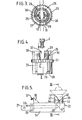
- Figure 5 is a side view of the lamp holder portion of the lamp fitting with a halogen lamp shown in position but in dashed lines,
- Figure 6 is a sectional view on the line VI-VI in Figure 5 but on a slightly larger scale and
- Figure 7 is a plan view of the lamp holder of Figure 5.
- Referring first to Figure 1, therein can be seen a low voltage track lighting system having a mains transformer 1, a track 2 connected by wires 3 to the low voltage side of the transformer 1 and a lamp fitting 4 attached to the track 2. The track 2 has two copper conductor rails 5, as best seen in Figure 2, to each of which one of the wires 2 is connected. The rails 5 are accommodated in
grooves 6 on either side of a central web 7 of a plastics material extrusion. The extrusion hasupper parts 8, in effect forming a flange which gives the extrusion a T configuration. The upper parts are accommodated in a second channel shapedextrusion 9 of the same plastics material withlips 10 at its mouth. As shown the second extrusion is adhered by double-sided self-adhesive tape 11 to a ceiling 12. The track 2 rests on thelips 10. It may be either manipulated - onepart 8 first - or snapped into engagement with thesecond extrusion 9. The second extrusion and the track 2 are together referred to as a two part track. The top 13 of the first extrusion between theparts 8, is recessed to accommodate a screw head if thesecond extrusion 9 is thereby secured. - The fitting 4 has a pair of brass flat-faced
elongate contacts 14, see also Figure 3, which are flat-faced to be complementarily shaped to the flat copper conductor rails 6. The contacts are urged in the direction of the arrows A, see below, to make firm contact with therails 6 which by sandwiching the central web 7 provide a rigid abutment. Thecontacts 14 extend down to the bottom of acentral body portion 15, shown dashed in Figure 2, of the fitting where they are mechanically secured. They have resilience whereby in the absence of the urging they spring away from the conductor rails 6. One of thecontacts 14 at its lower end is abutted by a rivetedrod 16 which passes through the other contact with an insulating gap to terminate in another rivet head on the outside of a flat,bent copper element 17 on the surface of anangle bracket 18 of insulating material. A further flat,bent copper element 19 extends on the opposite faces of thebracket 18. Where therod 16 passes through the other contact and theother element 19, which also is provided with an insulating gap from the rod, the contact and element make electrical contact as they surround therod 16 in annular form. The rod is riveted only so tight as to hold thebracket 18 firmly to thecentral body portion 15, whereby the bracket can be turned to any angle without limit with respect to the body portion with electrical contact maintained at all times between the one contact and theelement 17 via therod 16 and between the other contact and theother element 19 at theirannular portions 20. - An exactly similar angularly adjustable connector is provided between the other end of the
bracket 18 and alug 21 on alamp holder 22, see Figure 5. Therod 23 in this connector has aspring 24 under one of its heads to increase frictional contact so that the lamp holder will maintain the angular orientation to which it is turned. It will be appreciated that except as restricted by fouling of thelug 21 with thebracket 18 in the region of therod 16 thelamp holder 22 can be turned to any orientation required. - Referring now to Figure 3, the cam arrangement for urging the contacts in the direction of arrows A will now be described. Each contact has an
outer lug 25 which extends out through itsown guide portion 26 of the centralcylindrical body 15. Acam sleeve 27 is mounted for twisting movement around thebody 15, the sleeve being retained on thebody 15 by pegs 28 - shown dashed in Figure 4 - which engage circumferentiallyshort grooves 29 in the body. The extent of thegrooves 29 limits the amount of twisting action available.Cam portions 30 of thesleeve 27 extend up outside theguide portions 26. The cam sleeve is of polycarbonate material and has sufficient strength when twisted clockwise in Figure 3 to drive thecontacts 14 into firm low ohmic loss contact with the conductor rails 6 - shown dashed in Figure 3. The configuration and resilience of thecam portions 30 is such that when engaged the contact remains held in position. Indeed the engagement is sufficiently firm to support the weight of the lamp fitting 4. - The cam sleeve is provided with a
rubber grip 31. Figure 4 shows the lamp fitting being offered up to the track 2 with the contacts open under their resilience. Once the track is within thegap 32 between the various components, twisting of the grip will initially bring theguide portions 26 into contact with the track whereupon thecentral body 15 will be held still and further twisting will drive thecam portions 30 round and thecontacts 14 in. - Turning now to Figures 5, 6 & 7, the
lamp holder 22 will now be described. Thelug 21 has on its outer side surfaces copper strips 33 connected via the described connector to thecontacts 14. Thelug 21 is a continuation of alamp holder body 34 provided with a pair ofslots 35 and aboss 36 with ascrew 37 for holding a shade 38, shown only in Figure 1. At the opposite end of the body 34 a bayonet-fittingsocket 39 is provided. It has oppositely arrangedslots 40accommodating lugs 41 of aceramic disc 42 in whichlamp contacting pins 43 are set. Aspring 44 urges the disc and pins outwards. Twoapertures 45 divided by apartition 46 are provided in thebody 34. In these apertures extensions of thestrips 33 freely extend. They are bent over on themselves along a 45° line 47 to turn them up towards thepins 43, to a respective one of which each strip is riveted at anangled portion 48. The freedom of the strips in theirapertures 45 allows them to deflect sideways when thepins 43 anddisc 42 are pressed in against thespring 44. Thepartition 46 prevents contact between the two strips. - The invention is not of course restricted to the details of the described embodiment. For instance the
rods
Claims (16)
Applications Claiming Priority (2)
| Application Number | Priority Date | Filing Date | Title |
|---|---|---|---|
| GB8313528 | 1983-05-17 | ||
| GB08313528A GB2150766B (en) | 1983-05-17 | 1983-05-17 | Track lighting |
Publications (2)
| Publication Number | Publication Date |
|---|---|
| EP0129325A2 true EP0129325A2 (en) | 1984-12-27 |
| EP0129325A3 EP0129325A3 (en) | 1985-12-27 |
Family
ID=10542842
Family Applications (1)
| Application Number | Title | Priority Date | Filing Date |
|---|---|---|---|
| EP84303291A Withdrawn EP0129325A3 (en) | 1983-05-17 | 1984-05-16 | Track lighting |
Country Status (2)
| Country | Link |
|---|---|
| EP (1) | EP0129325A3 (en) |
| GB (1) | GB2150766B (en) |
Cited By (12)
| Publication number | Priority date | Publication date | Assignee | Title |
|---|---|---|---|---|
| EP0201091A2 (en) * | 1985-05-08 | 1986-11-12 | Hailo-Werk Rudolf Loh GmbH & Co. KG | Low-voltage light fixture with a halogen lamp |
| DE3620920A1 (en) * | 1986-06-24 | 1988-01-14 | Kurth Egon Dipl Ing Designer | Low-voltage lamp |
| EP0260726A2 (en) * | 1986-09-17 | 1988-03-23 | The Boeing Company | Passenger entertainment system having direct coupled seat receivers |
| EP0279788A2 (en) * | 1987-02-19 | 1988-08-24 | Giampaolo Targetti | A linear structural member having a drawn section and having weight-reducing slots |
| WO1989004437A1 (en) * | 1987-11-04 | 1989-05-18 | Kurt Ribitsch | Low-voltage lighting equipment |
| AU592303B3 (en) * | 1989-07-06 | 1989-11-24 | Peter Noel Cass | Improvements in extra low voltage lighting |
| WO1990011471A1 (en) * | 1987-09-21 | 1990-10-04 | Kaehoenen Matti | Light fitting system |
| EP0404979A1 (en) * | 1989-06-28 | 1991-01-02 | Michael Jordan | Light rail system |
| GB2245698A (en) * | 1990-07-03 | 1992-01-08 | Powerlite Electrical Products | Lighting track system |
| AT407906B (en) * | 1991-07-19 | 2001-07-25 | Ind Und Design Licht Inh Domin | ELECTRIC LIGHTING SYSTEM |
| EP1421315A1 (en) * | 2001-07-31 | 2004-05-26 | Comfort Products, Inc. | Electrical track lighting system |
| US7172332B2 (en) | 2003-02-14 | 2007-02-06 | Tech Lighting L.L.C. | Field bendable line voltage track lighting system |
Families Citing this family (8)
| Publication number | Priority date | Publication date | Assignee | Title |
|---|---|---|---|---|
| IT8620584V0 (en) * | 1986-01-23 | 1986-01-23 | Teknolit Srl | DEVICE FOR THE ELECTRICAL SUPPLY OF LOW SAFETY OPERATING EQUIPMENT USERS. |
| GB2185863B (en) * | 1986-01-28 | 1990-07-18 | Illuma Designs Limited | Tracked lighting systems |
| GB8808950D0 (en) * | 1988-04-15 | 1988-05-18 | Marlin Lighting Ltd | Articulated support for lamp &c |
| GB2230385B (en) * | 1989-04-08 | 1993-10-13 | Festo Kg | A control device |
| DE4013863A1 (en) * | 1990-04-30 | 1991-10-31 | Staff Gmbh & Co Kg | ADAPTER FOR TRACK RAILS |
| DE4108158C2 (en) * | 1991-03-14 | 2002-11-28 | Festo Ag & Co | Linear drive device |
| DE9111003U1 (en) * | 1991-09-05 | 1991-12-19 | Popp + Co Gmbh, 8582 Bad Berneck, De | |
| GB2355061A (en) * | 1999-09-17 | 2001-04-11 | Kazuhiro Yamanaka | A lamp constructed from electrically conducting elements |
Citations (7)
| Publication number | Priority date | Publication date | Assignee | Title |
|---|---|---|---|---|
| DE815998C (en) * | 1950-02-26 | 1951-10-08 | Robert Kubik | Horizontally movable suspension device for electric ceiling lights |
| US2617849A (en) * | 1949-10-19 | 1952-11-11 | Edward N Wright | Electric outlet molding with movable outlet |
| US3321730A (en) * | 1964-09-21 | 1967-05-23 | Donald M Schlangen | Tree lighting apparatus |
| FR2152153A5 (en) * | 1971-09-06 | 1973-04-20 | Nokia Oy Ab | |
| FR2346874A1 (en) * | 1976-04-01 | 1977-10-28 | Nokia Oy Ab | CORNER CONNECTOR FOR CONDUCTIVE TRACKS |
| US4099817A (en) * | 1977-01-27 | 1978-07-11 | Donald J. Booty | Track lighting |
| DE3120267A1 (en) * | 1981-05-21 | 1982-12-16 | Lichtplanung Dinnebier Kg, 5600 Wuppertal | Holder for electrical incandescent-lamp sockets (lamp holders, holders) on busbars (1). The invention relates to a holder for electrical incandescent-lamp sockets on busbars (1) and, in order to achieve an improved shape. |
-
1983
- 1983-05-17 GB GB08313528A patent/GB2150766B/en not_active Expired
-
1984
- 1984-05-16 EP EP84303291A patent/EP0129325A3/en not_active Withdrawn
Patent Citations (7)
| Publication number | Priority date | Publication date | Assignee | Title |
|---|---|---|---|---|
| US2617849A (en) * | 1949-10-19 | 1952-11-11 | Edward N Wright | Electric outlet molding with movable outlet |
| DE815998C (en) * | 1950-02-26 | 1951-10-08 | Robert Kubik | Horizontally movable suspension device for electric ceiling lights |
| US3321730A (en) * | 1964-09-21 | 1967-05-23 | Donald M Schlangen | Tree lighting apparatus |
| FR2152153A5 (en) * | 1971-09-06 | 1973-04-20 | Nokia Oy Ab | |
| FR2346874A1 (en) * | 1976-04-01 | 1977-10-28 | Nokia Oy Ab | CORNER CONNECTOR FOR CONDUCTIVE TRACKS |
| US4099817A (en) * | 1977-01-27 | 1978-07-11 | Donald J. Booty | Track lighting |
| DE3120267A1 (en) * | 1981-05-21 | 1982-12-16 | Lichtplanung Dinnebier Kg, 5600 Wuppertal | Holder for electrical incandescent-lamp sockets (lamp holders, holders) on busbars (1). The invention relates to a holder for electrical incandescent-lamp sockets on busbars (1) and, in order to achieve an improved shape. |
Cited By (18)
| Publication number | Priority date | Publication date | Assignee | Title |
|---|---|---|---|---|
| EP0201091A2 (en) * | 1985-05-08 | 1986-11-12 | Hailo-Werk Rudolf Loh GmbH & Co. KG | Low-voltage light fixture with a halogen lamp |
| EP0201091A3 (en) * | 1985-05-08 | 1989-01-04 | Hailo-Werk Rudolf Loh GmbH & Co. KG | Low-voltage light fixture with a halogen lamp |
| DE3620920A1 (en) * | 1986-06-24 | 1988-01-14 | Kurth Egon Dipl Ing Designer | Low-voltage lamp |
| EP0260726A2 (en) * | 1986-09-17 | 1988-03-23 | The Boeing Company | Passenger entertainment system having direct coupled seat receivers |
| EP0260726A3 (en) * | 1986-09-17 | 1989-06-14 | The Boeing Company | Passenger entertainment system having direct coupled seat receivers |
| EP0279788A2 (en) * | 1987-02-19 | 1988-08-24 | Giampaolo Targetti | A linear structural member having a drawn section and having weight-reducing slots |
| EP0279788A3 (en) * | 1987-02-19 | 1991-03-20 | Giampaolo Targetti | A linear structural member having a drawn section and having weight-reducing slots |
| WO1990011471A1 (en) * | 1987-09-21 | 1990-10-04 | Kaehoenen Matti | Light fitting system |
| WO1989004437A1 (en) * | 1987-11-04 | 1989-05-18 | Kurt Ribitsch | Low-voltage lighting equipment |
| EP0404979A1 (en) * | 1989-06-28 | 1991-01-02 | Michael Jordan | Light rail system |
| AU592303B3 (en) * | 1989-07-06 | 1989-11-24 | Peter Noel Cass | Improvements in extra low voltage lighting |
| GB2245698A (en) * | 1990-07-03 | 1992-01-08 | Powerlite Electrical Products | Lighting track system |
| GB2245698B (en) * | 1990-07-03 | 1994-08-31 | Powerlite Electrical Products | Lighting track system |
| AT407906B (en) * | 1991-07-19 | 2001-07-25 | Ind Und Design Licht Inh Domin | ELECTRIC LIGHTING SYSTEM |
| EP1421315A1 (en) * | 2001-07-31 | 2004-05-26 | Comfort Products, Inc. | Electrical track lighting system |
| EP1421315A4 (en) * | 2001-07-31 | 2007-02-21 | Comfort Prod Inc | Electrical track lighting system |
| US7172332B2 (en) | 2003-02-14 | 2007-02-06 | Tech Lighting L.L.C. | Field bendable line voltage track lighting system |
| US8033711B2 (en) | 2003-02-14 | 2011-10-11 | Tech Lighting L.L.C. | Field bendable line voltage track lighting system |
Also Published As
| Publication number | Publication date |
|---|---|
| GB8313528D0 (en) | 1983-06-22 |
| EP0129325A3 (en) | 1985-12-27 |
| GB2150766B (en) | 1987-11-18 |
| GB2150766A (en) | 1985-07-03 |
Similar Documents
| Publication | Publication Date | Title |
|---|---|---|
| EP0129325A2 (en) | Track lighting | |
| US4861273A (en) | Low-voltage miniature track lighting system | |
| US5154509A (en) | Low voltage magnetic track light system | |
| US7172332B2 (en) | Field bendable line voltage track lighting system | |
| US4758173A (en) | Socket adaptor for fluorescent lamp | |
| US5833358A (en) | Extruded track lighting system | |
| US4979081A (en) | Electrical supply system | |
| US4674015A (en) | Fluorescent light fixture with removable ballast | |
| US5785411A (en) | Track lighting system | |
| US6533437B1 (en) | Apparatus, systems, and methods for maintaining power to a light string having light units arranged in series | |
| US7401942B1 (en) | Female electric connector plug apparatus for and method of attachment to flourescent tube luminaire fixture assembly | |
| US4972301A (en) | Vehicle lamp with universal mounting capability | |
| US4654765A (en) | Low voltage lighting system replaceable bulb assembly | |
| US6325645B1 (en) | Lighting rail for lighting objects to be exposed to view | |
| US4778397A (en) | Track lighting system and connecting plug with sliding lock | |
| US5205633A (en) | Vehicle lamp with universal mounting capability | |
| US2285175A (en) | Lamp socket | |
| US4262980A (en) | Lamp holder | |
| US20160178169A1 (en) | Adapter device for retrofitting in lighting arrangements | |
| US4360861A (en) | Baseless lamp socket | |
| US4975071A (en) | Track lighting | |
| US4648675A (en) | Electrical connection apparatus for lighting fixtures | |
| US8944835B2 (en) | Electrical connector | |
| US3327281A (en) | Self-adjusting fluorescent lamp holder assembly | |
| GB2203001A (en) | Improved connection and fixing system for electronic unit |
Legal Events
| Date | Code | Title | Description |
|---|---|---|---|
| PUAI | Public reference made under article 153(3) epc to a published international application that has entered the european phase |
Free format text: ORIGINAL CODE: 0009012 |
|
| AK | Designated contracting states |
Designated state(s): BE CH DE FR GB IT LI SE |
|
| PUAL | Search report despatched |
Free format text: ORIGINAL CODE: 0009013 |
|
| 19A | Proceedings stayed before grant |
Effective date: 19850511 |
|
| AK | Designated contracting states |
Designated state(s): BE CH DE FR GB IT LI SE |
|
| RAP1 | Party data changed (applicant data changed or rights of an application transferred) |
Owner name: ROTAFLEX P.L.C. |
|
| 19F | Resumption of proceedings before grant (after stay of proceedings) |
Effective date: 19860401 |
|
| 17P | Request for examination filed |
Effective date: 19860924 |
|
| 17Q | First examination report despatched |
Effective date: 19880509 |
|
| STAA | Information on the status of an ep patent application or granted ep patent |
Free format text: STATUS: THE APPLICATION IS DEEMED TO BE WITHDRAWN |
|
| 18D | Application deemed to be withdrawn |
Effective date: 19880920 |
|
| RIN1 | Information on inventor provided before grant (corrected) |
Inventor name: TOOTH, JAMES ANTONY |