EP0129262A1 - Magnetic disk drive - Google Patents
Magnetic disk drive Download PDFInfo
- Publication number
- EP0129262A1 EP0129262A1 EP84200677A EP84200677A EP0129262A1 EP 0129262 A1 EP0129262 A1 EP 0129262A1 EP 84200677 A EP84200677 A EP 84200677A EP 84200677 A EP84200677 A EP 84200677A EP 0129262 A1 EP0129262 A1 EP 0129262A1
- Authority
- EP
- European Patent Office
- Prior art keywords
- cartridge
- disk
- drive
- slider
- magnetic disk
- Prior art date
- Legal status (The legal status is an assumption and is not a legal conclusion. Google has not performed a legal analysis and makes no representation as to the accuracy of the status listed.)
- Granted
Links
- 238000003780 insertion Methods 0.000 description 10
- 230000037431 insertion Effects 0.000 description 10
- 238000005266 casting Methods 0.000 description 2
- 238000011109 contamination Methods 0.000 description 2
- 239000000428 dust Substances 0.000 description 1
- 239000007788 liquid Substances 0.000 description 1
- 238000004519 manufacturing process Methods 0.000 description 1
- 230000036316 preload Effects 0.000 description 1
- 238000006748 scratching Methods 0.000 description 1
- 230000002393 scratching effect Effects 0.000 description 1
- 230000000087 stabilizing effect Effects 0.000 description 1
- 239000000758 substrate Substances 0.000 description 1
- 239000010409 thin film Substances 0.000 description 1
Images


Classifications
-
- G—PHYSICS
- G11—INFORMATION STORAGE
- G11B—INFORMATION STORAGE BASED ON RELATIVE MOVEMENT BETWEEN RECORD CARRIER AND TRANSDUCER
- G11B17/00—Guiding record carriers not specifically of filamentary or web form, or of supports therefor
- G11B17/02—Details
- G11B17/04—Feeding or guiding single record carrier to or from transducer unit
- G11B17/041—Feeding or guiding single record carrier to or from transducer unit specially adapted for discs contained within cartridges
- G11B17/043—Direct insertion, i.e. without external loading means
-
- G—PHYSICS
- G11—INFORMATION STORAGE
- G11B—INFORMATION STORAGE BASED ON RELATIVE MOVEMENT BETWEEN RECORD CARRIER AND TRANSDUCER
- G11B17/00—Guiding record carriers not specifically of filamentary or web form, or of supports therefor
- G11B17/02—Details
- G11B17/022—Positioning or locking of single discs
- G11B17/028—Positioning or locking of single discs of discs rotating during transducing operation
- G11B17/032—Positioning by moving the door or the cover
-
- G—PHYSICS
- G11—INFORMATION STORAGE
- G11B—INFORMATION STORAGE BASED ON RELATIVE MOVEMENT BETWEEN RECORD CARRIER AND TRANSDUCER
- G11B23/00—Record carriers not specific to the method of recording or reproducing; Accessories, e.g. containers, specially adapted for co-operation with the recording or reproducing apparatus ; Intermediate mediums; Apparatus or processes specially adapted for their manufacture
- G11B23/02—Containers; Storing means both adapted to cooperate with the recording or reproducing means
- G11B23/03—Containers for flat record carriers
- G11B23/032—Containers for flat record carriers for rigid discs
- G11B23/0321—Containers for flat record carriers for rigid discs rigid cartridges for single discs
Definitions
- This invention relates to a magnetic disk drive of the type which reads and writes magnetically recorded information for a flexible magnetic disk contained in a cartridge, the drive having a magnetic head and means for rotating the disk in read/write relationship with the magnetic head.
- the cartridge for a floppy disk includes a relatively thin, flexible jacket which is inserted into the floppy disk drive.
- the disk drive clamps the flexible disk onto a motor shaft which rotates the disk which is contacted by a read/write head.
- This cartridge exposes certain areas of the disk recording surface to dust contamination, liquid spillage, fingerprints, and scratching.
- the flexible jacket allows the possibility of mechanical damage to the entire disk.
- floppy disk drives which accept this type of flexible cartridge are shown in US Patents 3,990,111 (Elliott), 3,678,481 (Dalziel et al), 3,815,150 (Stoddard et al), 4,125,883 (Rolph), and 4,089,029 (Castrodale et al).
- Floppy disk drives have the great advantage of ease of insertion and changing the magnetic disk cartridge so that the operator can select the disk cartridge upon which the drive is to operate.
- the present day floppy disk drives are not capable of operating with the precision, high speed and reliability which is present in the rigid disk drives.
- Floppy disk drives usually have linear actuators with access for the actuator being provided through an opening in the cartridge.
- US Patent 4,074,330 shows a disk drive having a Bernoulli plate for stabilizing a flexible disk to prevent flutter and to maintain an air bearing, but there is no cartridge holding the disk.
- Rigid disk drives such as the IBM 3350, usually have a fixed rigid magnetic medium.
- the magnetic heads do not contact the magnetic surface, but ride on a thin film of air. Because of this, and other features, these disk drives are capable of extremely precise and high speed operation.
- United States Patent specification -A- 4131199 describes a magnetic disk drive which reads and writes magnetically recorded information for a flexible magnetic disk contained in a cartridge which contains a Bernoulli plate, and is consequently expensive to manufacture.
- a magnetic disk drive of the type defined hereinbefore is characterised in that a Bernoulli plate is fixed in the drive with an edge thereof in proximity to an opening in the drive through which the cartridge is inserted so that the edge of the plate enters the cartridge through an edge thereof to position the flexible disk against the plate, and that the means for for rotating the disk rotate the disk against the plate.
- the Bernoulli plate enters the cartridge through a normally closed edge of the cartridge.
- the flexible disk is rotated against the Bernoulli plate with the read/write head floating on an air bearing above the surface of the magnetic disk.
- the head prefererably protrudes through the Bernoulli plate, so that both the Bernoulli plate and the head are on the same side of the disk.
- the slider When the cartridge is out of the disk drive, the slider is preferably locked in the closed position to prevent contamination of, or tampering with, the flexible disk surface. This locking mechanism is released by engagement with the Bernoulli plate when the cartridge is inserted into the drive.
- the magnetic disk cartridge 10 shown in Figure 2 comprises a rigid box containing a flexible magnetic disk 11.
- the box has an opening 12 in one side through which the head and spindle have access to the rotating disk, after the cartridge has been inserted into the disk drive 13.
- a slider 14 normally closes the opening 12.
- a Bernoulli plate 15 (Fig 4) engages the slider 14 to move the slider to an open position in which the disk is rotated by the motor 16 in read/write relationship with a magnetic head (not shown).
- the slider 14 has (Fig 3) a flat portion 17 which normally closes the opening 12 in the cartridge top 18.
- the box also has an open edge 19. This is normally closed by the ridge portion 20 of the slider.
- the ridge portion 20 has two recesses ramps 21 and 22.
- two tapered points 23 and 24 on the Bernoulli plate 15 engage the recessed ramps 21 and 22. This lifts the slider 14 out of the opening 19 in the edge so that the plate 15 enters the cartridge through the edge opening.
- a locking mechanism securely locks the slider in the closed position until the cartridge is inserted into the drive.
- This locking mechanism incudes detents 25 and 26 on the sides of the slider 14. These detents normally engage locking recesses 27 and 28 inside the side edges of the cartridge.
- the detents include arrow- shaped members 29 and 30 each of which has an outside ledge which engages the locking recess (27 or 28) and an inside ledge which engages a tab (31 or 32) on the Bernoulli plate 15.
- ramps 33 and 34 on the Bernoulli plate engage the outside surfaces of the arrow members 29 and 30 to move them inwardly.
- the rigid box making up the cartridge completely covers and protects the magnetic disk 11.
- the slider is locked securely and can only be opened by inserting the cartridge into the disk drive or by a special tool designed specifically for that purpose.
- the mechanism which accomplishes this is not apaprent to the user and this reduces the possibility of the user tampering with the magnetic disk.
- the magnetic disk 11 has (Fig 2) a hub 36 which is magnetically engaged by the shaft of the disk motor.
- This hub 36 is positioned in a moulded hub recess 37.
- a protrusion 38 on the inside of the flat portion of the slider retains the hub 36 in the hub recess 37 when the slider is in the closed position.
- the flat surface of the Bernoulli plate 15 engages the disk to maintain the hub 36 in the hub recess 37.
- the edges 42 and 43 of the Bernoulli plate travel along internal grooves 40 and 41 along the sides of the cartridge. This guides the cartridge into proper position.
- External guide grooves 44 and 45 engage guide tracks 46 and 47 in the drive.
- the external grooves 44 and 45 run the length of the cartridge base. If an attempt is made to insert the cartridge upside down, interference prevents insertion.
- the ridge portion 20 of the slider must pass beneath triangular bumps 48 and 49 on guide brackets 50 and 51 (Fig 5). (Bump 48 protrudes through hole 48a into the cartridge insertion path.) During removal, this ensures that the front edge of the slider is seated on the front edge and the slider 14 is securely locked. If an attempt is made to insert a partially opened cartridge, the ridge portion 20 interferes with bumps 48 and 49, thereby preventing insertion of a cartridge in faulty condition.
- the front edge of the slider is preloaded against the front edge of the cartridge base 51 by preload springs 55 and 56. This avoids a gap along the front edge of the cartridge.
- Second springs 57 and 58 seal the triangular space between the cartridge top 18 and the slider 14. The springs 57 and 58 prevent the insertion of a cartridge which has an open slider.
- a cut-away 59 at the front of the cartridge base ensures clearance between the magnetic head and the cartridge during insertion even if the cartridge base 51 is slightly warped.
- Stops 60 and 61 are moulded into the cartridge base to limit the motion during insertion.
- the stops register on shoulders 62 and 63 of the Bernoulli plate. This accurately positions the cartrdige prior to engaging the drive motor.
- the magnetic disk cartridge registers the magnetic disk next to the Bernoulli plate 15 in the disk drive so that the magnetic disk 11 can be rotated in proximity to the plate 15 in a manner which stablizes the flexible disk 11 for the purpose of recording.
Landscapes
- Feeding And Guiding Record Carriers (AREA)
- Holding Or Fastening Of Disk On Rotational Shaft (AREA)
Abstract
Description
- This invention relates to a magnetic disk drive of the type which reads and writes magnetically recorded information for a flexible magnetic disk contained in a cartridge, the drive having a magnetic head and means for rotating the disk in read/write relationship with the magnetic head.
- Recently, magnetic disk drives which write and read digital data from flexible magnetic disks ("floppy disks") have been extensively used for small, so-called microcomputer, systems, for word-processing applications and the like. Typically, the cartridge for a floppy disk includes a relatively thin, flexible jacket which is inserted into the floppy disk drive. The disk drive clamps the flexible disk onto a motor shaft which rotates the disk which is contacted by a read/write head. This cartridge exposes certain areas of the disk recording surface to dust contamination, liquid spillage, fingerprints, and scratching. Also, the flexible jacket allows the possibility of mechanical damage to the entire disk. Examples of floppy disk drives which accept this type of flexible cartridge are shown in US Patents 3,990,111 (Elliott), 3,678,481 (Dalziel et al), 3,815,150 (Stoddard et al), 4,125,883 (Rolph), and 4,089,029 (Castrodale et al). Floppy disk drives have the great advantage of ease of insertion and changing the magnetic disk cartridge so that the operator can select the disk cartridge upon which the drive is to operate. However, the present day floppy disk drives are not capable of operating with the precision, high speed and reliability which is present in the rigid disk drives. Floppy disk drives usually have linear actuators with access for the actuator being provided through an opening in the cartridge. US Patent 4,074,330 (Norton et al) shows a disk drive having a Bernoulli plate for stabilizing a flexible disk to prevent flutter and to maintain an air bearing, but there is no cartridge holding the disk.
- Rigid disk drives, such as the IBM 3350, usually have a fixed rigid magnetic medium. The magnetic heads do not contact the magnetic surface, but ride on a thin film of air. Because of this, and other features, these disk drives are capable of extremely precise and high speed operation.
- High speed and precision are also achieved in minicomputer disk drives which accept rigid cartridges, or disk packs, which enclose and protect the rotating magnetic disk. In such disk packs, the magnetic disk surface is mounted on a precision rigid substrate which is rotatable inside the disk packs. These disk packs are expensive and they cannot be changed on the machine with the same ease with which the so-called "floppy" disk cartridges can be inserted and removed.
- United States Patent specification -A- 4131199 describes a magnetic disk drive which reads and writes magnetically recorded information for a flexible magnetic disk contained in a cartridge which contains a Bernoulli plate, and is consequently expensive to manufacture.
- It is an object of the present invention to provide a magnetic disk drive for a cartridge which allows easy insertion and removal of the cartridge and high speed reliable performance of the disk drive.
- According to this invention, a magnetic disk drive of the type defined hereinbefore is characterised in that a Bernoulli plate is fixed in the drive with an edge thereof in proximity to an opening in the drive through which the cartridge is inserted so that the edge of the plate enters the cartridge through an edge thereof to position the flexible disk against the plate, and that the means for for rotating the disk rotate the disk against the plate.
- When a suitable cartridge is inserted into the disk drive it engages the Bernoulli plate. This plate engages a slider on the cartridge, and as the- cartridge is inserted into the drive, the slider is moved to an open position so that the flexible disk can be engaged by the hub of a motor which rotates the disk and so that the rotating surface is in a read/write relationship with a magnetic head. Access for a rotary head actuator is through this same opening from which the slider is moved. The preferred cartridge is described and claimed in copending European patent application no. 82302071.4, publication no. 0063500.
- As the cartridge is inserted into the drive, the Bernoulli plate enters the cartridge through a normally closed edge of the cartridge. After the cartridge is inserted, the flexible disk is rotated against the Bernoulli plate with the read/write head floating on an air bearing above the surface of the magnetic disk. The head prefererably protrudes through the Bernoulli plate, so that both the Bernoulli plate and the head are on the same side of the disk.
- When the cartridge is out of the disk drive, the slider is preferably locked in the closed position to prevent contamination of, or tampering with, the flexible disk surface. This locking mechanism is released by engagement with the Bernoulli plate when the cartridge is inserted into the drive.
- One embodiment of the invention will now be described, by way of example, with reference to the accompanying drawings, in which:
- Fig 1 is a front perspective view of the disk drive;
- Fig 2 is an exploded view of the cartridge and disk;
- Fig 3 is an exploded view of the cartridge;
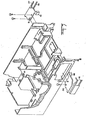
- Fig 4 is a perspective view from beneath of the base casting and Bernoulli plate;
- Fig 5 is a perspective view of the casting from above the other side.
- The
magnetic disk cartridge 10 shown in Figure 2 comprises a rigid box containing a flexible magnetic disk 11. The box has an opening 12 in one side through which the head and spindle have access to the rotating disk, after the cartridge has been inserted into thedisk drive 13. Aslider 14 normally closes theopening 12. When thecartridge 10 is inserted into thedrive 13, a Bernoulli plate 15 (Fig 4) engages theslider 14 to move the slider to an open position in which the disk is rotated by themotor 16 in read/write relationship with a magnetic head (not shown). - The
slider 14 has (Fig 3) aflat portion 17 which normally closes the opening 12 in thecartridge top 18. When the cartridge is inserted in the drive, access to the disk for rotation and reading/writing is through theopening 12. The box also has anopen edge 19. This is normally closed by theridge portion 20 of the slider. Theridge portion 20 has two recesses ramps 21 and 22. When the cartridge is inserted into the drive, twotapered points plate 15 engage therecessed ramps slider 14 out of theopening 19 in the edge so that theplate 15 enters the cartridge through the edge opening. - A locking mechanism securely locks the slider in the closed position until the cartridge is inserted into the drive. This locking mechanism incudes detents 25 and 26 on the sides of the
slider 14. These detents normally engagelocking recesses shaped members plate 15. When the cartridge is inserted into the drive, ramps 33 and 34 on the Bernoulli plate engage the outside surfaces of thearrow members locking recess tabs 31 and 32 on the Bernoulli plate engage the inside ledges of thearrow members tabs 31 and 32 with the inside ledges of thearrow members arrow members locking recess - When the
slider 14 is in the closed and locked position, the rigid box making up the cartridge completely covers and protects the magnetic disk 11. The slider is locked securely and can only be opened by inserting the cartridge into the disk drive or by a special tool designed specifically for that purpose. The mechanism which accomplishes this is not apaprent to the user and this reduces the possibility of the user tampering with the magnetic disk. - The magnetic disk 11 has (Fig 2) a
hub 36 which is magnetically engaged by the shaft of the disk motor. Thishub 36 is positioned in a moulded hub recess 37. Aprotrusion 38 on the inside of the flat portion of the slider retains thehub 36 in the hub recess 37 when the slider is in the closed position. As the cartridge is inserted into the drive, thereby moving the slider to the open position, the flat surface of the Bernoulliplate 15 engages the disk to maintain thehub 36 in the hub recess 37. - As the cartridge is inserted into the disk drive, the
edges internal grooves External guide grooves guide tracks external grooves - During insertion or removal, the
ridge portion 20 of the slider must pass beneathtriangular bumps guide brackets 50 and 51 (Fig 5). (Bump 48 protrudes through hole 48a into the cartridge insertion path.) During removal, this ensures that the front edge of the slider is seated on the front edge and theslider 14 is securely locked. If an attempt is made to insert a partially opened cartridge, theridge portion 20 interferes withbumps - For assembly purposes, there are two raised areas, 52 and 53, at the rear of the cartridge base 51 (Fig 3). These aid in properly positioning the
cartridge top 18. - The front edge of the slider is preloaded against the front edge of the
cartridge base 51 by preload springs 55 and 56. This avoids a gap along the front edge of the cartridge. Second springs 57 and 58 seal the triangular space between thecartridge top 18 and theslider 14. Thesprings - A cut-away 59 at the front of the cartridge base ensures clearance between the magnetic head and the cartridge during insertion even if the
cartridge base 51 is slightly warped. -
Stops shoulders - The magnetic disk cartridge registers the magnetic disk next to the
Bernoulli plate 15 in the disk drive so that the magnetic disk 11 can be rotated in proximity to theplate 15 in a manner which stablizes the flexible disk 11 for the purpose of recording.
Claims (2)
Applications Claiming Priority (2)
| Application Number | Priority Date | Filing Date | Title |
|---|---|---|---|
| US256320 | 1981-04-22 | ||
| US06/256,320 US4400748A (en) | 1981-04-22 | 1981-04-22 | Flexible magnetic disk drive using a rigid cartridge |
Related Parent Applications (1)
| Application Number | Title | Priority Date | Filing Date |
|---|---|---|---|
| EP82302071.4 Division | 1982-04-22 |
Publications (2)
| Publication Number | Publication Date |
|---|---|
| EP0129262A1 true EP0129262A1 (en) | 1984-12-27 |
| EP0129262B1 EP0129262B1 (en) | 1987-02-04 |
Family
ID=22971806
Family Applications (2)
| Application Number | Title | Priority Date | Filing Date |
|---|---|---|---|
| EP82302071A Expired EP0063500B1 (en) | 1981-04-22 | 1982-04-22 | Magnetic disk cartridge |
| EP84200677A Expired EP0129262B1 (en) | 1981-04-22 | 1982-04-22 | Magnetic disk drive |
Family Applications Before (1)
| Application Number | Title | Priority Date | Filing Date |
|---|---|---|---|
| EP82302071A Expired EP0063500B1 (en) | 1981-04-22 | 1982-04-22 | Magnetic disk cartridge |
Country Status (7)
| Country | Link |
|---|---|
| US (1) | US4400748A (en) |
| EP (2) | EP0063500B1 (en) |
| JP (1) | JPS57181484A (en) |
| AU (1) | AU550644B2 (en) |
| CA (1) | CA1188284A (en) |
| DE (1) | DE3272275D1 (en) |
| IL (1) | IL65547A (en) |
Families Citing this family (27)
| Publication number | Priority date | Publication date | Assignee | Title |
|---|---|---|---|---|
| US4658318A (en) * | 1981-04-22 | 1987-04-14 | Iomega Corporation | Magnetic disk cartridge having improved locking mechanism and ringing pad |
| AU560481B2 (en) * | 1982-07-19 | 1987-04-09 | Sony Corporation | Disk cassette loading |
| US4768124A (en) * | 1982-11-09 | 1988-08-30 | Iomega Corporation | Record disk cartridge with flexible pad |
| US4717981A (en) * | 1983-08-04 | 1988-01-05 | Syquest Technology | Hard disc cartridge arrangement with an automatically activated door |
| US4663686A (en) * | 1984-01-23 | 1987-05-05 | Iomega Corporation | Head cleaning cartridge for magnetic disk drive |
| US4571718A (en) * | 1984-07-11 | 1986-02-18 | Eastman Kodak Company | Optical disk cartridge and cooperating apparatus |
| NL8402602A (en) * | 1984-08-27 | 1986-03-17 | Philips Nv | DISC CASSETTE. |
| US4969061A (en) * | 1989-01-23 | 1990-11-06 | Iomega Corporation | Particulate removing means for cartridges |
| US5440436A (en) * | 1992-11-13 | 1995-08-08 | Syquest Technology, Inc. | Removable cartridge disk drive with a 1.8 inch form factor |
| US5617397A (en) * | 1994-10-18 | 1997-04-01 | Iomega Corporation | Movable internal platform for a disk drive |
| CA2214435A1 (en) * | 1995-03-03 | 1996-09-12 | Mark S. Thayne | Head park mechanism in a data storage device for preventing accidental damage |
| DE69513143T2 (en) * | 1995-04-18 | 2000-08-17 | Iomega Corp., Roy | Leading backdrop in cassette |
| DE69526810T2 (en) * | 1995-06-07 | 2002-11-21 | Iomega Corp., Roy | Record cassette with anti-rattle process |
| WO1996041344A1 (en) * | 1995-06-07 | 1996-12-19 | Iomega Corporation | Disk cartridge anti-rattle mechanism |
| US5570252A (en) * | 1995-06-07 | 1996-10-29 | Iomega Corporation | Disk drive cartridge door |
| US5671109A (en) * | 1995-06-07 | 1997-09-23 | Iomega Corporation | Disk drive cartridge door |
| US5912786A (en) * | 1996-06-03 | 1999-06-15 | Iomega Corporation | Disk drive apparatus having an improved spindle motor loading mechanism |
| US5969914A (en) | 1997-09-12 | 1999-10-19 | Iomega Corporation | Data storage cartridge and drive with an interlock |
| USD421748S (en) * | 1997-10-27 | 2000-03-21 | Iomega Corporation | Storage disk cartridge |
| USD430575S (en) * | 1997-10-27 | 2000-09-05 | Iomega Corporation | Information storage disk cartridge |
| USD424048S (en) * | 1998-05-12 | 2000-05-02 | Castlewood Systems, Inc. | Video and computer data cartridge |
| USD418828S (en) * | 1998-05-12 | 2000-01-11 | Castlewood Systems, Inc. | Element of an audio, video and computer data cartridge |
| USD411533S (en) | 1998-05-12 | 1999-06-29 | Castlewood Systems, Inc. | Element of an audio video and computer data cartridge |
| USD410644S (en) | 1998-05-12 | 1999-06-08 | Castlewood Systems, Inc. | Audio, video, and computer data cartridge |
| US6014287A (en) * | 1998-05-15 | 2000-01-11 | Iomega Corporation | Speed plate |
| US6141185A (en) * | 1998-08-25 | 2000-10-31 | Iomega Corporation | Anti-rattle mechanism for cartridge |
| US6594430B1 (en) | 2000-05-11 | 2003-07-15 | Carnegie Mellon University | Solid immersion lenses for focusing collimated light in the near-field region |
Citations (5)
| Publication number | Priority date | Publication date | Assignee | Title |
|---|---|---|---|---|
| US3678481A (en) * | 1970-03-13 | 1972-07-18 | Ibm | Data storage apparatus employing a single magnetic disk |
| US3815150A (en) * | 1972-06-23 | 1974-06-04 | Memorex Corp | Flexible disc drive |
| US3975768A (en) * | 1973-06-20 | 1976-08-17 | Genisco Technology Corporation | Removable cartridge flexible disc memory apparatus |
| FR2309012A1 (en) * | 1975-04-21 | 1976-11-19 | Ibm | FLEXIBLE MAGNETIC DISC MEMORY |
| US4125883A (en) * | 1977-09-02 | 1978-11-14 | Memorex Corporation | Apparatus for centering and clamping a flexible magnetic recording disc |
Family Cites Families (8)
| Publication number | Priority date | Publication date | Assignee | Title |
|---|---|---|---|---|
| US3609722A (en) * | 1969-03-19 | 1971-09-28 | George E Zenzefilis | Center sealing data disc cassette and processing machine |
| US3696350A (en) * | 1970-08-27 | 1972-10-03 | William D Cohen | Connected rotatable pliable disk and rigid disk with annular groove for recording using an air bearing |
| JPS5123167B2 (en) * | 1972-02-01 | 1976-07-15 | ||
| DE2330819A1 (en) * | 1972-06-27 | 1974-01-17 | Arvin Ind Inc | MAGNETIC DISC UNIT AND CASSETTE |
| US3990111A (en) * | 1973-10-12 | 1976-11-02 | International Business Machines Corporation | Data storage apparatus employing a flexible magnetic disk |
| US4074330A (en) * | 1976-08-30 | 1978-02-14 | International Business Machines Corporation | Flexible disk storage apparatus |
| US4152740A (en) * | 1977-03-16 | 1979-05-01 | Arvin Industries, Inc. | Magnetic disc recorder and cassette |
| GB1525849A (en) * | 1977-06-29 | 1978-09-20 | Ibm | Record disc cartridge |
-
1981
- 1981-04-22 US US06/256,320 patent/US4400748A/en not_active Expired - Lifetime
-
1982
- 1982-04-15 JP JP57063215A patent/JPS57181484A/en active Granted
- 1982-04-20 IL IL65547A patent/IL65547A/en unknown
- 1982-04-22 DE DE8282302071T patent/DE3272275D1/en not_active Expired
- 1982-04-22 EP EP82302071A patent/EP0063500B1/en not_active Expired
- 1982-04-22 AU AU82935/82A patent/AU550644B2/en not_active Ceased
- 1982-04-22 EP EP84200677A patent/EP0129262B1/en not_active Expired
- 1982-04-22 CA CA000401514A patent/CA1188284A/en not_active Expired
Patent Citations (5)
| Publication number | Priority date | Publication date | Assignee | Title |
|---|---|---|---|---|
| US3678481A (en) * | 1970-03-13 | 1972-07-18 | Ibm | Data storage apparatus employing a single magnetic disk |
| US3815150A (en) * | 1972-06-23 | 1974-06-04 | Memorex Corp | Flexible disc drive |
| US3975768A (en) * | 1973-06-20 | 1976-08-17 | Genisco Technology Corporation | Removable cartridge flexible disc memory apparatus |
| FR2309012A1 (en) * | 1975-04-21 | 1976-11-19 | Ibm | FLEXIBLE MAGNETIC DISC MEMORY |
| US4125883A (en) * | 1977-09-02 | 1978-11-14 | Memorex Corporation | Apparatus for centering and clamping a flexible magnetic recording disc |
Non-Patent Citations (1)
| Title |
|---|
| IBM TECHNICAL DISCLOSURE BULLETIN, vol. 24, no. 1A, june 1981, page 216, New YORK, US; R.B. HENDERSON: "Flexible disk cartridge arrangement" * |
Also Published As
| Publication number | Publication date |
|---|---|
| CA1188284A (en) | 1985-06-04 |
| AU550644B2 (en) | 1986-03-27 |
| JPH0348592B2 (en) | 1991-07-24 |
| JPS57181484A (en) | 1982-11-08 |
| IL65547A (en) | 1985-04-30 |
| AU8293582A (en) | 1982-10-28 |
| US4400748A (en) | 1983-08-23 |
| EP0063500A1 (en) | 1982-10-27 |
| DE3272275D1 (en) | 1986-09-04 |
| IL65547A0 (en) | 1982-07-30 |
| EP0063500B1 (en) | 1986-07-30 |
| EP0129262B1 (en) | 1987-02-04 |
Similar Documents
| Publication | Publication Date | Title |
|---|---|---|
| EP0129262B1 (en) | Magnetic disk drive | |
| US5216558A (en) | Drawer loading removable cartridge disk drive | |
| US5214550A (en) | Miniature removable rigid disk drive and cartridge system | |
| US5691860A (en) | Self sealing structure for a removable disk hard disk drive | |
| US6252740B1 (en) | Disk drive cartridge door | |
| US4459628A (en) | Disk cartridge | |
| EP0739011B1 (en) | Keying slots on cartridge | |
| JPS6271054A (en) | Mechanism for opening/closing shutter of disk cartridge | |
| US5636095A (en) | Removable disk to drive engagement | |
| EP0747900B1 (en) | Disk cartridge anti-rattle mechanism | |
| US4724962A (en) | Disk jacket | |
| US4456935A (en) | Information recording apparatus with a disc loaded in a cassette | |
| US4658318A (en) | Magnetic disk cartridge having improved locking mechanism and ringing pad | |
| EP0063499B1 (en) | Magnetic disk drive having a movable drive motor | |
| US6226150B1 (en) | Data storage cartridge having an interlock mechanism to prevent improper insertion with a cooperating data storage drive | |
| CA1188791A (en) | Flexible magnetic disk drive using a rigid cartridge | |
| KR890006303Y1 (en) | Disk driving apparatus | |
| US4768124A (en) | Record disk cartridge with flexible pad | |
| US4709282A (en) | Device for loading or unloading magnetic disc pack | |
| US5680284A (en) | Center core and shutter for a high density magnetic disk cartridge | |
| US7251104B2 (en) | Recording medium cartridge | |
| JPH10125034A (en) | Disk cartridge | |
| KR850001462B1 (en) | Cartridge | |
| JP2000187919A (en) | Data carrier loader and its loading method | |
| JPH02236861A (en) | Large capacity auxiliary storage/retrieving device |
Legal Events
| Date | Code | Title | Description |
|---|---|---|---|
| PUAI | Public reference made under article 153(3) epc to a published international application that has entered the european phase |
Free format text: ORIGINAL CODE: 0009012 |
|
| AC | Divisional application: reference to earlier application |
Ref document number: 63500 Country of ref document: EP |
|
| AK | Designated contracting states |
Designated state(s): BE CH DE FR GB IT LI NL SE |
|
| 17P | Request for examination filed |
Effective date: 19841129 |
|
| 17Q | First examination report despatched |
Effective date: 19860320 |
|
| GRAA | (expected) grant |
Free format text: ORIGINAL CODE: 0009210 |
|
| AC | Divisional application: reference to earlier application |
Ref document number: 63500 Country of ref document: EP |
|
| AK | Designated contracting states |
Kind code of ref document: B1 Designated state(s): BE CH DE FR GB IT LI NL SE |
|
| ITF | It: translation for a ep patent filed | ||
| REF | Corresponds to: |
Ref document number: 3275419 Country of ref document: DE Date of ref document: 19870312 |
|
| ET | Fr: translation filed | ||
| PG25 | Lapsed in a contracting state [announced via postgrant information from national office to epo] |
Ref country code: SE Effective date: 19870423 |
|
| PG25 | Lapsed in a contracting state [announced via postgrant information from national office to epo] |
Ref country code: LI Effective date: 19870430 Ref country code: CH Effective date: 19870430 |
|
| BERE | Be: lapsed |
Owner name: IOMEGA CORP. Effective date: 19870430 |
|
| PG25 | Lapsed in a contracting state [announced via postgrant information from national office to epo] |
Ref country code: NL Effective date: 19871101 |
|
| PLBE | No opposition filed within time limit |
Free format text: ORIGINAL CODE: 0009261 |
|
| STAA | Information on the status of an ep patent application or granted ep patent |
Free format text: STATUS: NO OPPOSITION FILED WITHIN TIME LIMIT |
|
| NLV4 | Nl: lapsed or anulled due to non-payment of the annual fee | ||
| REG | Reference to a national code |
Ref country code: CH Ref legal event code: PL |
|
| 26N | No opposition filed | ||
| PG25 | Lapsed in a contracting state [announced via postgrant information from national office to epo] |
Ref country code: BE Effective date: 19890430 |
|
| REG | Reference to a national code |
Ref country code: GB Ref legal event code: 711B |
|
| ET1 | Fr: translation filed ** revision of the translation of the patent or the claims | ||
| REG | Reference to a national code |
Ref country code: GB Ref legal event code: 727 |
|
| REG | Reference to a national code |
Ref country code: GB Ref legal event code: 727A |
|
| REG | Reference to a national code |
Ref country code: GB Ref legal event code: 727B |
|
| REG | Reference to a national code |
Ref country code: GB Ref legal event code: SP |
|
| PGFP | Annual fee paid to national office [announced via postgrant information from national office to epo] |
Ref country code: GB Payment date: 19930421 Year of fee payment: 12 |
|
| PGFP | Annual fee paid to national office [announced via postgrant information from national office to epo] |
Ref country code: FR Payment date: 19930430 Year of fee payment: 12 |
|
| PGFP | Annual fee paid to national office [announced via postgrant information from national office to epo] |
Ref country code: DE Payment date: 19930630 Year of fee payment: 12 |
|
| PG25 | Lapsed in a contracting state [announced via postgrant information from national office to epo] |
Ref country code: GB Effective date: 19940422 |
|
| GBPC | Gb: european patent ceased through non-payment of renewal fee |
Effective date: 19940422 |
|
| PG25 | Lapsed in a contracting state [announced via postgrant information from national office to epo] |
Ref country code: FR Effective date: 19941229 |
|
| PG25 | Lapsed in a contracting state [announced via postgrant information from national office to epo] |
Ref country code: DE Effective date: 19950103 |
|
| EUG | Se: european patent has lapsed |
Ref document number: 84200677.7 Effective date: 19880906 |
|
| REG | Reference to a national code |
Ref country code: FR Ref legal event code: ST |