EP0128699A2 - Camera drive - Google Patents
Camera drive Download PDFInfo
- Publication number
- EP0128699A2 EP0128699A2 EP84303608A EP84303608A EP0128699A2 EP 0128699 A2 EP0128699 A2 EP 0128699A2 EP 84303608 A EP84303608 A EP 84303608A EP 84303608 A EP84303608 A EP 84303608A EP 0128699 A2 EP0128699 A2 EP 0128699A2
- Authority
- EP
- European Patent Office
- Prior art keywords
- shutter
- spring
- film
- detent element
- release
- Prior art date
- Legal status (The legal status is an assumption and is not a legal conclusion. Google has not performed a legal analysis and makes no representation as to the accuracy of the status listed.)
- Granted
Links
- 230000000694 effects Effects 0.000 claims description 2
- 230000004913 activation Effects 0.000 claims 1
- 230000001419 dependent effect Effects 0.000 claims 1
- 210000003813 thumb Anatomy 0.000 description 4
- 239000002184 metal Substances 0.000 description 2
Images

Classifications
-
- G—PHYSICS
- G03—PHOTOGRAPHY; CINEMATOGRAPHY; ANALOGOUS TECHNIQUES USING WAVES OTHER THAN OPTICAL WAVES; ELECTROGRAPHY; HOLOGRAPHY
- G03B—APPARATUS OR ARRANGEMENTS FOR TAKING PHOTOGRAPHS OR FOR PROJECTING OR VIEWING THEM; APPARATUS OR ARRANGEMENTS EMPLOYING ANALOGOUS TECHNIQUES USING WAVES OTHER THAN OPTICAL WAVES; ACCESSORIES THEREFOR
- G03B1/00—Film strip handling
Definitions
- This invention relates to disc cameras and its main object is to provide a convenient and simple mechanical drive arrangement which locates the film positively during shutter operation.
- the invention accordingly comprises a manually movable film advance member reciprocable between a rest and an actuated position, and a manually movable shutter release element; spring means; a shutter; drive means actuated by the film advance member on its movement to actuated position to rotate the disc film and activate the spring means; spring retainer means to retain the spring means in activated position and release the spring means to operate the shutter on actuation of the shutter release element, and a spring urged film detent element actuated by the drive means and on release of the spring means whereby the detent element is urged against the film during the latter part of its advance so as to engage a film detent opening when the latter comes into register, and the detent element is withdrawn from the opening after the shutter is operated.
- a stop movable with the detent element blocks shutter movement when the detent element is in its withdrawn position.
- a reciprocable member 1 comprising a thumb slide 2 and a rack 3 is urged by a spring 4 to a rest position ( Figure 1) and movable manually to an actuated position ( Figure 4).
- a film drive spindle (not shown) is concentric with and driven through a ratchet (not shown) by a main gear member 5 meshing with a second gear member 6 meshing in turn with the rack 3.
- Rack 3 and gear members 5, 6 are situated in a first plane.
- a pin 7 on the main gear member 5 is positioned for engaging a shoulder 10 on one arm 11 of a 3-arm lever 12 pivoted at 13 for movement in a second plane parallel to that of the gear member 5.
- the lever 12 has an operating arm 14 carrying one end of a tension spring 15 anchored at 16.
- a retainer arm 17, also part of the 3-arm lever 12 co-operates with a one arm 19 of a retainer element 20 in the form of a bell crank 20 pivoted at 21 and urged by an integral leaf spring 22 towards the retainer arm. All these levers are in the second plane.
- Operating arm 14 of the 3-arm lever 12 terminates in a striker 25 co-operating with a shoulder 26 on one arm 27 of a V-shaped lever 29 urged to the Figure 5 position by an integral leaf spring 30 and pivoted intermediately at 31.
- the end 32 of the lever 29 opposite shoulder 26 is connected by a pin 33 to a slide 34 movable in the first plane.
- the slide 34 has its lower end (in the orientation illustrated) formed as a cam 35 to actuate a follower plate 36, floating in a cavity and urged downwardly (as illustrated) by a spring 37.
- the follower plate 36 carries a detent pin 40 directed towards film in the camera, and a lip 41.
- a metal shutter plate 42 pivoted at 43 and spring urged to the closed position illustrated has an operating arm 44 in way of a metal striker 45 on the operating arm 14 of the 3-arm lever 12.
- a projection 46 on the shutter plate co-operates with the lip 41 on the follower plate 36.
Landscapes
- Physics & Mathematics (AREA)
- General Physics & Mathematics (AREA)
- Shutters For Cameras (AREA)
- Details Of Cameras Including Film Mechanisms (AREA)
- Lens Barrels (AREA)
- Valve Device For Special Equipments (AREA)
- Vehicle Body Suspensions (AREA)
- Reciprocating, Oscillating Or Vibrating Motors (AREA)
Abstract
Description
- This invention relates to disc cameras and its main object is to provide a convenient and simple mechanical drive arrangement which locates the film positively during shutter operation.
- The invention accordingly comprises a manually movable film advance member reciprocable between a rest and an actuated position, and a manually movable shutter release element; spring means; a shutter; drive means actuated by the film advance member on its movement to actuated position to rotate the disc film and activate the spring means; spring retainer means to retain the spring means in activated position and release the spring means to operate the shutter on actuation of the shutter release element, and a spring urged film detent element actuated by the drive means and on release of the spring means whereby the detent element is urged against the film during the latter part of its advance so as to engage a film detent opening when the latter comes into register, and the detent element is withdrawn from the opening after the shutter is operated.
- Preferably a stop movable with the detent element blocks shutter movement when the detent element is in its withdrawn position.
- One embodiment of the invention will now be described with reference to the accompanying drawings in which
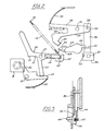
- Figure 1 is a diagrammatic elevation showing movable parts associated with the film advance means, drive means and spring in the film- advanced, spring-tensioned condition;
- Figure 2 is a diagrammatic elevation showing the spring, spring retainer and release means, film detent element and shutter, in the spring-tensioned condition ready for film exposure;
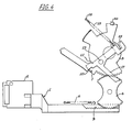
- Figure 3 is a side view of the detent element and associated parts in the spring-tensioned detenting condition;
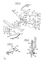
- Figures 4, 5 and 6 are views corresponding to Figures 1, 2 and 3 showing the same parts in the spring-released film exposed condition ready for film advance; and
- Figure 7 is a perspective detail showing co-operation of shutter and detent member.
- Referring to the drawings, a reciprocable member 1 comprising a
thumb slide 2 and arack 3 is urged by aspring 4 to a rest position (Figure 1) and movable manually to an actuated position (Figure 4). A film drive spindle (not shown) is concentric with and driven through a ratchet (not shown) by a main gear member 5 meshing with asecond gear member 6 meshing in turn with therack 3.Rack 3 andgear members 5, 6 are situated in a first plane. - A
pin 7 on the main gear member 5 is positioned for engaging ashoulder 10 on onearm 11 of a 3-arm lever 12 pivoted at 13 for movement in a second plane parallel to that of the gear member 5. Thelever 12 has anoperating arm 14 carrying one end of atension spring 15 anchored at 16. Aretainer arm 17, also part of the 3-arm lever 12 co-operates with a onearm 19 of aretainer element 20 in the form of abell crank 20 pivoted at 21 and urged by anintegral leaf spring 22 towards the retainer arm. All these levers are in the second plane. When thethumb slide 2 is reciprocated to its actuatedpostion pin 7 moves 3-arm lever 12 to tension thespring 15, andretainer arm 17 cams back thearm 19 ofbell crank 20 until it engages in a notch 23 in that arm, which prevents release of the spring. -
Operating arm 14 of the 3-arm lever 12 terminates in astriker 25 co-operating with ashoulder 26 on onearm 27 of a V-shaped lever 29 urged to the Figure 5 position by anintegral leaf spring 30 and pivoted intermediately at 31. Theend 32 of thelever 29 oppositeshoulder 26 is connected by apin 33 to aslide 34 movable in the first plane. Theslide 34 has its lower end (in the orientation illustrated) formed as acam 35 to actuate afollower plate 36, floating in a cavity and urged downwardly (as illustrated) by aspring 37. Thefollower plate 36 carries adetent pin 40 directed towards film in the camera, and alip 41. - A
metal shutter plate 42 pivoted at 43 and spring urged to the closed position illustrated has anoperating arm 44 in way of ametal striker 45 on theoperating arm 14 of the 3-arm lever 12. Aprojection 46 on the shutter plate co-operates with thelip 41 on thefollower plate 36. - As the
thumb slide 2 is moved to actuated position to tension thespring 16 thestriker 25 onoperating arm 14 withdraws fromarm 27 of V-lever 29 and thespring 30 moves thearm 27 downwards until theother arm 48 of the V-lever meets a fixedabutment pin 49.slide 34 moves upwards, withdrawingcam 35 so that, after a certain initial movement of theslide 34 thefollower plate 36 moves to bring thedetent pin 40 against the film, which at this point is turning to its new position. Thepin 40 engages the next notch in the film and holds the film firmly in position. Thelip 41 onplate 36 moves out of the way of theprojection 45 on theshutter plate 42. - Release of the
thumb slide 42 to its initial position has no direct effect, but a second actuating movement is prevented bypin 50 on the main gear member 5 engaging the end ofarm 48 of the V-lever 29. - Release movement of
bell crank 20 is initiated by camming action of a shutter release button B which moves thelever 51 of the bell crank clockwise (as shown) to release the 3-arm lever 12. Operatingarm 14 of the 3-arm lever then moves counter-clockwise rapidly under action of thespring 15.Striker 45 operates theshutter plate 42 as it moves past theoperating arm 44 thereof andstriker 25 then moves the V-lever 29 to move theslide 34 so as to cam thefollower plate 36 away from the film, thus withdrawing thedetent pin 40 from the notch therein. Thelip 41 again co-operates with theshutter plate 42 to prevent shutter movement.
Claims (8)
Priority Applications (1)
| Application Number | Priority Date | Filing Date | Title |
|---|---|---|---|
| AT84303608T ATE33524T1 (en) | 1983-06-09 | 1984-05-29 | DRIVING DEVICE FOR A DISC FILM CAMERA. |
Applications Claiming Priority (2)
| Application Number | Priority Date | Filing Date | Title |
|---|---|---|---|
| GB8315893 | 1983-06-09 | ||
| GB838315893A GB8315893D0 (en) | 1983-06-09 | 1983-06-09 | Disc camera drive |
Publications (3)
| Publication Number | Publication Date |
|---|---|
| EP0128699A2 true EP0128699A2 (en) | 1984-12-19 |
| EP0128699A3 EP0128699A3 (en) | 1985-06-19 |
| EP0128699B1 EP0128699B1 (en) | 1988-04-13 |
Family
ID=10544062
Family Applications (1)
| Application Number | Title | Priority Date | Filing Date |
|---|---|---|---|
| EP84303608A Expired EP0128699B1 (en) | 1983-06-09 | 1984-05-29 | Camera drive |
Country Status (7)
| Country | Link |
|---|---|
| US (1) | US4561743A (en) |
| EP (1) | EP0128699B1 (en) |
| JP (1) | JPS6011825A (en) |
| AT (1) | ATE33524T1 (en) |
| CA (1) | CA1224661A (en) |
| DE (1) | DE3470433D1 (en) |
| GB (1) | GB8315893D0 (en) |
Families Citing this family (5)
| Publication number | Priority date | Publication date | Assignee | Title |
|---|---|---|---|---|
| US4676620A (en) * | 1985-06-24 | 1987-06-30 | Eastman Kodak Company | Demetering cam for a disk camera |
| US4659200A (en) * | 1985-06-24 | 1987-04-21 | Eastman Kodak Company | Motor-driven camera mechanism |
| US4685788A (en) * | 1986-06-30 | 1987-08-11 | Eastman Kodak Company | Film registration apparatus |
| JP3661766B2 (en) | 2000-06-22 | 2005-06-22 | 日本電気株式会社 | Mounting structure of communication equipment |
| DE102020214555A1 (en) * | 2020-11-18 | 2022-05-19 | Carl Zeiss Microscopy Gmbh | Closure device for an optical beam path |
Family Cites Families (9)
| Publication number | Priority date | Publication date | Assignee | Title |
|---|---|---|---|---|
| GB497266A (en) * | 1936-10-30 | 1938-12-14 | Kodak Ltd | Improvements in or relating to roll film photographic cameras |
| GB720194A (en) * | 1951-01-23 | 1954-12-15 | Kodak Ltd | Improvements in or relating to film winding and locking mechanism for photographic roll film cameras |
| DE2102773A1 (en) * | 1971-01-21 | 1972-08-03 | Balda-Werke Photographische Geräte und Kunststoff R. Grüter KG, 4980 Bunde | Photographic camera |
| DE2510724C3 (en) * | 1975-03-12 | 1978-03-30 | Balda-Werke Photographische Geraete Und Kunststoff Gmbh & Co Kg, 4980 Buende | Drive device for film transport and shutter tension lever for a camera |
| DE2622372A1 (en) * | 1976-05-19 | 1977-12-01 | Agfa Gevaert Ag | PHOTOGRAPHIC CAMERA WITH A HANDLE FOR OPERATING A FILM TRANSPORT DEVICE |
| DE2623947B2 (en) * | 1976-05-28 | 1978-10-19 | Rollei-Werke Franke & Heidecke, 3300 Braunschweig | Photographic camera |
| DE2636617C3 (en) * | 1976-08-13 | 1980-10-02 | Agfa-Gevaert Ag, 5090 Leverkusen | Film transport gear for a photographic camera |
| US4202614A (en) * | 1977-03-07 | 1980-05-13 | Eastman Kodak Company | Photographic cameras |
| US4449806A (en) * | 1983-06-01 | 1984-05-22 | W. Haking Enterprises Limited | Film advance mechanism for disc camera |
-
1983
- 1983-06-09 GB GB838315893A patent/GB8315893D0/en active Pending
-
1984
- 1984-05-25 CA CA000455203A patent/CA1224661A/en not_active Expired
- 1984-05-29 EP EP84303608A patent/EP0128699B1/en not_active Expired
- 1984-05-29 AT AT84303608T patent/ATE33524T1/en not_active IP Right Cessation
- 1984-05-29 DE DE8484303608T patent/DE3470433D1/en not_active Expired
- 1984-06-04 US US06/617,247 patent/US4561743A/en not_active Expired - Fee Related
- 1984-06-08 JP JP59116788A patent/JPS6011825A/en active Pending
Also Published As
| Publication number | Publication date |
|---|---|
| DE3470433D1 (en) | 1988-05-19 |
| CA1224661A (en) | 1987-07-28 |
| JPS6011825A (en) | 1985-01-22 |
| GB8315893D0 (en) | 1983-07-13 |
| ATE33524T1 (en) | 1988-04-15 |
| EP0128699B1 (en) | 1988-04-13 |
| EP0128699A3 (en) | 1985-06-19 |
| US4561743A (en) | 1985-12-31 |
Similar Documents
| Publication | Publication Date | Title |
|---|---|---|
| EP0128699A2 (en) | Camera drive | |
| US4687314A (en) | Shutter release mechanism for automatic cameras | |
| GB2046458A (en) | Motorised film wind camera | |
| US3487758A (en) | Camera flash unit rotating mechanism | |
| KR970005436Y1 (en) | Camera implement control | |
| US3533346A (en) | Exposure control apparatus | |
| US4602859A (en) | Automatic film-transport mechanism for a disc camera | |
| US3882515A (en) | Shutter setting and film advancing mechanism for an electrically operated camera | |
| US3766840A (en) | Actuating and control mechanism for rotary sector shutter | |
| US3107539A (en) | Release mechanism for preset timers | |
| US2316020A (en) | Automatic shutter | |
| US6425698B2 (en) | Camera shutter with plural blades | |
| US4047211A (en) | Mechanical exposure control means for electric shutters | |
| US4500185A (en) | Film transportation device for camera | |
| CA1255531A (en) | Camera double exposure prevention system | |
| GB1468701A (en) | Still cameras | |
| US3709135A (en) | Shutter control apparatus | |
| US3481262A (en) | Shutter release system in automatic film winding camera | |
| US4110771A (en) | Double exposure prevention mechanism | |
| GB1347575A (en) | Camera having electronic exposure control means | |
| US3994005A (en) | Film winding and shutter actuating mechanism for a cartridge film type camera | |
| US4407576A (en) | Synchronizing mechanism for flash firing and shutter operation | |
| US4072409A (en) | Release device of motion picture camera | |
| US4194112A (en) | Presetting counter device | |
| US4676620A (en) | Demetering cam for a disk camera |
Legal Events
| Date | Code | Title | Description |
|---|---|---|---|
| PUAI | Public reference made under article 153(3) epc to a published international application that has entered the european phase |
Free format text: ORIGINAL CODE: 0009012 |
|
| AK | Designated contracting states |
Designated state(s): AT BE CH DE FR GB IT LI LU NL SE |
|
| PUAL | Search report despatched |
Free format text: ORIGINAL CODE: 0009013 |
|
| AK | Designated contracting states |
Designated state(s): AT BE CH DE FR GB IT LI LU NL SE |
|
| 17P | Request for examination filed |
Effective date: 19850917 |
|
| 17Q | First examination report despatched |
Effective date: 19861104 |
|
| RAP1 | Party data changed (applicant data changed or rights of an application transferred) |
Owner name: HI-LITE INDUSTRIES LIMITED |
|
| GRAA | (expected) grant |
Free format text: ORIGINAL CODE: 0009210 |
|
| AK | Designated contracting states |
Kind code of ref document: B1 Designated state(s): AT BE CH DE FR GB IT LI LU NL SE |
|
| PG25 | Lapsed in a contracting state [announced via postgrant information from national office to epo] |
Ref country code: NL Effective date: 19880413 Ref country code: LI Effective date: 19880413 Ref country code: IT Free format text: LAPSE BECAUSE OF FAILURE TO SUBMIT A TRANSLATION OF THE DESCRIPTION OR TO PAY THE FEE WITHIN THE PRESCRIBED TIME-LIMIT;WARNING: LAPSES OF ITALIAN PATENTS WITH EFFECTIVE DATE BEFORE 2007 MAY HAVE OCCURRED AT ANY TIME BEFORE 2007. THE CORRECT EFFECTIVE DATE MAY BE DIFFERENT FROM THE ONE RECORDED. Effective date: 19880413 Ref country code: FR Free format text: THE PATENT HAS BEEN ANNULLED BY A DECISION OF A NATIONAL AUTHORITY Effective date: 19880413 Ref country code: CH Effective date: 19880413 Ref country code: BE Effective date: 19880413 Ref country code: AT Effective date: 19880413 |
|
| REF | Corresponds to: |
Ref document number: 33524 Country of ref document: AT Date of ref document: 19880415 Kind code of ref document: T |
|
| PG25 | Lapsed in a contracting state [announced via postgrant information from national office to epo] |
Ref country code: SE Effective date: 19880430 |
|
| REF | Corresponds to: |
Ref document number: 3470433 Country of ref document: DE Date of ref document: 19880519 |
|
| PG25 | Lapsed in a contracting state [announced via postgrant information from national office to epo] |
Ref country code: LU Free format text: LAPSE BECAUSE OF NON-PAYMENT OF DUE FEES Effective date: 19880531 |
|
| PG25 | Lapsed in a contracting state [announced via postgrant information from national office to epo] |
Ref country code: GB Effective date: 19880613 |
|
| REG | Reference to a national code |
Ref country code: CH Ref legal event code: PL |
|
| EN | Fr: translation not filed | ||
| NLV1 | Nl: lapsed or annulled due to failure to fulfill the requirements of art. 29p and 29m of the patents act | ||
| PG25 | Lapsed in a contracting state [announced via postgrant information from national office to epo] |
Ref country code: DE Effective date: 19890201 |
|
| PLBE | No opposition filed within time limit |
Free format text: ORIGINAL CODE: 0009261 |
|
| STAA | Information on the status of an ep patent application or granted ep patent |
Free format text: STATUS: NO OPPOSITION FILED WITHIN TIME LIMIT |
|
| GBPC | Gb: european patent ceased through non-payment of renewal fee | ||
| 26N | No opposition filed |