EP0128148B2 - Apparatus for supplying gas to a liquid in a container therefor - Google Patents
Apparatus for supplying gas to a liquid in a container therefor Download PDFInfo
- Publication number
- EP0128148B2 EP0128148B2 EP83902460A EP83902460A EP0128148B2 EP 0128148 B2 EP0128148 B2 EP 0128148B2 EP 83902460 A EP83902460 A EP 83902460A EP 83902460 A EP83902460 A EP 83902460A EP 0128148 B2 EP0128148 B2 EP 0128148B2
- Authority
- EP
- European Patent Office
- Prior art keywords
- container
- liquid
- gas
- orifice
- closure means
- Prior art date
- Legal status (The legal status is an assumption and is not a legal conclusion. Google has not performed a legal analysis and makes no representation as to the accuracy of the status listed.)
- Expired - Lifetime
Links
Images


Classifications
-
- B—PERFORMING OPERATIONS; TRANSPORTING
- B67—OPENING, CLOSING OR CLEANING BOTTLES, JARS OR SIMILAR CONTAINERS; LIQUID HANDLING
- B67D—DISPENSING, DELIVERING OR TRANSFERRING LIQUIDS, NOT OTHERWISE PROVIDED FOR
- B67D1/00—Apparatus or devices for dispensing beverages on draught
- B67D1/04—Apparatus utilising compressed air or other gas acting directly or indirectly on beverages in storage containers
- B67D1/0406—Apparatus utilising compressed air or other gas acting directly or indirectly on beverages in storage containers with means for carbonating the beverage, or for maintaining its carbonation
-
- Y—GENERAL TAGGING OF NEW TECHNOLOGICAL DEVELOPMENTS; GENERAL TAGGING OF CROSS-SECTIONAL TECHNOLOGIES SPANNING OVER SEVERAL SECTIONS OF THE IPC; TECHNICAL SUBJECTS COVERED BY FORMER USPC CROSS-REFERENCE ART COLLECTIONS [XRACs] AND DIGESTS
- Y10—TECHNICAL SUBJECTS COVERED BY FORMER USPC
- Y10S—TECHNICAL SUBJECTS COVERED BY FORMER USPC CROSS-REFERENCE ART COLLECTIONS [XRACs] AND DIGESTS
- Y10S261/00—Gas and liquid contact apparatus
- Y10S261/07—Carbonators
Definitions
- the present invention relates to apparatus for supplying gas to a liquid in a container having a gas conduit discharging thereinto, particularly for preparing aerated beverages.
- a gas conduit discharging thereinto, particularly for preparing aerated beverages.
- Arranged in the upper part of the container is an orifice through which liquid is introduced into the container.
- apparatus For the purpose of preparing aerated beverages on a small scale, for example in the home, apparatus are known by means of which carbon dioxide can be supplied to water in a bottle, the water then being flavoured with a flavouring substance.
- carbon dioxide can be supplied to water in a bottle, the water then being flavoured with a flavouring substance.
- the bottle is then removed from the apparatus and the flavouring substance added.
- the beverage is then ready to be poured into a drinking glass or like vessel.
- the prime object of the present invention is to provide an improved apparatus for supplying gas to a liquid in a container in which the filling orifice of the container is sealingly closed and kept closed in a ready and reliable fashion, when gas is supplied to the container.
- an apparatus is characterized in that said orifice is provided with a closure means, and that the closing movement of the closure means is arranged to be initiated by the force of the stream of gas supplied to the container and to be kept sealingly closed due to the increasing gas pressure in the container.
- the filling orifice may be normally open, which facilitates both filling of the container and the pouring of liquid therefrom. Furthermore, the sealing effect will improve with increasing pressure in the container. Moreover, the closure means may open the filling orifice automatically as soon as the container has been purged of pressure, which ensures trouble-free filling and emptying of liquid into and from said container.
- closure means is connected with a means located in front of the discharge orifice of the gas conduit, said means being arranged to be influenced by the exiting gas stream to initiate the closing movement of the closure means.
- the closure means is preferably pivotally suspended.
- the said means located in front of the discharge orifice of the gas conduit is preferably arranged to initiate closing of said closure means, when gas is supplied to the container, only when the container is filled with liquid to a given level.
- said means may be provided, to this end, with an opening through which the gas stream is able to pass until the opening is closed by the liquid when said liquid has reached said given level.
- the weight of said means is such that the gas stream is unable to affect said means until the buoyancy force exerted by said liquid acts upon said means.
- said means is mechanically latched when the container is empty, said latch being released by the action of the liquid on a body co-acting with the latching means.
- the apparatus illustrated in Figure 1 comprises a casing 1 having pivotally mounted thereon a lid 2, which serves as an operating device.
- the casing embraces a gas tube 3 and a liquid container 4, which is connected to the gas tube via a pipe 5.
- Liquid can be introduced into the container 4 through an orifice 6.
- the liquid can be pressurized subsequent to the liquid reaching a level at which the nozzle 7 connected to the pipe 5 is surrounded by liquid.
- the liquid is pressurized by depressing the lid 2, which is, to this end, arranged to open a valve mechanism 9 connected to the gas container 3, via a peg 8.
- the peg 8 is embraced by a spring 10, which holds the lid in correct position when not activated.
- the filling orifice 6 is located in a funnel-shape part 11, which facilitates filling of the container with water and also prevents the container 4 from being overfilled.
- a given volume of air 12 will always be obtained above the surface of the liquid.
- Extending from this air-filled space 12 is a gas-evacuating pipe 13, which leads to a combined over-pressure-and-evacuating valve 16.
- the valve body In the illustrated position, the valve body is pressed sealingly against the valve seat by means of one arm 17 of an angled lever, the other arm of which is referenced 18.
- the arm 17 is pressed against the valve body by means of one arm 19 of a spring member, said spring member having a second arm 20 which is mounted on a valve spindle 21.
- the arms 19 and 20 of the spring member attempt to diverge, which results in the valve spindle 16 being acted upon by an upwardly directed force and the valve 22 to be subjected to a downwardly acting tension force.
- the reference 23 identifies a spring tongue, which is inactive in the illustrated position.
- the tongue 23 is attached to a shaft 24, which can be rotated by means of a lever 25.
- the shaft 24 also carries an actuating finger 26.
- the filling orifice 6 is arranged to be closed by means of a flap valve 27, which is provided immediately in front of the nozzle 7 with an actuating part 28.
- the reference 29 identifies an 0-ring surrounding the orifice 6.
- the reference 30 identifies a plate on which a glass or the like can be placed when dispensing a drink.
- the following steps are taken when charging carbon dioxide to the water and dispensing the aerated water into a glass by means of the aforedescribed apparatus.
- the lid 2 is lifted and the container 4 filled with water to a level above the nozzle 7.
- the bottom valve 22 will be held closed by means of the spring arm 20.
- the lid 2 is closed and depressed beyond the position shown in Figure 1. This will cause the valve of the gas container 3 to open, and a stream'-of carbon dioxide passes out through the nozzle 7.
- This stream or jet of carbon dioxide strikes the actuating part 28, which initiates a closing movement of the flap valve 27.
- Complete closure of the flap valve is effected as a result of the increasing pressure in the container 4.
- valve 27 is normally open and a larger water-filling orifice can be used.
- the water is deflected to one side by the flap valve 27, which enables air in the container 4 to readily escape therefrom, through the opposite side of the filling orifice 6.
- the valve 16 When the pressure of carbon dioxide in the container 4 has reached a given value, the valve 16 will open against the action of the spring arm 19. This can be announced by means of an acoustic signal, indicating that no more gas shall be charged, whereupon the lid 2 is released.
- the lever arm 25 When tapping water from the container, the lever arm 25 is swung clockwise, which forces the actuating finger 26 to open the valve 16, at the same time as the spring tongue 23 strives to open the outlet valve 22.
- the force exerted by the spring tongue 23 is adapted in relation to the surface of the bottom valve 22, so that said bottom valve will not open until the pressure in the container has fallen to a given value, in response to the opening of the valve 16.
- the flap valve 27 is also re-opened, which enables the requisite amount of air to flow into the container to obtain trouble free dispensing of the water into a glass or the like, to which the desired flavouring substance can then be added and stirred into the water.
- the filling orifice 6 is closed in an extremely reliable and effective manner, due to the fact that the aforementioned closing movement is initiated by the jet or stream of carbon dioxide.
- the aforedescribed apparatus is extremely simple to use, and enables the gas container 3 to be readily changed, since all that is required in this respect is to release a snap-lock 31 at the bottom of the container 4, whereafter the whole of the inner unit, comprising gas container and liquid container, can be lifted from the casing and the gas container changed.
- the aforedescribed apparatus is also of simple design and relatively cheap to produce.
- Figure 2 illustrates schematically an alternative embodiment of the closure means arranged in the liquid container 4.
- the bottom valve 22 has been illustrated schematically and the mechanism for evacuating gas and dispensing liquid from the container has not been shown in the Figure. This mechanism, however, may be identical with the mechanism illustrated in Figure 1.
- the actuating arm 28 co-acting with the valve 27 is provided at a location opposite the orifice of nozzle 7 with an opening to which a pipe section 33 is connected, the pipe section of the illustrated embodiment being shown to diverge.
- FIG 5 illustrates schematically an alternative embodiment of the liquid container.
- the valve 27 cannot be closed until the level of liquid reaches the nozzle 7.
- the actuating arm 28 has a lower part in the form of an inverted cup 34, the weight of said cup being such that the gas jet alone is unable to initiate the closing movement of said valve.
- the container 4 of the Figure 6 embodiment is filled with liquid, the air trapped in the cup 34 will provide a lifting force. This force, however, is too small to initiate closing of the valve.
- the weight and volume of the cup 34 are namely so selected that initiation of the said closing movement is not effected until the combination of liquid and gas jet is reached, see Figure 7.
- FIG 8 illustrates another alternative embodiment of a means for closing the valve 27.
- the actuating arm 28 is connected to a hook 35 and a bouyant body 37.
- the hook 35 When the container 4 is empty, the hook 35 is in engagement with a corresponding means 36 on the gas nozzle 7, and thus prevents the actuating arm 28 from moving.
- the level of liquid reaches the bouyant body 37, however, (see Figure 9) the hook 35 will be released from the member 36, whereafter closing of the valve can be initiated by means of the gas jet, as shown in Figure 10.
Abstract
Description
- The present invention relates to apparatus for supplying gas to a liquid in a container having a gas conduit discharging thereinto, particularly for preparing aerated beverages. Arranged in the upper part of the container is an orifice through which liquid is introduced into the container.
- For the purpose of preparing aerated beverages on a small scale, for example in the home, apparatus are known by means of which carbon dioxide can be supplied to water in a bottle, the water then being flavoured with a flavouring substance. In the preparation of such beverages, it is necessary first to fill a bottle with water up to a given level, and then to hold the bottle firmly gripped in the apparatus while supplying carbon dioxide to the water. The bottle is then removed from the apparatus and the flavouring substance added. The beverage is then ready to be poured into a drinking glass or like vessel.
- In addition to being relatively complicated, since among other things it requires the use of a separate bottle whose shape and size are adapted to the apparatus in question, the aforedescribed procedure for preparing aerated beverages is also encumbered with other problems and safety risks. Among other things, it is difficult to obtain a good seal when using standard bottles, since these bottles can vary greatly in height. In addition, risks are involved when subjecting return bottles to pressure, since in addition to uneven manufacturing quality the bottles may have been damaged during previous use or in transportation. Further, in the case of known apparatus the bottle can be pressurized without having been filled with liquid, which presents a risk of serious injury should the bottle explode. It is also possible with known apparatus to overfill the bottle with liquid, rendering it impossible to supply sufficient carbon dioxide to the liquid. In order to aerate a liquid effectively in a container, it is necessary to provide above the surface of the liquid a space in which the gas can be compressed.
- It has also been proposed to introduce carbon dioxide into a liquid enclosed in a container fixed in an apparatus, and to pour the aerated liquid directly from the container into a glass. The use of this container is also relatively complicated, however, and in some respects the arrangement is unsafe. For example, it is possible with such known apparatus to pressurize an empty container. Furthermore, it is possible to begin to pour liquid from the container while the container is still under high pressure.
- The prime object of the present invention is to provide an improved apparatus for supplying gas to a liquid in a container in which the filling orifice of the container is sealingly closed and kept closed in a ready and reliable fashion, when gas is supplied to the container.
- In this respect an apparatus according to the invention is characterized in that said orifice is provided with a closure means, and that the closing movement of the closure means is arranged to be initiated by the force of the stream of gas supplied to the container and to be kept sealingly closed due to the increasing gas pressure in the container.
- Among other things, such an embodiment obviates the need for additional manual handling of the container when supplying carbon dioxide thereinto, such additional manual handling readily being forgotten. The filling orifice may be normally open, which facilitates both filling of the container and the pouring of liquid therefrom. Furthermore, the sealing effect will improve with increasing pressure in the container. Moreover, the closure means may open the filling orifice automatically as soon as the container has been purged of pressure, which ensures trouble-free filling and emptying of liquid into and from said container.
- In a preferred embodiment the closure means is connected with a means located in front of the discharge orifice of the gas conduit, said means being arranged to be influenced by the exiting gas stream to initiate the closing movement of the closure means. The closure means is preferably pivotally suspended.
- In order to prevent the container from being pressurized when the liquid therein does not reach to a given lowest level, the said means located in front of the discharge orifice of the gas conduit is preferably arranged to initiate closing of said closure means, when gas is supplied to the container, only when the container is filled with liquid to a given level.
- In accordance with one embodiment of the invention said means may be provided, to this end, with an opening through which the gas stream is able to pass until the opening is closed by the liquid when said liquid has reached said given level. In a further embodiment the weight of said means is such that the gas stream is unable to affect said means until the buoyancy force exerted by said liquid acts upon said means. In accordance with another embodiment, said means is mechanically latched when the container is empty, said latch being released by the action of the liquid on a body co-acting with the latching means.
- The invention will now be described in more detail with reference to exemplary embodiment thereof illustrated in the accompanying drawings.
-
- Figure 1 is a sectional view of a beverage preparing apparatus in accordance with one embodiment of the present invention, said apparatus being shown in its rest position.
- Figures 2-4 illustrate schematically and in section an alternative embodiment of the pressure container forming part of the apparatus illustrated in Figure 1.
- Figures 5-7 illustrate schematically and in section a further embodiment of the pressure container.
- Figures 8-10 illustrate schematically and in section another embodiment of the pressure container.
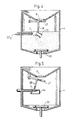
- The apparatus illustrated in Figure 1 comprises a casing 1 having pivotally mounted thereon a
lid 2, which serves as an operating device. The casing embraces agas tube 3 and aliquid container 4, which is connected to the gas tube via apipe 5. Liquid can be introduced into thecontainer 4 through anorifice 6. The liquid can be pressurized subsequent to the liquid reaching a level at which thenozzle 7 connected to thepipe 5 is surrounded by liquid. The liquid is pressurized by depressing thelid 2, which is, to this end, arranged to open avalve mechanism 9 connected to thegas container 3, via a peg 8. The peg 8 is embraced by aspring 10, which holds the lid in correct position when not activated. - The
filling orifice 6 is located in a funnel-shape part 11, which facilitates filling of the container with water and also prevents thecontainer 4 from being overfilled. Thus, a given volume ofair 12 will always be obtained above the surface of the liquid. Extending from this air-filledspace 12 is a gas-evacuating pipe 13, which leads to a combined over-pressure-and-evacuatingvalve 16. In the illustrated position, the valve body is pressed sealingly against the valve seat by means of onearm 17 of an angled lever, the other arm of which is referenced 18. Thearm 17 is pressed against the valve body by means of onearm 19 of a spring member, said spring member having asecond arm 20 which is mounted on avalve spindle 21. Thearms valve spindle 16 being acted upon by an upwardly directed force and thevalve 22 to be subjected to a downwardly acting tension force. Thereference 23 identifies a spring tongue, which is inactive in the illustrated position. Thetongue 23 is attached to ashaft 24, which can be rotated by means of alever 25. Theshaft 24 also carries an actuatingfinger 26. - The
filling orifice 6 is arranged to be closed by means of aflap valve 27, which is provided immediately in front of thenozzle 7 with an actuatingpart 28. Thereference 29 identifies an 0-ring surrounding theorifice 6. Thereference 30 identifies a plate on which a glass or the like can be placed when dispensing a drink. - The following steps are taken when charging carbon dioxide to the water and dispensing the aerated water into a glass by means of the aforedescribed apparatus. The
lid 2 is lifted and thecontainer 4 filled with water to a level above thenozzle 7. Thebottom valve 22 will be held closed by means of thespring arm 20. When the water reaches a selected level, thelid 2 is closed and depressed beyond the position shown in Figure 1. This will cause the valve of thegas container 3 to open, and a stream'-of carbon dioxide passes out through thenozzle 7. This stream or jet of carbon dioxide strikes the actuatingpart 28, which initiates a closing movement of theflap valve 27. Complete closure of the flap valve is effected as a result of the increasing pressure in thecontainer 4. - Thus, with this embodiment of the present invention no additional manual operations are required for closing the container, since the container is closed automatically in conjunction with charging carbon dioxide to the water. This embodiment also provides the advantage whereby the
valve 27 is normally open and a larger water-filling orifice can be used. When filling the container with water, the water is deflected to one side by theflap valve 27, which enables air in thecontainer 4 to readily escape therefrom, through the opposite side of the fillingorifice 6. - When the pressure of carbon dioxide in the
container 4 has reached a given value, thevalve 16 will open against the action of thespring arm 19. This can be announced by means of an acoustic signal, indicating that no more gas shall be charged, whereupon thelid 2 is released. When tapping water from the container, thelever arm 25 is swung clockwise, which forces the actuatingfinger 26 to open thevalve 16, at the same time as thespring tongue 23 strives to open theoutlet valve 22. In this respect, the force exerted by thespring tongue 23 is adapted in relation to the surface of thebottom valve 22, so that said bottom valve will not open until the pressure in the container has fallen to a given value, in response to the opening of thevalve 16. Thus, this means that no water can be fed from the container until the pressure therein is of such a low magnitude as to enable the water to be emptied with no problem. In this respect, theflap valve 27 is also re-opened, which enables the requisite amount of air to flow into the container to obtain trouble free dispensing of the water into a glass or the like, to which the desired flavouring substance can then be added and stirred into the water. - In the illustrated embodiment the filling
orifice 6 is closed in an extremely reliable and effective manner, due to the fact that the aforementioned closing movement is initiated by the jet or stream of carbon dioxide. - The aforedescribed apparatus is extremely simple to use, and enables the
gas container 3 to be readily changed, since all that is required in this respect is to release a snap-lock 31 at the bottom of thecontainer 4, whereafter the whole of the inner unit, comprising gas container and liquid container, can be lifted from the casing and the gas container changed. Thus, the change of gas containers can be readily effected without the use of tools. The aforedescribed apparatus is also of simple design and relatively cheap to produce. - Figure 2 illustrates schematically an alternative embodiment of the closure means arranged in the
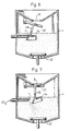
liquid container 4. For the sake of simplicity thebottom valve 22 has been illustrated schematically and the mechanism for evacuating gas and dispensing liquid from the container has not been shown in the Figure. This mechanism, however, may be identical with the mechanism illustrated in Figure 1. - The embodiment illustrated in Figure 2 is intended to eliminate those risks associated with the pressurizing of an empty
liquid container 4. - To this end, the
actuating arm 28 co-acting with thevalve 27 is provided at a location opposite the orifice ofnozzle 7 with an opening to which apipe section 33 is connected, the pipe section of the illustrated embodiment being shown to diverge. - If an attempt is made to pressurize the
container 4 before the level of liquid has reached thenozzle 7, the gas jet or stream will pass freely through thepipe 33 and will not initiate the aforementioned closing movement of thevalve 27. This is illustrated in Figure 3. - On the other hand, as illustrated in Figure 4, when the liquid container is filled with liquid to a level above the location of the
gas nozzle 7, thepipe section 33 will be filled with liquid. The gas jet will then act upon thearm 28, to initiate closing of thevalve 27. The valve is finally closed by the increasing gas pressure in thecontainer 4. - Figure 5 illustrates schematically an alternative embodiment of the liquid container. As with the former case, the
valve 27 cannot be closed until the level of liquid reaches thenozzle 7. In this respect, theactuating arm 28 has a lower part in the form of aninverted cup 34, the weight of said cup being such that the gas jet alone is unable to initiate the closing movement of said valve. When thecontainer 4 of the Figure 6 embodiment is filled with liquid, the air trapped in thecup 34 will provide a lifting force. This force, however, is too small to initiate closing of the valve. The weight and volume of thecup 34 are namely so selected that initiation of the said closing movement is not effected until the combination of liquid and gas jet is reached, see Figure 7. - Figure 8 illustrates another alternative embodiment of a means for closing the
valve 27. In this embodiment, theactuating arm 28 is connected to ahook 35 and abouyant body 37. When thecontainer 4 is empty, thehook 35 is in engagement with a corresponding means 36 on thegas nozzle 7, and thus prevents theactuating arm 28 from moving. When the level of liquid reaches thebouyant body 37, however, (see Figure 9) thehook 35 will be released from themember 36, whereafter closing of the valve can be initiated by means of the gas jet, as shown in Figure 10. - In all embodiments of the present invention further liquid can be supplied subsequent to the pre-determined level being reached, which is of decisive significance in enabling the beverage in question to be prepared in mutually different quantities.
Claims (7)
Priority Applications (1)
| Application Number | Priority Date | Filing Date | Title |
|---|---|---|---|
| AT83902460T ATE29475T1 (en) | 1982-07-16 | 1983-06-23 | DEVICE FOR SUPPLYING A GAS TO A LIQUID IN ITS CONTAINER. |
Applications Claiming Priority (2)
| Application Number | Priority Date | Filing Date | Title |
|---|---|---|---|
| SE8204368A SE431439B (en) | 1982-07-16 | 1982-07-16 | DEVICE FOR BATTLE GAS SETTING OF LIQUID IN A CONTAINER |
| SE8204368 | 1982-07-16 |
Publications (3)
| Publication Number | Publication Date |
|---|---|
| EP0128148A1 EP0128148A1 (en) | 1984-12-19 |
| EP0128148B1 EP0128148B1 (en) | 1987-09-09 |
| EP0128148B2 true EP0128148B2 (en) | 1990-10-10 |
Family
ID=20347398
Family Applications (1)
| Application Number | Title | Priority Date | Filing Date |
|---|---|---|---|
| EP83902460A Expired - Lifetime EP0128148B2 (en) | 1982-07-16 | 1983-06-23 | Apparatus for supplying gas to a liquid in a container therefor |
Country Status (8)
| Country | Link |
|---|---|
| US (1) | US4588536A (en) |
| EP (1) | EP0128148B2 (en) |
| AU (1) | AU552978B2 (en) |
| DE (1) | DE3373459D1 (en) |
| IT (2) | IT1162906B (en) |
| SE (1) | SE431439B (en) |
| WO (1) | WO1984000352A1 (en) |
| ZA (1) | ZA834725B (en) |
Families Citing this family (9)
| Publication number | Priority date | Publication date | Assignee | Title |
|---|---|---|---|---|
| US4660740A (en) * | 1986-02-18 | 1987-04-28 | The Sodamaster Company Of America | Gasification of fluids |
| US4850269A (en) * | 1987-06-26 | 1989-07-25 | Aquatec, Inc. | Low pressure, high efficiency carbonator and method |
| US5002201A (en) * | 1988-09-14 | 1991-03-26 | Aquatec Inc. | Bottled water cooler apparatus and method |
| SE512304C2 (en) * | 1998-04-22 | 2000-02-28 | Drinkit International Ab | Pressure container for batch gas liquefaction |
| WO2001010247A1 (en) * | 1999-08-04 | 2001-02-15 | Boluo Yaofeng Electronics Co. Ltd. | An inflation tube being able to stretch out and draw back |
| US20060162265A1 (en) * | 2005-01-13 | 2006-07-27 | Schield Edward L | Simulated window transom |
| GB2451635B (en) * | 2007-08-06 | 2012-03-28 | Diageo Great Britain Ltd | Apparatus for dispensing a carbonated beverage |
| US20200139312A1 (en) * | 2010-04-21 | 2020-05-07 | Tfb Consultants, Ltd | Gas Dispensing Method and Apparatus |
| US10384173B2 (en) * | 2010-04-21 | 2019-08-20 | TFB Consultants, Ltd. | Liquid decanting method and apparatus |
Family Cites Families (8)
| Publication number | Priority date | Publication date | Assignee | Title |
|---|---|---|---|---|
| US2647734A (en) * | 1951-03-14 | 1953-08-04 | Andrew J Nicholas | Household carbonator |
| US3248098A (en) * | 1962-11-15 | 1966-04-26 | Cornelius Co | Means of carbonating water |
| US3552726A (en) * | 1968-12-11 | 1971-01-05 | Eaton Yale & Towne | Motorless carbonator and method of operation |
| AT295309B (en) * | 1969-02-21 | 1971-12-27 | Imd | Device for making carbonated beverages |
| US3851797A (en) * | 1973-11-05 | 1974-12-03 | Gen Motors Corp | Portable dispenser apparatus for producing a carbonated beverage |
| SE427518B (en) * | 1978-08-02 | 1983-04-18 | Thorn Svenska Ab Kenwood | KIT AND APPARATUS FOR INTRODUCING A GAS INTO A LIQUID |
| GB2093359A (en) * | 1981-02-24 | 1982-09-02 | Thorn Cascade Co Ltd | Carbonated drinks machine |
| SE428678B (en) * | 1981-05-25 | 1983-07-18 | Aldolf Kb | DEVICE FOR BATTLE GAS SETTING OF LIQUID IN A CONTAINER |
-
1982
- 1982-07-16 SE SE8204368A patent/SE431439B/en not_active IP Right Cessation
-
1983
- 1983-06-23 EP EP83902460A patent/EP0128148B2/en not_active Expired - Lifetime
- 1983-06-23 AU AU17799/83A patent/AU552978B2/en not_active Ceased
- 1983-06-23 US US06/598,148 patent/US4588536A/en not_active Expired - Lifetime
- 1983-06-23 DE DE8383902460T patent/DE3373459D1/en not_active Expired
- 1983-06-23 WO PCT/SE1983/000261 patent/WO1984000352A1/en active IP Right Grant
- 1983-06-28 ZA ZA834725A patent/ZA834725B/en unknown
- 1983-07-15 IT IT67766/83A patent/IT1162906B/en active
- 1983-07-15 IT IT8353564U patent/IT8353564V0/en unknown
Also Published As
| Publication number | Publication date |
|---|---|
| SE8204368L (en) | 1984-01-17 |
| IT8353564V0 (en) | 1983-07-15 |
| AU1779983A (en) | 1984-02-08 |
| WO1984000352A1 (en) | 1984-02-02 |
| US4588536A (en) | 1986-05-13 |
| DE3373459D1 (en) | 1987-10-15 |
| IT1162906B (en) | 1987-04-01 |
| SE431439B (en) | 1984-02-06 |
| EP0128148A1 (en) | 1984-12-19 |
| SE8204368D0 (en) | 1982-07-16 |
| ZA834725B (en) | 1984-10-31 |
| EP0128148B1 (en) | 1987-09-09 |
| AU552978B2 (en) | 1986-06-26 |
| IT8367766A0 (en) | 1983-07-15 |
Similar Documents
| Publication | Publication Date | Title |
|---|---|---|
| EP0091904B1 (en) | An arrangement for supplying gas to a liquid in a container therefor | |
| US5044171A (en) | Counter with integral carbonated beverage dispenser | |
| US4940212A (en) | Compact carbonated beverage making system | |
| US4785974A (en) | System for serving a pre-mix beverage or making and serving a post-mix beverage in the zero gravity conditions of outer space | |
| EP1140692B1 (en) | Container for storing and dispensing beverage, in particular beer | |
| US5460846A (en) | Process and apparatus for rapidly carbonating a liquid beverage using a single pressure vessel | |
| EP0128148B2 (en) | Apparatus for supplying gas to a liquid in a container therefor | |
| US5947339A (en) | Beverage dispenser | |
| EP0383495A3 (en) | Home soda fountain dispensing system | |
| US10668437B2 (en) | Gas filling system | |
| US4709734A (en) | Method and system for filling packages with a carbonated beverage pre-mix under micro-gravity conditions | |
| US2912018A (en) | Aeration of liquids | |
| EP1080032B1 (en) | Pressure container for batch gasification of liquid | |
| EP0168990B1 (en) | Carbonating apparatus | |
| GB2089322A (en) | Method and means for dispensing a beverage | |
| US4892125A (en) | System for serving a pre-mix beverage or making and serving a post-mix beverage in the zero gravity conditions of outer space | |
| SU1716970A3 (en) | Microgravitation plant for dispensing carbonated or noncarbonated beverages under space conditions of microgravitation and metering device for microgravitation plant | |
| US2860819A (en) | Beverage dispensers | |
| JPH0555399B2 (en) | ||
| US1943217A (en) | Dispensing receptacle | |
| WO2000024650A1 (en) | Beverage container for a carbonated beverage | |
| US320751A (en) | Weeck | |
| JPH10258897A (en) | Feed valve for effervescent beverage | |
| SE428635B (en) | Arrangement for batchwise gassing of liquid in a container |
Legal Events
| Date | Code | Title | Description |
|---|---|---|---|
| PUAI | Public reference made under article 153(3) epc to a published international application that has entered the european phase |
Free format text: ORIGINAL CODE: 0009012 |
|
| 17P | Request for examination filed |
Effective date: 19840806 |
|
| AK | Designated contracting states |
Designated state(s): AT BE CH DE FR GB LI NL |
|
| GRAA | (expected) grant |
Free format text: ORIGINAL CODE: 0009210 |
|
| AK | Designated contracting states |
Kind code of ref document: B1 Designated state(s): AT BE CH DE FR GB LI NL |
|
| REF | Corresponds to: |
Ref document number: 29475 Country of ref document: AT Date of ref document: 19870915 Kind code of ref document: T |
|
| REF | Corresponds to: |
Ref document number: 3373459 Country of ref document: DE Date of ref document: 19871015 |
|
| ET | Fr: translation filed | ||
| PLBI | Opposition filed |
Free format text: ORIGINAL CODE: 0009260 |
|
| 26 | Opposition filed |
Opponent name: ISOWORTH LIMITED Effective date: 19880607 |
|
| NLR1 | Nl: opposition has been filed with the epo |
Opponent name: ISOWORTH LIMITED |
|
| RAP2 | Party data changed (patent owner data changed or rights of a patent transferred) |
Owner name: DRINK MAKER OF SWEDEN AB |
|
| NLT2 | Nl: modifications (of names), taken from the european patent patent bulletin |
Owner name: DRINK MAKER OF SWEDEN AB TE STRAENGNAES, ZWEDEN. |
|
| PUAH | Patent maintained in amended form |
Free format text: ORIGINAL CODE: 0009272 |
|
| STAA | Information on the status of an ep patent application or granted ep patent |
Free format text: STATUS: PATENT MAINTAINED AS AMENDED |
|
| 27A | Patent maintained in amended form |
Effective date: 19901010 |
|
| AK | Designated contracting states |
Kind code of ref document: B2 Designated state(s): AT BE CH DE FR GB LI NL |
|
| ET3 | Fr: translation filed ** decision concerning opposition | ||
| NLR2 | Nl: decision of opposition | ||
| NLR3 | Nl: receipt of modified translations in the netherlands language after an opposition procedure | ||
| REG | Reference to a national code |
Ref country code: CH Ref legal event code: PUE Owner name: DRINK MAKER OF SWEDEN AB |
|
| REG | Reference to a national code |
Ref country code: GB Ref legal event code: 732 |
|
| PGFP | Annual fee paid to national office [announced via postgrant information from national office to epo] |
Ref country code: DE Payment date: 20010118 Year of fee payment: 19 |
|
| PGFP | Annual fee paid to national office [announced via postgrant information from national office to epo] |
Ref country code: CH Payment date: 20010621 Year of fee payment: 19 Ref country code: AT Payment date: 20010621 Year of fee payment: 19 |
|
| PGFP | Annual fee paid to national office [announced via postgrant information from national office to epo] |
Ref country code: FR Payment date: 20010629 Year of fee payment: 19 |
|
| REG | Reference to a national code |
Ref country code: GB Ref legal event code: IF02 |
|
| PGFP | Annual fee paid to national office [announced via postgrant information from national office to epo] |
Ref country code: GB Payment date: 20020610 Year of fee payment: 20 |
|
| PGFP | Annual fee paid to national office [announced via postgrant information from national office to epo] |
Ref country code: BE Payment date: 20020617 Year of fee payment: 20 |
|
| PGFP | Annual fee paid to national office [announced via postgrant information from national office to epo] |
Ref country code: NL Payment date: 20020618 Year of fee payment: 20 |
|
| PG25 | Lapsed in a contracting state [announced via postgrant information from national office to epo] |
Ref country code: AT Free format text: LAPSE BECAUSE OF NON-PAYMENT OF DUE FEES Effective date: 20020623 |
|
| PG25 | Lapsed in a contracting state [announced via postgrant information from national office to epo] |
Ref country code: LI Free format text: LAPSE BECAUSE OF NON-PAYMENT OF DUE FEES Effective date: 20020630 Ref country code: CH Free format text: LAPSE BECAUSE OF NON-PAYMENT OF DUE FEES Effective date: 20020630 |
|
| PG25 | Lapsed in a contracting state [announced via postgrant information from national office to epo] |
Ref country code: DE Free format text: LAPSE BECAUSE OF NON-PAYMENT OF DUE FEES Effective date: 20030101 |
|
| REG | Reference to a national code |
Ref country code: CH Ref legal event code: PL |
|
| PG25 | Lapsed in a contracting state [announced via postgrant information from national office to epo] |
Ref country code: FR Free format text: LAPSE BECAUSE OF NON-PAYMENT OF DUE FEES Effective date: 20030228 |
|
| REG | Reference to a national code |
Ref country code: FR Ref legal event code: ST |
|
| PG25 | Lapsed in a contracting state [announced via postgrant information from national office to epo] |
Ref country code: GB Free format text: LAPSE BECAUSE OF EXPIRATION OF PROTECTION Effective date: 20030622 |
|
| PG25 | Lapsed in a contracting state [announced via postgrant information from national office to epo] |
Ref country code: NL Free format text: LAPSE BECAUSE OF EXPIRATION OF PROTECTION Effective date: 20030623 |
|
| BE20 | Be: patent expired |
Owner name: *DRINK MAKER OF SWEDEN A.B. Effective date: 20030623 |
|
| REG | Reference to a national code |
Ref country code: GB Ref legal event code: PE20 |
|
| NLV7 | Nl: ceased due to reaching the maximum lifetime of a patent |
Effective date: 20030623 |