EP0127562A2 - Bearing compartment protection system - Google Patents
Bearing compartment protection system Download PDFInfo
- Publication number
- EP0127562A2 EP0127562A2 EP84630070A EP84630070A EP0127562A2 EP 0127562 A2 EP0127562 A2 EP 0127562A2 EP 84630070 A EP84630070 A EP 84630070A EP 84630070 A EP84630070 A EP 84630070A EP 0127562 A2 EP0127562 A2 EP 0127562A2
- Authority
- EP
- European Patent Office
- Prior art keywords
- air
- buffer air
- engine
- bearing compartment
- buffer
- Prior art date
- Legal status (The legal status is an assumption and is not a legal conclusion. Google has not performed a legal analysis and makes no representation as to the accuracy of the status listed.)
- Granted
Links
Images

Classifications
-
- F—MECHANICAL ENGINEERING; LIGHTING; HEATING; WEAPONS; BLASTING
- F01—MACHINES OR ENGINES IN GENERAL; ENGINE PLANTS IN GENERAL; STEAM ENGINES
- F01D—NON-POSITIVE DISPLACEMENT MACHINES OR ENGINES, e.g. STEAM TURBINES
- F01D25/00—Component parts, details, or accessories, not provided for in, or of interest apart from, other groups
- F01D25/18—Lubricating arrangements
- F01D25/183—Sealing means
-
- F—MECHANICAL ENGINEERING; LIGHTING; HEATING; WEAPONS; BLASTING
- F01—MACHINES OR ENGINES IN GENERAL; ENGINE PLANTS IN GENERAL; STEAM ENGINES
- F01D—NON-POSITIVE DISPLACEMENT MACHINES OR ENGINES, e.g. STEAM TURBINES
- F01D11/00—Preventing or minimising internal leakage of working-fluid, e.g. between stages
-
- F—MECHANICAL ENGINEERING; LIGHTING; HEATING; WEAPONS; BLASTING
- F01—MACHINES OR ENGINES IN GENERAL; ENGINE PLANTS IN GENERAL; STEAM ENGINES
- F01D—NON-POSITIVE DISPLACEMENT MACHINES OR ENGINES, e.g. STEAM TURBINES
- F01D25/00—Component parts, details, or accessories, not provided for in, or of interest apart from, other groups
- F01D25/08—Cooling; Heating; Heat-insulation
- F01D25/12—Cooling
- F01D25/125—Cooling of bearings
-
- F—MECHANICAL ENGINEERING; LIGHTING; HEATING; WEAPONS; BLASTING
- F02—COMBUSTION ENGINES; HOT-GAS OR COMBUSTION-PRODUCT ENGINE PLANTS
- F02C—GAS-TURBINE PLANTS; AIR INTAKES FOR JET-PROPULSION PLANTS; CONTROLLING FUEL SUPPLY IN AIR-BREATHING JET-PROPULSION PLANTS
- F02C7/00—Features, components parts, details or accessories, not provided for in, or of interest apart form groups F02C1/00 - F02C6/00; Air intakes for jet-propulsion plants
- F02C7/12—Cooling of plants
- F02C7/16—Cooling of plants characterised by cooling medium
- F02C7/18—Cooling of plants characterised by cooling medium the medium being gaseous, e.g. air
- F02C7/185—Cooling means for reducing the temperature of the cooling air or gas
-
- F—MECHANICAL ENGINEERING; LIGHTING; HEATING; WEAPONS; BLASTING
- F16—ENGINEERING ELEMENTS AND UNITS; GENERAL MEASURES FOR PRODUCING AND MAINTAINING EFFECTIVE FUNCTIONING OF MACHINES OR INSTALLATIONS; THERMAL INSULATION IN GENERAL
- F16C—SHAFTS; FLEXIBLE SHAFTS; ELEMENTS OR CRANKSHAFT MECHANISMS; ROTARY BODIES OTHER THAN GEARING ELEMENTS; BEARINGS
- F16C27/00—Elastic or yielding bearings or bearing supports, for exclusively rotary movement
- F16C27/04—Ball or roller bearings, e.g. with resilient rolling bodies
- F16C27/045—Ball or roller bearings, e.g. with resilient rolling bodies with a fluid film, e.g. squeeze film damping
-
- F—MECHANICAL ENGINEERING; LIGHTING; HEATING; WEAPONS; BLASTING
- F16—ENGINEERING ELEMENTS AND UNITS; GENERAL MEASURES FOR PRODUCING AND MAINTAINING EFFECTIVE FUNCTIONING OF MACHINES OR INSTALLATIONS; THERMAL INSULATION IN GENERAL
- F16C—SHAFTS; FLEXIBLE SHAFTS; ELEMENTS OR CRANKSHAFT MECHANISMS; ROTARY BODIES OTHER THAN GEARING ELEMENTS; BEARINGS
- F16C19/00—Bearings with rolling contact, for exclusively rotary movement
- F16C19/22—Bearings with rolling contact, for exclusively rotary movement with bearing rollers essentially of the same size in one or more circular rows, e.g. needle bearings
- F16C19/24—Bearings with rolling contact, for exclusively rotary movement with bearing rollers essentially of the same size in one or more circular rows, e.g. needle bearings for radial load mainly
- F16C19/26—Bearings with rolling contact, for exclusively rotary movement with bearing rollers essentially of the same size in one or more circular rows, e.g. needle bearings for radial load mainly with a single row of rollers
-
- F—MECHANICAL ENGINEERING; LIGHTING; HEATING; WEAPONS; BLASTING
- F16—ENGINEERING ELEMENTS AND UNITS; GENERAL MEASURES FOR PRODUCING AND MAINTAINING EFFECTIVE FUNCTIONING OF MACHINES OR INSTALLATIONS; THERMAL INSULATION IN GENERAL
- F16C—SHAFTS; FLEXIBLE SHAFTS; ELEMENTS OR CRANKSHAFT MECHANISMS; ROTARY BODIES OTHER THAN GEARING ELEMENTS; BEARINGS
- F16C2360/00—Engines or pumps
- F16C2360/23—Gas turbine engines
-
- Y—GENERAL TAGGING OF NEW TECHNOLOGICAL DEVELOPMENTS; GENERAL TAGGING OF CROSS-SECTIONAL TECHNOLOGIES SPANNING OVER SEVERAL SECTIONS OF THE IPC; TECHNICAL SUBJECTS COVERED BY FORMER USPC CROSS-REFERENCE ART COLLECTIONS [XRACs] AND DIGESTS
- Y02—TECHNOLOGIES OR APPLICATIONS FOR MITIGATION OR ADAPTATION AGAINST CLIMATE CHANGE
- Y02T—CLIMATE CHANGE MITIGATION TECHNOLOGIES RELATED TO TRANSPORTATION
- Y02T50/00—Aeronautics or air transport
- Y02T50/60—Efficient propulsion technologies, e.g. for aircraft
Definitions
- This invention relates to gas turbine power plants for powering aircraft and particularly to means for buffering the bearings mounted in proximity to the hot section of the power plant.
- This invention serves to solve the particular problem enumerated above by providing a high pressure, cooler air buffer zone for a bearing that is encapsulated adjacent to the combustion section.
- a high pressure, cooler air buffer zone for a bearing that is encapsulated adjacent to the combustion section.
- the buffer zone is defined by an elongated annular space defined between the rotating shaft and a stationary annular, radially spaced, parallelly disposed extension number. This member being open ended so that flow admitted to said buffer zone intermediate the ends thereof flows axially in either direction with a preference of flowing toward the radial seal disposed on one of said ends.
- the buffer zone is fed by at least one pipe (preferably two) for each of the buffer zones associated with the pair of carbon seals.
- the bearing compartment is shrouded defining an annular passage feeding the buffer zone, which passage cools the entire bearing compartment surface.
- the second outer shroud forms a heat shield by surrounding the annular passage and is dead-ended to provide an insulation of dead air.
- the air bled from the compressor to buffer the bearing compartment is utilized downstream of the engine in a manner that will not adversely penalize the engine's performance.
- An object of this invention is to provide for a gas turbine engine, means for buffering the bearing compartment so as to insulate this compartment from the hotter environment in close proximity thereto.
- a feature of this invention is to supply high pressure air from the compressor after first passing said air through a heat exchanger to cool the air to surround the bearing compartment seals.
- a feature of this invention is the open ended buffer zone adjacent the bearing compartment seals that admit both buffer air and environment air into the compartment in the event of a seal malfunction which air does not adversely affect the bearing and its components. Another feature is achieving temperature buffering without the use of labyrinth seals and the adverse conditions associated with the use of seals.
- a still further feature of this invention is to utilize the high pressure, cooler buffer air to cool the high pressure turbine resulting in an effective use of compressor air utilized for cooling purposes without incurring an engine operating penalty.
- Figs. 1 & 2 showing a typical fan jet engine generally indicated by reference numeral 10, having a fan section, compressor section, combustor section, turbine section and exhaust section.
- reference numeral 10 For the sake of simplicity and convenience, the details of a suitable gas turbine engine is omitted herefrom but reference should be made to the JT-9D engine manufactured by Pratt & Whitney Aircraft of United Technologies Corporation, the assignee of this patent application.
- the power plant comprises a twin spool having axial flow compressor and turbine stages, where each set of stages of the compressor and turbines are interconnected by a shaft.
- the burner section is disposed between the compressor and turbine sections for developing sufficient energy to power the turbine and develop thrust for propulsion.
- the high pressure spool or gas generator (not shown) consists of shaft 12 suitably supported by roller bearings generally indicated by reference numeral 14. These bearings are well known and consists of an inner ring 16 mounted adjacent shaft 12, an outer ring 18, a plurality of rollers 20 and cage 22 and, in this instant, are surrounded by fluid damper 26.
- the bearing is encapsulated in the cavity or compartment 38 defined by housing 36 surrounding the shaft 12.
- the ends of the compartment 38 are sealed by suitable carbon seals 40 and 40' which are spring loaded (not shown) against the face of the seal plates 42 and 42' respectively.
- the construction of the carbon seals are well known and an example of a suitable construction is shown in U.S. Patent No. 2,992,842 granted to Shevchenko et al on July 18, 1961 also assigned to the same assignee as this patent application and incorporated herein by reference.
- the cavity 38 is continuously subjected to the flow of oil which serves to lubricate and cool the bearings which oil is returned through return line 44 mounted on the bottom of housing 36.
- the bearing housing is supported to the diffuser case partially shown as reference numeral 46 which surrounds the burner line (not shown) and defines therewith a cavity 48 that surrounds and shrouds the burner liner. Since the bearing compartment is radially disposed relative to the combustor and is exposed to the already heated compressor discharge air surrounding the bearing compartment, under certain operating conditions this location of the engine has the propensity of becoming extremely hot.
- One method of insulating the bearing cavity 38 from this excessive heat is by wrapping an insulating blanket 50 of suitable material (partially shown) around the housing 36.
- a buffer zone is disposed at the inside diameter of the carbon seals.
- This buffer zone is supplied with a cool,high pressure air bled from the compressor. The temperature of this air is cooler and at a higher pressure than the ambient air surrounding the bearing compartment. While this system prevents hot air from entering the bearing compartment under normal operating conditions, in the event of an inadvertent leakage of the seal, the hotter ambient air is likewise prevented from entering into the bearing compartment, without first being mixed with buffer air.
- the cooler pressurized air is introduced at the inner diameter of the carbon seal in the annulus 48 and 48' by pipes 60 and 62 to fill the spaces between the shaft 12, seal support structure 52 up to the seal plate 42 on the left hand side of the bearing 14 and between the sleeve 56, seal support 52' up to the seal plate 42', on the right hand side of bearing 14. While only a single feed line is shown on either side of the bearing, each side may carry more than one pipe, and two pipes spaced 180 0 apart are preferred in this embodiment.
- Pipes 60 and 62 are concentrically mounted in outer tubes 66 & 64, respectively, which serve to insulate the inner pipe and maintain the air flowing to the buffer zone at a proper temperature level.
- the cooler pressurized air as can be seen from Fig. 1, is bled from a suitable station in the compressor section, routed outside of the engine via line 68, through the fan heat exchanger 70 and returned internally via line 69 to the pipes 60 and 62 through manifold 72, (Fig. 2).
- the air feeding the buffer zone 48 and 48' which virtually is an annular chamber surrounding the shaft that feeds the leakage path across the carbon seals 40 and 40' is introduced at a point that is remote from the carbon seals.
- cavities 48 and 48' are both open ended chambers where buffer air can flow out through the carbon seal or through the gaps 80 and 80'.
- some portion of this air will always flow toward the carbon seal while the remaining portion of this air flows out of the buffer zone 48 and 48' through the gaps 80 and 80'.
- the amount of air required by a carbon seal is minimal relative to that supplied to the buffer zone during normal operation. The excess flow flows out gap 80.
- Fig. 3 exemplifies another embodiment of this invention and like-reference numerals refer to like parts.
- the encapsulated bearing compartment is enclosed on virtually both the left and right hand sides with sheet metal sheaths 86 and 86' spaced therefrom to define annular chambers 88 and 88'.
- a second left and right hand side sheath 90 and 90' encapsulate the entire unit and is spaced from the inner sheath 86 and 86' to define annular spaces 92 and 92'.
- the outer annular spaces 92 and 92' are dead ended and provide a dead air space that serve as an insulating blanket for the bearing compartment. This minimizes heat transfer from the hotter air surrounding the compartment to the oil in the bearing compartment.
- the system in Fig. 3 receives the higher pressure, cooler air from the heat exchanger and is fed into conduit 96 that serves as a manifold to feed the annular spaces 88 and 88' which in turn feeds the buffer zones 48 and 48'.
- the buffer zones are open-ended and do not require closely held labyrinth seals to contain the buffer air and prevent hot environmental air pollution in close proximity of the carbon seals.
- the system can be satisfied with the proper pressure, and temperature air.
- the buffer air temperature is colder for a given pressure level than air directly drawn off the compressor system.
Abstract
Description
- This invention relates to gas turbine power plants for powering aircraft and particularly to means for buffering the bearings mounted in proximity to the hot section of the power plant.
- In recent years, the industry has been undertaking an intensive effort in designing, developing and manufacturing power plants that exhibited a high thrust specific fuel consumption (TSFC). To this end it is desirous to operate the engine during at least a portion of its operating envelope at a temperature higher than has heretofore been achieved. One of the consequences of these "hotter" engines is that the mid-frame bearings supporting the rotating machinery is disposed in a hotter and higher pressure environment than has heretofore been encountered.
- Coincidental with disposing the bearings in a hotter environment, outside bearing compartment pressures have risen attendantly. The consequences of these conditions, namely hotter and higher pressure environment and pressurized bearing compartment could result in an undesirable condition with the bearing compartment, which may manifest in fires and degradation of the components.
- While the industry has provided buffer means for bearings in heretofore known engines, such systems flow air at a lower temperature and much lower pressure and/or cooler air at the same pressure into a cavity surrounding the bearing or in close proximity thereto. For such heretofore known systems to work satisfactorily it is necessary to continuously flow the air to lower pressure areas of the engine in order to generate sufficiently lower pressure at the seal adjacent the bearing compartment. In some installations it was also necessary to vent the excess flow overboard. Whether that air is being vented overboard or routed to a lower pressure area, by bypassing the high pressure turbine, the use of the air in this manner results in an overall loss in engine performance. To obtain the proper pressure in these heretofore designs it is necessary to create a pressure drop by the use of seals and in practice these seals are typically of the labyrinth design. Obviously, the constant wear of these seals adversely affect the pressure drop valve and hence flow.
- - Thus, these heretofore known systems incur disadvantages requiring a substantial amount of air to buffer the external surfaces of the bearing compartment and discharging the buffer air to lower engine pressures or overboard and requiring pressure reducing seals.
- This invention serves to solve the particular problem enumerated above by providing a high pressure, cooler air buffer zone for a bearing that is encapsulated adjacent to the combustion section. We have found that we can obtain a satisfactory environment that minimizes the likelihood of inadvertent fires in the area of the bearings by applying adjacent to the seals of the bearing compartment high pressure compressor air that has been cooled to some temperature below the flash point of the oil/air mixture associated with the bearing cooling and lubrication system. The pressure of the buffer air is slightly higher than the hotter ambient air so that the hotter air will not migrate to the bearing compartment in the event of the seal malfunctioning. It is contemplated that the cooled compressor bleed air is fed to a buffer zone formed adjacent to the carbon seals of the bearing compartment. The buffer zone is defined by an elongated annular space defined between the rotating shaft and a stationary annular, radially spaced, parallelly disposed extension number. This member being open ended so that flow admitted to said buffer zone intermediate the ends thereof flows axially in either direction with a preference of flowing toward the radial seal disposed on one of said ends.
- In one of the preferred embodiments the buffer zone is fed by at least one pipe (preferably two) for each of the buffer zones associated with the pair of carbon seals. In another embodiment the bearing compartment is shrouded defining an annular passage feeding the buffer zone, which passage cools the entire bearing compartment surface. The second outer shroud forms a heat shield by surrounding the annular passage and is dead-ended to provide an insulation of dead air.
- It is contemplated by this invention that the air bled from the compressor to buffer the bearing compartment is utilized downstream of the engine in a manner that will not adversely penalize the engine's performance.
- Notwithstanding the fact that the compressor air routed to the bearing compartment has been heated to some degree in its contact with the combustor environment, the air still is sufficiently cool to be useful in cooling the hot high turbine rotor. And since the pressure of this air is sufficiently high to be compatible with the pressure in the high turbine environment, it is routed there to scrub this hot section. In engines that employ tangential on board injectors (TOBI) for cooling the high turbine rotor, the advantages of utilizing this invention results in utilizing less TOBI air than would otherwise be necessary. It is possible, because of the relative low temperature of the air from the buffer to the TOBI air, a significant savings in the use of the overall cooling air for the high pressure turbine may be realized. For a complete description of a TOBI reference should be made to U.S. Patent No. 3,768,921 granted to W. M. Brown and W. A. Grace on October 30, 1973 and assigned to the same assignee as this patent application.
- An object of this invention is to provide for a gas turbine engine, means for buffering the bearing compartment so as to insulate this compartment from the hotter environment in close proximity thereto. A feature of this invention is to supply high pressure air from the compressor after first passing said air through a heat exchanger to cool the air to surround the bearing compartment seals. A feature of this invention is the open ended buffer zone adjacent the bearing compartment seals that admit both buffer air and environment air into the compartment in the event of a seal malfunction which air does not adversely affect the bearing and its components. Another feature is achieving temperature buffering without the use of labyrinth seals and the adverse conditions associated with the use of seals.
- The higher pressure buffer air overflows relative to the needs of the compartment carbon seals, precluding the hot surrounding air from entering the carbon seal leakage. Since the knife edge labyrinth seals are no longer necessary, whose clearance increases upon engine operation, the buffering system becomes insensitive to seal rubs and therefore effectuates a greater degree of safety against fires which would otherwise occur due to normal engine operation deterioration.
- A still further feature of this invention is to utilize the high pressure, cooler buffer air to cool the high pressure turbine resulting in an effective use of compressor air utilized for cooling purposes without incurring an engine operating penalty.
- Other features and advantages will be apparent from the specification and claims and from the accompanying drawings which illustrate an embodiment of the invention.
-
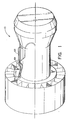
- Fig. 1 is a schematic and perspective of a gas turbine engine with the heat exchanger utilized to cool the compressor air prior to being returned as the buffer air, and
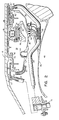
- - Fig. 2 is a fragmentary view partly in section and partly in schematic showing a first embodiment of this invention.
- Fig. 3 is a fragmentary view partly in section and partly in schematic showing another embodiment of this invention.
- The invention can best be understood by referring to Figs. 1 & 2, showing a typical fan jet engine generally indicated by
reference numeral 10, having a fan section, compressor section, combustor section, turbine section and exhaust section. For the sake of simplicity and convenience, the details of a suitable gas turbine engine is omitted herefrom but reference should be made to the JT-9D engine manufactured by Pratt & Whitney Aircraft of United Technologies Corporation, the assignee of this patent application. - Suffice it to say that the power plant comprises a twin spool having axial flow compressor and turbine stages, where each set of stages of the compressor and turbines are interconnected by a shaft. The burner section is disposed between the compressor and turbine sections for developing sufficient energy to power the turbine and develop thrust for propulsion. As noted in more detail in Fig. 2, the high pressure spool or gas generator (not shown) consists of
shaft 12 suitably supported by roller bearings generally indicated byreference numeral 14. These bearings are well known and consists of aninner ring 16 mountedadjacent shaft 12, anouter ring 18, a plurality ofrollers 20 andcage 22 and, in this instant, are surrounded byfluid damper 26. The damper and bearing are, in turn, supported and grounded to theannular support member 30 which is supported between flanges 32 & 34 of thebearing case 36 and 36'. Bearingcase 36 & 36' encapsulates thebearing 14. For more details of a bearing and fluid damper construction reference should be made to U.S. Patent No. 4,337,983 granted to D. H. Hibner on July 6, 1983 and U.S. Patent No. 4,385,788 granted to P. F. Brown, Jr. et al on May 31, 1983, both of which are assigned to the same assignee as this patent application and which are both incorporated herein by reference. - As is apparent from the foregoing the bearing is encapsulated in the cavity or
compartment 38 defined byhousing 36 surrounding theshaft 12. The ends of thecompartment 38 are sealed bysuitable carbon seals 40 and 40' which are spring loaded (not shown) against the face of theseal plates 42 and 42' respectively. The construction of the carbon seals are well known and an example of a suitable construction is shown in U.S. Patent No. 2,992,842 granted to Shevchenko et al on July 18, 1961 also assigned to the same assignee as this patent application and incorporated herein by reference. - As is well known, the
cavity 38 is continuously subjected to the flow of oil which serves to lubricate and cool the bearings which oil is returned throughreturn line 44 mounted on the bottom ofhousing 36. - In this installation the bearing housing is supported to the diffuser case partially shown as
reference numeral 46 which surrounds the burner line (not shown) and defines therewith acavity 48 that surrounds and shrouds the burner liner. Since the bearing compartment is radially disposed relative to the combustor and is exposed to the already heated compressor discharge air surrounding the bearing compartment, under certain operating conditions this location of the engine has the propensity of becoming extremely hot. - One method of insulating the
bearing cavity 38 from this excessive heat is by wrapping aninsulating blanket 50 of suitable material (partially shown) around thehousing 36. - In addition thereto or as an alternate to the insulation system a buffer zone is disposed at the inside diameter of the carbon seals. This buffer zone is supplied with a cool,high pressure air bled from the compressor. The temperature of this air is cooler and at a higher pressure than the ambient air surrounding the bearing compartment. While this system prevents hot air from entering the bearing compartment under normal operating conditions, in the event of an inadvertent leakage of the seal, the hotter ambient air is likewise prevented from entering into the bearing compartment, without first being mixed with buffer air. In the embodiment shown in Fig. 2, the cooler pressurized air is introduced at the inner diameter of the carbon seal in the
annulus 48 and 48' bypipes 60 and 62 to fill the spaces between theshaft 12, seal support structure 52 up to theseal plate 42 on the left hand side of thebearing 14 and between thesleeve 56, seal support 52' up to the seal plate 42', on the right hand side of bearing 14. While only a single feed line is shown on either side of the bearing, each side may carry more than one pipe, and two pipes spaced 1800 apart are preferred in this embodiment. -
Pipes 60 and 62 are concentrically mounted in outer tubes 66 & 64, respectively, which serve to insulate the inner pipe and maintain the air flowing to the buffer zone at a proper temperature level. The cooler pressurized air, as can be seen from Fig. 1, is bled from a suitable station in the compressor section, routed outside of the engine vialine 68, through thefan heat exchanger 70 and returned internally vialine 69 to thepipes 60 and 62 throughmanifold 72, (Fig. 2). - As noted from Fig. 2, the air feeding the
buffer zone 48 and 48' which virtually is an annular chamber surrounding the shaft that feeds the leakage path across the carbon seals 40 and 40' is introduced at a point that is remote from the carbon seals. It will be appreciated thatcavities 48 and 48' are both open ended chambers where buffer air can flow out through the carbon seal or through thegaps 80 and 80'. However because of the proper selection of the pressure of buffer air some portion of this air will always flow toward the carbon seal while the remaining portion of this air flows out of thebuffer zone 48 and 48' through thegaps 80 and 80'. The amount of air required by a carbon seal is minimal relative to that supplied to the buffer zone during normal operation. The excess flow flows outgap 80. Under abnormal seal "stuck" or failure of the carbon seal, the total buffer flow and possibly some hot environmental air would leak into the compartment without major fire and possibly catastrophic failure consequences. The excess air under normal operation is used to supply air to the high turbine blades. The blades are not over serviced because 1) air normally used say, through the TOBI, to service blades has been reduced and 2) further reduction of this TOBI air is possible because excess air from the buffer zone is cooler. By virtue of this invention a performance benefit is realized. - Fig. 3 exemplifies another embodiment of this invention and like-reference numerals refer to like parts. In this embodiment the encapsulated bearing compartment is enclosed on virtually both the left and right hand sides with
sheet metal sheaths 86 and 86' spaced therefrom to defineannular chambers 88 and 88'. A second left and righthand side sheath 90 and 90' encapsulate the entire unit and is spaced from theinner sheath 86 and 86' to defineannular spaces 92 and 92'. The outerannular spaces 92 and 92' are dead ended and provide a dead air space that serve as an insulating blanket for the bearing compartment. This minimizes heat transfer from the hotter air surrounding the compartment to the oil in the bearing compartment. - As was the case of the system in Fig. 2, the system in Fig. 3 receives the higher pressure, cooler air from the heat exchanger and is fed into
conduit 96 that serves as a manifold to feed theannular spaces 88 and 88' which in turn feeds thebuffer zones 48 and 48'. Also, like the system in Fig. 2, the buffer zones are open-ended and do not require closely held labyrinth seals to contain the buffer air and prevent hot environmental air pollution in close proximity of the carbon seals. - By maintaining the pressure at the buffer zone at a higher value than the ambient air surrounding the encapsulated bearing compartment, leakage of the hotter environmental air into the bearing ccmpartment is thwarted by the higher pressure cooler air in the buffer zone. This, obviously, negates the possibility of the oil in the bearing compartment mixing with the hotter air, which could result in an adverse condition.
- By utilizing some of the high pressure air, for example, the air at the discharge end of the compressor, and then cooling that air prior to being admitted into the buffer zone, the system can be satisfied with the proper pressure, and temperature air.
- In addition to the advantage of using a small amount of bleed air which contrasts from heretofore buffer systems that continuously feed cooler air (not pressurized) and relies on the quantity flowing over the bearing for maintaining the cooling and buffering effort, this system affords other advantages, though not limited thereto.
- It reduces the potential for bearing compartment fires by reducing the carbon seal leakage air temperature significantly.
- It provides cold air at high pressures to buffer the compartment; the buffer air temperature is colder for a given pressure level than air directly drawn off the compressor system.
- It increases the compartment environment pressure at which you can safely operate the bearing compartment.
- In the event of a carbon seal failure, there is sufficient cold buffer air supplied to prevent a compartment oil fire.
- Under normal operating conditions the excess buffer flow can be used to cool the high pressure turbine blades. This cooler air reduces the flow requirements needed from other sources as from the TOBI and augments the performance benefits.
- It should be understood that the invention is not limited to the particular embodiments shown and described herein, but that various changes and modifications may be made without departing from the spirit and scope of this novel concept as defined by the following claims.
Claims (6)
Applications Claiming Priority (2)
| Application Number | Priority Date | Filing Date | Title |
|---|---|---|---|
| US49963383A | 1983-05-31 | 1983-05-31 | |
| US499633 | 1983-05-31 |
Publications (3)
| Publication Number | Publication Date |
|---|---|
| EP0127562A2 true EP0127562A2 (en) | 1984-12-05 |
| EP0127562A3 EP0127562A3 (en) | 1987-04-08 |
| EP0127562B1 EP0127562B1 (en) | 1990-08-08 |
Family
ID=23986059
Family Applications (1)
| Application Number | Title | Priority Date | Filing Date |
|---|---|---|---|
| EP84630070A Expired - Lifetime EP0127562B1 (en) | 1983-05-31 | 1984-04-27 | Bearing compartment protection system |
Country Status (3)
| Country | Link |
|---|---|
| EP (1) | EP0127562B1 (en) |
| JP (1) | JPS59226236A (en) |
| DE (2) | DE127562T1 (en) |
Cited By (7)
| Publication number | Priority date | Publication date | Assignee | Title |
|---|---|---|---|---|
| WO1995031632A1 (en) * | 1994-05-17 | 1995-11-23 | Pratt & Whitney Canada Inc. | Annular bearing compartment |
| WO2001027444A1 (en) * | 1999-10-12 | 2001-04-19 | Alm Development, Inc. | Bearing housing for a turbomachine |
| FR2961258A1 (en) * | 2010-06-15 | 2011-12-16 | Snecma | CARBON SEALING AND SEALING DEVICE WITH INTEGRATED SMOOTH BEARING FOR A TURBOMACHINE |
| US8689561B2 (en) | 2009-09-13 | 2014-04-08 | Donald W. Kendrick | Vortex premixer for combustion apparatus |
| EP2809907A4 (en) * | 2012-01-31 | 2015-10-28 | United Technologies Corp | Buffer system for a gas turbine engine |
| WO2019162600A1 (en) * | 2018-02-23 | 2019-08-29 | Safran Aircraft Engines | Turbine engine comprising a heat exchanger consisting of at least one deck between vanes |
| CN114542205A (en) * | 2022-02-11 | 2022-05-27 | 中国航发沈阳发动机研究所 | High-temperature-resistant and high-pressure-resistant bearing cavity structure of high-mach aircraft engine |
Families Citing this family (3)
| Publication number | Priority date | Publication date | Assignee | Title |
|---|---|---|---|---|
| US6799112B1 (en) * | 2003-10-03 | 2004-09-28 | General Electric Company | Methods and apparatus for operating gas turbine engines |
| FR2877036B1 (en) * | 2004-10-27 | 2006-12-22 | Snecma Moteurs Sa | DEVICE FOR LUBRICATING A COMPONENT IN A TURBOMACHINE |
| US10167734B2 (en) | 2012-09-27 | 2019-01-01 | United Technologies Corporation | Buffer airflow to bearing compartment |
Citations (11)
| Publication number | Priority date | Publication date | Assignee | Title |
|---|---|---|---|---|
| CH266730A (en) * | 1948-08-11 | 1950-02-15 | Siegfried Keller & Co | Device to avoid loss of lubricant in high-speed turbo machines with a flying rotor arrangement. |
| US2749087A (en) * | 1951-04-18 | 1956-06-05 | Bristol Aeroplane Co Ltd | Rotary machines |
| US2791090A (en) * | 1952-08-05 | 1957-05-07 | Bristol Aeroplane Co Ltd | Improved cooling and lubricating arrangement for bearings of a gas turbine engine |
| US2992842A (en) * | 1958-04-21 | 1961-07-18 | United Aircraft Corp | Oil scrubbed face seal |
| FR1484834A (en) * | 1966-05-09 | 1967-06-16 | Bristol Siddeley Engines Ltd | Improvements to engines incorporating a gas turbine |
| US3768921A (en) * | 1972-02-24 | 1973-10-30 | Aircraft Corp | Chamber pressure control using free vortex flow |
| FR2205627A1 (en) * | 1972-11-08 | 1974-05-31 | Bbc Sulzer Turbomaschinen | |
| US4156342A (en) * | 1976-06-11 | 1979-05-29 | Westinghouse Canada Limited | Cooling apparatus for a bearing in a gas turbine |
| US4337983A (en) * | 1980-12-11 | 1982-07-06 | United Technologies Corporation | Viscous damper |
| US4369016A (en) * | 1979-12-21 | 1983-01-18 | United Technologies Corporation | Turbine intermediate case |
| US4385788A (en) * | 1981-06-26 | 1983-05-31 | United Technologies Corporation | Roller bearing and construction thereof |
Family Cites Families (2)
| Publication number | Priority date | Publication date | Assignee | Title |
|---|---|---|---|---|
| GB1421540A (en) * | 1972-11-24 | 1976-01-21 | Rolls Royce | Shaft bearing assemblies |
| US3844110A (en) * | 1973-02-26 | 1974-10-29 | Gen Electric | Gas turbine engine internal lubricant sump venting and pressurization system |
-
1984
- 1984-04-27 DE DE198484630070T patent/DE127562T1/en active Pending
- 1984-04-27 EP EP84630070A patent/EP0127562B1/en not_active Expired - Lifetime
- 1984-04-27 JP JP59086082A patent/JPS59226236A/en active Granted
- 1984-04-27 DE DE8484630070T patent/DE3482915D1/en not_active Expired - Fee Related
Patent Citations (11)
| Publication number | Priority date | Publication date | Assignee | Title |
|---|---|---|---|---|
| CH266730A (en) * | 1948-08-11 | 1950-02-15 | Siegfried Keller & Co | Device to avoid loss of lubricant in high-speed turbo machines with a flying rotor arrangement. |
| US2749087A (en) * | 1951-04-18 | 1956-06-05 | Bristol Aeroplane Co Ltd | Rotary machines |
| US2791090A (en) * | 1952-08-05 | 1957-05-07 | Bristol Aeroplane Co Ltd | Improved cooling and lubricating arrangement for bearings of a gas turbine engine |
| US2992842A (en) * | 1958-04-21 | 1961-07-18 | United Aircraft Corp | Oil scrubbed face seal |
| FR1484834A (en) * | 1966-05-09 | 1967-06-16 | Bristol Siddeley Engines Ltd | Improvements to engines incorporating a gas turbine |
| US3768921A (en) * | 1972-02-24 | 1973-10-30 | Aircraft Corp | Chamber pressure control using free vortex flow |
| FR2205627A1 (en) * | 1972-11-08 | 1974-05-31 | Bbc Sulzer Turbomaschinen | |
| US4156342A (en) * | 1976-06-11 | 1979-05-29 | Westinghouse Canada Limited | Cooling apparatus for a bearing in a gas turbine |
| US4369016A (en) * | 1979-12-21 | 1983-01-18 | United Technologies Corporation | Turbine intermediate case |
| US4337983A (en) * | 1980-12-11 | 1982-07-06 | United Technologies Corporation | Viscous damper |
| US4385788A (en) * | 1981-06-26 | 1983-05-31 | United Technologies Corporation | Roller bearing and construction thereof |
Cited By (15)
| Publication number | Priority date | Publication date | Assignee | Title |
|---|---|---|---|---|
| WO1995031632A1 (en) * | 1994-05-17 | 1995-11-23 | Pratt & Whitney Canada Inc. | Annular bearing compartment |
| WO2001027444A1 (en) * | 1999-10-12 | 2001-04-19 | Alm Development, Inc. | Bearing housing for a turbomachine |
| US8689561B2 (en) | 2009-09-13 | 2014-04-08 | Donald W. Kendrick | Vortex premixer for combustion apparatus |
| US8689562B2 (en) | 2009-09-13 | 2014-04-08 | Donald W. Kendrick | Combustion cavity layouts for fuel staging in trapped vortex combustors |
| US8920034B2 (en) | 2010-06-15 | 2014-12-30 | Snecma | Guide and sealing device for a turbine engine, the device having a carbon gasket and an integrated smooth bearing |
| WO2011157937A1 (en) * | 2010-06-15 | 2011-12-22 | Snecma | Guiding and sealing device for a turbine engine, having a carbon seal and built-in journal bearing |
| FR2961258A1 (en) * | 2010-06-15 | 2011-12-16 | Snecma | CARBON SEALING AND SEALING DEVICE WITH INTEGRATED SMOOTH BEARING FOR A TURBOMACHINE |
| EP2809907A4 (en) * | 2012-01-31 | 2015-10-28 | United Technologies Corp | Buffer system for a gas turbine engine |
| US9879602B2 (en) | 2012-01-31 | 2018-01-30 | United Technologies Corporation | Compressed air bleed supply for buffer system |
| US10731563B2 (en) | 2012-01-31 | 2020-08-04 | Raytheon Technologies Corporation | Compressed air bleed supply for buffer system |
| WO2019162600A1 (en) * | 2018-02-23 | 2019-08-29 | Safran Aircraft Engines | Turbine engine comprising a heat exchanger consisting of at least one deck between vanes |
| FR3078369A1 (en) * | 2018-02-23 | 2019-08-30 | Safran Aircraft Engines | TURBOMACHINE COMPRISING A HEAT EXCHANGER CONSISTING OF AT LEAST ONE INTER AUBES PLATFORM |
| CN111742127A (en) * | 2018-02-23 | 2020-10-02 | 赛峰飞机发动机公司 | Turbine engine comprising a heat exchanger consisting of at least one platform between blades |
| CN114542205A (en) * | 2022-02-11 | 2022-05-27 | 中国航发沈阳发动机研究所 | High-temperature-resistant and high-pressure-resistant bearing cavity structure of high-mach aircraft engine |
| CN114542205B (en) * | 2022-02-11 | 2022-11-22 | 中国航发沈阳发动机研究所 | High-temperature-resistant and high-pressure-resistant bearing cavity structure of high-mach aircraft engine |
Also Published As
| Publication number | Publication date |
|---|---|
| JPH0475373B2 (en) | 1992-11-30 |
| JPS59226236A (en) | 1984-12-19 |
| EP0127562A3 (en) | 1987-04-08 |
| DE127562T1 (en) | 1985-08-14 |
| DE3482915D1 (en) | 1990-09-13 |
| EP0127562B1 (en) | 1990-08-08 |
Similar Documents
| Publication | Publication Date | Title |
|---|---|---|
| US4709545A (en) | Bearing compartment protection system | |
| US5622438A (en) | Fire resistant bearing compartment cover | |
| EP1307672B1 (en) | Oil sump buffer seal | |
| US6438938B1 (en) | Bearing compartment self cooling vent system | |
| US7383686B2 (en) | Secondary flow, high pressure turbine module cooling air system for recuperated gas turbine engines | |
| US7347661B2 (en) | Casing arrangement | |
| US3793838A (en) | Augmenter fuel injection mounting system | |
| US9810097B2 (en) | Corrugated mid-turbine frame thermal radiation shield | |
| US7435052B2 (en) | Shaft oil purge system | |
| EP0522833A1 (en) | Heat shield for a compressor stator structure | |
| EP0127562B1 (en) | Bearing compartment protection system | |
| EP3904731B1 (en) | Porous seal element with internal fluid passage | |
| EP0760053A1 (en) | Annular bearing compartment | |
| US10047623B2 (en) | Compliant seal assembly and method of operating | |
| JPS6124529B2 (en) | ||
| WO1999030007A1 (en) | Turbine engine with a thermal valve | |
| EP0127563B1 (en) | Bearing compartment protection system | |
| US20210140344A1 (en) | Mid-turbine frame for gas turbine engine | |
| CN115013161A (en) | Turbine interstage supporting structure and gas turbine engine | |
| US11572837B2 (en) | Buffer fluid delivery system and method for a shaft seal of a gas turbine engine | |
| EP3904732B1 (en) | Rotational equipment seal element with internal fluid passage | |
| US11280208B2 (en) | Labyrinth seal assembly | |
| EP3284917B1 (en) | Active clearance control collector to manifold insert | |
| US11085313B2 (en) | System and method for transporting lubricant through a vane | |
| US20230417191A1 (en) | Bearing-supported shaft assembly |
Legal Events
| Date | Code | Title | Description |
|---|---|---|---|
| PUAI | Public reference made under article 153(3) epc to a published international application that has entered the european phase |
Free format text: ORIGINAL CODE: 0009012 |
|
| AK | Designated contracting states |
Designated state(s): DE FR GB |
|
| EL | Fr: translation of claims filed | ||
| DET | De: translation of patent claims | ||
| PUAL | Search report despatched |
Free format text: ORIGINAL CODE: 0009013 |
|
| AK | Designated contracting states |
Kind code of ref document: A3 Designated state(s): DE FR GB |
|
| 17P | Request for examination filed |
Effective date: 19870928 |
|
| 17Q | First examination report despatched |
Effective date: 19881107 |
|
| GRAA | (expected) grant |
Free format text: ORIGINAL CODE: 0009210 |
|
| AK | Designated contracting states |
Kind code of ref document: B1 Designated state(s): DE FR GB |
|
| ET | Fr: translation filed | ||
| REF | Corresponds to: |
Ref document number: 3482915 Country of ref document: DE Date of ref document: 19900913 |
|
| PLBE | No opposition filed within time limit |
Free format text: ORIGINAL CODE: 0009261 |
|
| STAA | Information on the status of an ep patent application or granted ep patent |
Free format text: STATUS: NO OPPOSITION FILED WITHIN TIME LIMIT |
|
| 26N | No opposition filed | ||
| PGFP | Annual fee paid to national office [announced via postgrant information from national office to epo] |
Ref country code: GB Payment date: 20010323 Year of fee payment: 18 |
|
| PGFP | Annual fee paid to national office [announced via postgrant information from national office to epo] |
Ref country code: FR Payment date: 20010329 Year of fee payment: 18 |
|
| PGFP | Annual fee paid to national office [announced via postgrant information from national office to epo] |
Ref country code: DE Payment date: 20010331 Year of fee payment: 18 |
|
| REG | Reference to a national code |
Ref country code: GB Ref legal event code: IF02 |
|
| PG25 | Lapsed in a contracting state [announced via postgrant information from national office to epo] |
Ref country code: GB Free format text: LAPSE BECAUSE OF NON-PAYMENT OF DUE FEES Effective date: 20020427 |
|
| PG25 | Lapsed in a contracting state [announced via postgrant information from national office to epo] |
Ref country code: DE Free format text: LAPSE BECAUSE OF NON-PAYMENT OF DUE FEES Effective date: 20021101 |
|
| GBPC | Gb: european patent ceased through non-payment of renewal fee |
Effective date: 20020427 |
|
| PG25 | Lapsed in a contracting state [announced via postgrant information from national office to epo] |
Ref country code: FR Free format text: LAPSE BECAUSE OF NON-PAYMENT OF DUE FEES Effective date: 20021231 |
|
| REG | Reference to a national code |
Ref country code: FR Ref legal event code: ST |