EP0127352A2 - Auswechselbare, motorisch aus- und einfahrbare Antenne - Google Patents
Auswechselbare, motorisch aus- und einfahrbare Antenne Download PDFInfo
- Publication number
- EP0127352A2 EP0127352A2 EP84303093A EP84303093A EP0127352A2 EP 0127352 A2 EP0127352 A2 EP 0127352A2 EP 84303093 A EP84303093 A EP 84303093A EP 84303093 A EP84303093 A EP 84303093A EP 0127352 A2 EP0127352 A2 EP 0127352A2
- Authority
- EP
- European Patent Office
- Prior art keywords
- antenna
- tube
- insulator
- housing
- cord
- Prior art date
- Legal status (The legal status is an assumption and is not a legal conclusion. Google has not performed a legal analysis and makes no representation as to the accuracy of the status listed.)
- Withdrawn
Links
- 230000002441 reversible effect Effects 0.000 claims abstract description 4
- 239000012212 insulator Substances 0.000 claims description 40
- 230000005540 biological transmission Effects 0.000 claims description 18
- 239000004033 plastic Substances 0.000 claims description 11
- 230000000670 limiting effect Effects 0.000 claims description 3
- 230000005355 Hall effect Effects 0.000 description 9
- XLYOFNOQVPJJNP-UHFFFAOYSA-N water Substances O XLYOFNOQVPJJNP-UHFFFAOYSA-N 0.000 description 8
- 239000003990 capacitor Substances 0.000 description 6
- 238000010276 construction Methods 0.000 description 5
- 230000003287 optical effect Effects 0.000 description 3
- 230000036961 partial effect Effects 0.000 description 3
- XEEYBQQBJWHFJM-UHFFFAOYSA-N Iron Chemical compound [Fe] XEEYBQQBJWHFJM-UHFFFAOYSA-N 0.000 description 2
- 238000010586 diagram Methods 0.000 description 2
- 238000009434 installation Methods 0.000 description 2
- 230000009467 reduction Effects 0.000 description 2
- 229920004943 Delrin® Polymers 0.000 description 1
- 230000009471 action Effects 0.000 description 1
- 230000002411 adverse Effects 0.000 description 1
- 230000004075 alteration Effects 0.000 description 1
- 238000013459 approach Methods 0.000 description 1
- 238000005452 bending Methods 0.000 description 1
- 230000000903 blocking effect Effects 0.000 description 1
- 238000005219 brazing Methods 0.000 description 1
- 230000008859 change Effects 0.000 description 1
- 238000004891 communication Methods 0.000 description 1
- 230000008878 coupling Effects 0.000 description 1
- 238000010168 coupling process Methods 0.000 description 1
- 238000005859 coupling reaction Methods 0.000 description 1
- 238000002788 crimping Methods 0.000 description 1
- 230000007423 decrease Effects 0.000 description 1
- 230000000694 effects Effects 0.000 description 1
- 238000002347 injection Methods 0.000 description 1
- 239000007924 injection Substances 0.000 description 1
- 229910052742 iron Inorganic materials 0.000 description 1
- 230000007246 mechanism Effects 0.000 description 1
- 239000002184 metal Substances 0.000 description 1
- 229910052751 metal Inorganic materials 0.000 description 1
- 238000012986 modification Methods 0.000 description 1
- 230000004048 modification Effects 0.000 description 1
- 239000002991 molded plastic Substances 0.000 description 1
- 230000000737 periodic effect Effects 0.000 description 1
- 230000002093 peripheral effect Effects 0.000 description 1
- 230000005855 radiation Effects 0.000 description 1
- 230000002829 reductive effect Effects 0.000 description 1
- 230000000717 retained effect Effects 0.000 description 1
- 229920006395 saturated elastomer Polymers 0.000 description 1
- 238000003466 welding Methods 0.000 description 1
Images


Classifications
-
- H—ELECTRICITY
- H01—ELECTRIC ELEMENTS
- H01Q—ANTENNAS, i.e. RADIO AERIALS
- H01Q1/00—Details of, or arrangements associated with, antennas
- H01Q1/08—Means for collapsing antennas or parts thereof
- H01Q1/10—Telescopic elements
- H01Q1/103—Latching means; ensuring extension or retraction thereof
Definitions
- This invention relates to a replaceable, collapsible, motor operated, (so-called "electric") antenna, especially for automotive use.
- Collapsible antennas raised and lowered by electric motors are commonly used on automobiles. Such antennas are typically mounted in a fender well as is a battery powered motor for raising and lowering the antenna into and out of operative position.
- the collapsible motor operated antenna can be original equipment or can be an after market automobile accessory installed by the automobile owner.
- a motor operated antenna must be rugged and powerful enough to function under the adverse conditions of vibration, snow, ice and the like, and be of a low cost yet reliable design. It is also important that excess water seepage to the underside of the fender through the antenna be avoided. This seepage can damage components which raise and lower the antenna necessitating early replacements of those components.
- the present invention features a motor-operated antenna that is easy to install and that can be partially dis-assembled to enable bent or broken antenna sections to be replaced. Since the replaceable antenna sections cost only a fraction of the price for the entire antenna unit, this feature makes the motor-driven antenna a more desirable accessory to the car owner.
- the disclosed antenna structure includes an outer fixed tube that forms a base antenna section, and a number of telescoping antenna sections collapsible inside this outer tube.
- the collapsible telescoping sections form a removable antenna unit.
- the removable collapsible sections are retracted and extended by a reversible electric motor having an output shaft coupled to those sections by a transmission.
- the electric motor and transmission are supported in a housing, which is fixed in relation to the outer tube.
- the antenna structure further includes a collar on the outer tube for limiting the extent of movement of the telescoping antenna sections.
- the collar is removable so the telescoping sections can be withdrawn from the outer tube and replaced as a unit without having to replace the entire antenna apparatus.
- the telescoping sections can be easily replaced without the expense and loss that would otherwise result from removing and replacing the motor, housing and related support structure.
- an end of the outer tube extends through an opening in an antenna mounting surface, such as a body panel in an automobile.
- an antenna mounting surface such as a body panel in an automobile.
- the collar is removed and the telescoping sections are pulled from the outer tube and replaced with a new unit.
- the transmission for extending and retracting the antenna sections comprises a flexible threaded core secured to the innermost telescoping antenna section, a belt and pulley driven rotatable drive nut, and an electric motor that extends and retracts the antenna sections, depending upon the direction of motor rotation.
- a plastic insulating sleeve constructed to inhibit rotation of the flexible cord is separate from the transmission housing, which allows the sleeve to be replaced in the event that contact with the cord causes excessive wear.
- a seal prevents water from flowing along the antenna to the region of the drive nut and other transmission parts.
- this seal is an 0-ring that surrounds the flexible cord and is axially compressed at the base of the outer tube when the outer support tube is installed.
- the outer tube and insulator are inserted into a cylindrical cavity in the transmission housing.
- the flexible cord attached to the replacement unit is then inserted into a through passage in the insulator and the motor energized so that the threaded portions of the cord engage the threaded portions of the pulley driven drive nut.
- the cord threads through the nut until the collapsible sections of the removable antenna unit is completely drawn into the outer fixed tube.
- the retaining collar is then securely tightened onto the outer tube until its threads bottom out.
- the antenna sections including the tube, are then manually pressed toward the transmission housing until an external shoulder or flange of the collar contacts an upper end of an insulator that is fixed in relation to and extends above the mounting surface. As the antenna sections are pressed into position, they compress the 0- ring. Fasteners are then inserted through the transmission housing into the plastic sleeve to rigidly position the sleeve and outer tube at the desired location with respect to the housing so the collar flange is tightly against the fixed upper insulator. In the event one or more antenna sections are damaged, the retaining collar can be removed, allowing replacement of the antenna sections without moving the outer tube.
- one object of the present invention is the provision of an attractive motor-operated antenna that facilitates replacement of telescoping antenna sections apart from the supporting and driving mechanisms, and that is resistant to damage due to water seepage throughout the antenna structure.
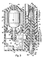
- FIG. 1-3 An antenna assembly 10 embodying the invention is shown in Figures 1-3, comprising a housing 12 for a motor and drive transmission, a supporting tube 14 for supporting the assembly and for housing a collapsible antenna mast 15 comprised of telescoping sections 16, and a flexible storage tube 22 for a flexible cord that extends and retracts the telescoping sections 16a-d.
- the housing 12 is elongated and very little wider than the supporting tube 14. The assembly is very compact and can be mounted within a small space.
- the housing 12 is formed of three injection moulded plastic pieces 26, 28, 30, that interfit to form a strong enclosure. Pieces 26, 28 together form a cavity 31 for a printed circuit board and switch assembly 32 and a drive transmission 34.
- the housing piece 26 has a cylindrical boss 36 projecting perpendicularly from a top wall 38 to connect with the supporting tube 14.
- the housing piece 28 has a cylindrical boss 40 extending perpendicular to a bottom wall 41, aligned with the boss 36, and accommodating connection of the flexible storage tube 22 with the housing.
- a central opening 42 extends through the boss 36 and a central opening 44 extends through the boss 40, each axially aligned with the other, to accomodate passage of a flexible cord 46 through the housing.
- the cord is connected to a centre antenna section 16a by a coupling tube 43 which is crimped about the cord 46 and centre section 16a.
- the cord 46 extends into the storage tube 22.
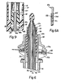
- the cord is of plastic, such as Delrin, and is externally threaded on two diametrically opposite portions.
- the cord has two diametrically opposite flat outer surfaces 46a, 46b along its length, resulting in peripherally broken threads.
- the cord passes through a central opening 48 of a tubular plastic insulator 45 within the boss 36, the. insulator being cylindrical and slidably received within a cylindrical wall 47 within the boss 36.
- the insulator is partially received within the base of the fixed tube 16e and the two are secured together, as by crimping or otherwise, deforming a part of the tube in the insulator.
- Two opposed flat surfaces 48a, 48b of the plastic insulator prevent rotation of the cord 46 relative to the housing, yet provide sufficient clearance to allow free sliding of the cord. Because the inside passage 48 is subject to wear from the movement of the cord 46 it is made long relative to its diameter (several times as long) and is replaceable within the housing.
- two passages 49 ( Figure 9) are provided in the boss 36.
- the passages open at one end 49a in communication with drains 45a, 45b in the tubular insulator 45 and at the other end 49b at the exterior of the housing below the supporting tube 14, and are inclined downwardly and outwardly.
- the drains 45a, 45b are located above an 0-ring seal 53 at the base of the insulator 45, between the insulator and the housing wall 38.
- An upper end of the support tube 14 is securely fastened by brazing or welding to a metal mounting member 54, which extends through an opening in a mounting sheet 55 such as an automobile fender or the like ( Figure 6).
- Top 57a and bottom 57b mounting brackets orient the antenna sections 16a-e at any desired angle with respect to the sheet 55 so that the antenna rises in the desired direction when it is extended.
- a tubular plastic insulator 63 fits closely around the upper end of the outer fixed antenna tube 16d and includes a circular external shoulder 63a, which rests against an upper end of the mounting member 54. With the insulator 63 in place, a retaining nut 65 having an inner threaded portion is tightened down over an outer threaded portion of the mounting member 54 until the brackets 57a, 57b and mounting member 54 are securely mounted to the sheet 55.
- the antenna sections 16a-d are replaceable so that if any are broken or bent an entire unit of those sections 16a-d may be removed and replaced.
- the outer section 16d is retained within the fixed antenna tube 16e by a retaining collar 67 that has a central opening 67a closely surrounding the section 16d which is too small to allow the enlarged base portion 16d ( Figure 3) to pass through.
- the collar 67 has an internal thread 67b that engages a threaded exterior portion 16e-d at the extending end of the fixed antenna tube 16e.
- a reduced diameter portion 67c telescopes into a cylindrical recess 69 formed between the end of the outer tube 16e and the insulator 63.
- a circumferential flange 67d abuts the end of the insulator 63.
- the housing piece 26 ( Figure 3) has an opening 50 in the top wall 38, in which a spherical bearing 51 is located that rotationally supports an armature shaft 52 of a motor 60 along an axis that is parallel to the longitudinal extent of the antenna mast 15.
- the housing piece 30 is a generally cylindrical, cup-like, member that carries a spherical bearing 56 at an upper end, in which the armature shaft 52 is journalled. It also carries permanent motor field magnets 58 which are bounded by an iron shield 58a that protects the magnets 58 from exposure to extremely low temperatures which can reduce the intensity of the magnetic field they create.
- the drive transmission 34 has a drive pulley 61 in the cavity 31, secured to the end of the motor shaft 52, which extends through the top wall 38 into the cavity 31.
- a driven pulley 62 is supported laterally to one side of the drive pulley 61, between two bearings 72, 74.
- the bearing 72 is secured in the housing piece 26 and the bearing 74 in the housing piece 28, each adjacent a respective boss 36, 40, mounting the pulley 62 in axial alignment with the central openings 42, 44 that together form a through passage.
- the driven pulley 62 is of a two piece construction.
- a hub portion 64 ( Figures 3 and 7) has top and bottom flanges 66a, 66b that rotatably support a sleeve 68 having gear teeth about its periphery.
- the hub 64 has a central through passage with internal threads 70 that engage the threads of the cord 46 and acts as a rotary nut to drive the cord.
- a timing belt 78 driven by the pulley 61 engages the teeth on the sleeve 68 which rotates the hub 64 through an overrunning clutch 84.
- the clutch 84 is interposed between the sleeve 68 and hub 64 so that rotation from the sleeve to the hub is transmitted through the clutch 84.
- the threaded relationship of the hub 64 and the cord 46 results in the longitudinal movement of the cord 46 upon rotation of the hub 64, which is restrained from axial movement by the bearings 72, 74.
- rotation of the hub through the transmission 34 drives the cord in a direction to extend the antenna sections or retract them, depending upon the direction of motor rotation.
- the pulley 61 is substantially smaller in diameter than the pulley 62, a speed reduction and power increase result.
- the flange 66b is integral with the hub 64.
- the flange 66a is keyed to the hub and secured to the flange 66b by extensions 66c that extend into holes in the flange 66b and are heat welded in place.
- the clutch 84 automatically decreases the force by which the hub and sleeve are interengaged when the antenna reaches the end of its travel during extension or retraction.
- the clutch overruns smoothly and without generation of excessive heat. This is accomplished by the use of a spring strip wrapped in a ring-like shape within an inside cylindrical surface 86 of the sleeve 68. The resilience of the spring strip causes it to engage the inside cylindrical surface 86 with sufficient force to frictionally rotate with the driven pulley under the loads experienced during extending and retracting the antenna sections when the sections are not obstructed.
- the spring strip encircles the hub 64 and has an inturned flange at 84a, 84b at each opposite end, received in a notch 88 in the hub 64.
- the notch is sufficiently large cicumferentially to allow some peripheral movement of the ends of the spring, which are spaced from each other peripherally a short distance, as best illustrated in Figure 8.
- the spring surrounds the outside diameter of the adjacent nut portion with radial clearance. Rotation of the sleeve, transmitted to the spring through friction, causes rotation of the hub by contact of one of the flanges 84a, 84b of the spring with an end of the receiving notch 88.
- the upper boss 36 receives the supporting tube 14 in closely surrounding relation.
- the mast is secured to and supported by the insulator 45, which compresses the 0-ring seal 53.
- the mast 15 and attached cord 46 is inserted into the tube 14 so the cord 46 can be inserted into the opening in the hub 64.
- the insulator 45 is oriented so its drains 45a, 45b communicate with the passageways 49 ( Figure 9) which, in a preferred embodiment, leads away from the threads on the cord 46 to the exterior of the housing 26.
- the motor 60 is energized in a direction to draw the cord 46 into the hub 64 until the mast approaches the position shown in Figure 3, i.e.
- the mast 15 is inserted a slight distance further until the collar 67 completely seats in the recess 69, with the flange 67d abutting the end of the insulator 63. This additional movement is accomplished by compressing the 0-ring seal between the insulator 45 and a restricted region 71 of the housing member 26 through which the hub portion of the driven pulley 62 fits.
- threaded connectors 73 with pointed ends are screwed through the tube 14 and boss 36, into the insulator 45 securely positioning the mast in place.
- three connectors 73 are used. In the event of damage to the core sections 16a-d those sections may be replaced as outlined above without removing the outermost section 16e which is fastened to the insulator 45.
- the storage tube 22 for housing the cord 46 fits inside the boss 40.
- the tube has a shoulder 82 on the end to retain it within the housing.
- the storage tube 22, being flexible, can be bent to whatever contour desired, depending upon the wheel well shape and construction in which the assembly is mounted, to provide an enclosure for the cord 46 when the antenna mast is collapsed. Alternatively, it can be preformed to a desired contour.
- FIG. 4 A schematic wiring diagram of the switch assembly 32 located within the housing piece 28 is shown in Figure 4. As shown, power from a battery such as an automobile battery is supplied to the DC motor 60 through lines 90, 91. The direction of the motor is controlled by the polarity of the current applied through the leads, which can be changed through a double pole, double throw, centre off toggle switch SW1 mounted to an automobile dashboard.
- a battery such as an automobile battery
- the direction of the motor is controlled by the polarity of the current applied through the leads, which can be changed through a double pole, double throw, centre off toggle switch SW1 mounted to an automobile dashboard.
- a switching circuit 89 is interposed in the lead 91 by two connecting leads 93, 94. Both leads 93, 94 connect to a rectifying bridge type circuit 96 from which two lines 98, 99 of the switching circuit are connected.
- the bridge circuit 96 maintains a first junction 95 negative and a second junction 97 positive regardless of the polarity of the switch SW1 to allow the switching circuit to operate regardless of a change of polarity at the connections 93, 94 when current to the motor 60 is reversed.
- the switch circuit 89 removes the power from the motor when a preset time and current load conditions have been met, such as a short time after the motor reaches the end of its travel and a greatly increased load and hence current demand is placed upon the motor 60.
- the automobile battery now drives the motor 60 through the 1k resistor R5 instead of the 1 ohm resistor R6.
- the current through the motor 60 drops to a point where the motor no longer rotates. This state continues until the user toggles the switch SW-1 back to its centre off position.
- a magnet 98 is located in the flange 66b adjacent a Hall-effect transducer 99 and associated circuitry 100 that replaces the switch circuit 89.
- the Hall-effect switch senses rotation of the magnet 98 which rotates in excess of 20 revolutions per second when the motor is extending or retracting the antenna.
- Two inputs M1, M2 to the circuit 100 are motor inputs which drive the motor in one of two directions depending on the polarity of two inputs IP-1, IP-2 from a switch SW2.
- the switch SW2 is a double throw, double pole switch whose polarity is controlled by a relay (not shown) having a holding coil energized through the radio.
- a relay not shown
- the switch polarity retracts the antenna and when the coil is energized the polarity is switched to extend the antenna.
- the antenna will extend automatically whenever the ignition and radio are both activated and will retract when either the radio or the ignition is switched off.
- the motor 60 is also energized by the car battery (not shown) so the retraction of the antenna is accomplished even though the ignition is switched off.
- the signal applied to IP-1 and IP-2 is a DC signal so that after the initial receipt of that signal the two capacitors C2 and C3 will block the transmission of those signals to the base of the transistor Q2.
- the motor would receive a signal temporarily and once the blocking effect of C2 and C3 take effect, motor rotation would terminate.
- the Hall-effect transducer 99 senses magnet rotation and generates pulses at its terminal labeled #3 in Figure 5. These pulses are coupled through a capacitor C4 and a diode to the base of the transistor Q2. Periodic receipt of this pulse continues to bias transistor Q2 into conduction which in turn keeps one power transistor (Q3 or Q4) turned on maintaining the motor drive signals at M1 and M2. In the event the motor drive action moves the antenna to one of its limits of travel, continued movement is no longer possible and the Hall transducer no longer generates these pulses. Once these pulses stop the transistor Q2 also ceases to conduct since its base emitter junction no longer has the necessary voltage across it and for a similar reason the power transistor (either Q3 or Q4) also stops conducting.
- a transistor Q1 insures that the alternating pulses appearing at the base of the transistor Q2 are generated from movement of the antenna drive and not from spurious vibrations in the car fender.
- IP-1 or IP-2 which initially biases transistor Q2 into conduction appears at the base of transistor Q1 to cause conduction in that transistor.
- This transistor will continue to conduct until transistor Q2 turns off at which time transistor Q1 also turns off disabling the Hall-effect transducer.
- the Hall-effect transducer is only capable of transmitting pulses when transistor Q1 conducts and this transistor in turn can only conduct when an input appears at either IP-1 or IP-2. Once the end of travel has been reached and the transistor Q1 is turned off, spurious vibrations to the Hall-effect transducer will never reinitiate conduction in transistor Q2 without the appearance of the signal at IP-1 or IP-2.
- the circuit 100 ( Figure 5) is preferable to the circuit 89 ( Figure 4) since the user need not deactivate the circuit 100 after the motor 60 has fully extended or retracted the antenna. After the car ignition is turned off, IP-1 and IP-2 are still coupled to the battery by the switch SW2 but when all transistors are turned off the circuit 100 draws only about 3 milliamps, a current the battery can supply for over 3000 hours without any problem.
- the Hall-effect transducer can be replaced with other means for generating a pulse train to maintain the transistor Q2 conductive.
- An optical sensor might be mounted in close proximity to the flange 66b to sense rotation of a mark or irregularity in the flange.
- the irregularity might comprise, for instance, castellations or slots in the flange 66b which would preferably trigger the optical sensor.
- Such an optical sensor would include an infra-red radiation source which would be insensitive to dirt build-up in the vicinity of the flange 66b.
- the length L ( Figure 1) is 2.84 inches and the height H is 3.75 inches.
- the width W ( Figure 2) is 1.20 inches and the diameter D of the supporting tube 14 is 0.8 inches.
- the housing width has been kept to no more than 1.5 times greater than the width of the supporting tube and the length no more than 3.6 times greater.
- the overall height of the housing and antenna, except for the storage tube 22, with the antenna collapsed, is 12.4 inches.
- the weight of the preferred embodiment is 15.9 ounces, which is sufficiently light to permit mounting with top hardware (i.e., a bracket or the like at the top of the supporting tube 14) only.
- the small size of the housing occupies an extremely small volume within a wheel well of the vehicle, which is highly desirable to the automobile manufacturer.
Landscapes
- Details Of Aerials (AREA)
Applications Claiming Priority (2)
| Application Number | Priority Date | Filing Date | Title |
|---|---|---|---|
| US06/496,897 US4542383A (en) | 1983-05-23 | 1983-05-23 | Replaceable motor operated antenna |
| US496897 | 1983-05-23 |
Publications (1)
| Publication Number | Publication Date |
|---|---|
| EP0127352A2 true EP0127352A2 (de) | 1984-12-05 |
Family
ID=23974648
Family Applications (1)
| Application Number | Title | Priority Date | Filing Date |
|---|---|---|---|
| EP84303093A Withdrawn EP0127352A2 (de) | 1983-05-23 | 1984-05-08 | Auswechselbare, motorisch aus- und einfahrbare Antenne |
Country Status (3)
| Country | Link |
|---|---|
| US (1) | US4542383A (de) |
| EP (1) | EP0127352A2 (de) |
| JP (1) | JPS59226504A (de) |
Cited By (2)
| Publication number | Priority date | Publication date | Assignee | Title |
|---|---|---|---|---|
| DE3738885A1 (de) * | 1986-11-17 | 1988-05-26 | Gen Motors Corp | Kraftfahrzeug-automatikantennensteuerung mit sperre waehrend des anlassens |
| DE3738887A1 (de) * | 1986-11-17 | 1988-05-26 | Gen Motors Corp | Automatikantennensteuerung mit begrenzung der mechanischen spannungen im antrieb |
Families Citing this family (11)
| Publication number | Priority date | Publication date | Assignee | Title |
|---|---|---|---|---|
| US4649398A (en) * | 1984-01-25 | 1987-03-10 | Nippondenso Co., Ltd. | Motor driven extensible rod antenna for vehicles with position control circuit |
| JPS60169907U (ja) * | 1984-04-20 | 1985-11-11 | 原田工業株式会社 | 車両用伸縮ロツドアンテナ装置 |
| FR2570226B1 (fr) * | 1984-05-16 | 1987-12-24 | Nippon Antenna Kk | Mecanisme pour deployer et retracter une antenne |
| JPH0438563Y2 (de) * | 1984-10-12 | 1992-09-09 | ||
| US4653565A (en) * | 1985-07-25 | 1987-03-31 | Chamberlain Manufacturing Corporation | Garage door opener |
| US5035094A (en) * | 1990-03-26 | 1991-07-30 | Legare David J | Nested extension/retraction structure and method of fabrication |
| US5510686A (en) * | 1994-01-21 | 1996-04-23 | Courtney E. Collier | Automated garage door closer |
| WO2016069024A1 (en) * | 2014-10-29 | 2016-05-06 | Lapham James Troy | Wireless equipment concealment system utilizing an aerial multimedia platform |
| US12030396B2 (en) * | 2014-10-29 | 2024-07-09 | Project Management Resource Group (Pmrg) Corporation | Wireless equipment concealment system utilizing an aerial multimedia platform |
| DE102015104484B4 (de) * | 2015-03-25 | 2016-12-22 | A. Mannesmann Maschinenfabrik Gmbh | Vierstufiger Teleskopaktor mit Gewindetrieb |
| US11831215B2 (en) * | 2021-05-06 | 2023-11-28 | Aac Microtech (Changzhou) Co., Ltd. | Linear vibration motor |
Family Cites Families (5)
| Publication number | Priority date | Publication date | Assignee | Title |
|---|---|---|---|---|
| US2635186A (en) * | 1948-10-07 | 1953-04-14 | Schmidt Thur | Radio antenna |
| US3380062A (en) * | 1967-04-26 | 1968-04-23 | Michael P. George | Telescopic antenna |
| GB1435493A (en) * | 1972-05-18 | 1976-05-12 | Crater Controls Ltd | Aerials |
| US4209792A (en) * | 1978-11-22 | 1980-06-24 | General Motors Corporation | Antenna cable drive and storage drum with stop mechanism |
| US4325069A (en) * | 1980-02-07 | 1982-04-13 | Jimmy's Radio & Televison Corp. | Convertible telescopic antenna |
-
1983
- 1983-05-23 US US06/496,897 patent/US4542383A/en not_active Expired - Fee Related
-
1984
- 1984-05-08 EP EP84303093A patent/EP0127352A2/de not_active Withdrawn
- 1984-05-23 JP JP59104412A patent/JPS59226504A/ja active Pending
Cited By (2)
| Publication number | Priority date | Publication date | Assignee | Title |
|---|---|---|---|---|
| DE3738885A1 (de) * | 1986-11-17 | 1988-05-26 | Gen Motors Corp | Kraftfahrzeug-automatikantennensteuerung mit sperre waehrend des anlassens |
| DE3738887A1 (de) * | 1986-11-17 | 1988-05-26 | Gen Motors Corp | Automatikantennensteuerung mit begrenzung der mechanischen spannungen im antrieb |
Also Published As
| Publication number | Publication date |
|---|---|
| US4542383A (en) | 1985-09-17 |
| JPS59226504A (ja) | 1984-12-19 |
Similar Documents
| Publication | Publication Date | Title |
|---|---|---|
| US4591868A (en) | Collapsible motor operated antenna | |
| US4542383A (en) | Replaceable motor operated antenna | |
| US5473335A (en) | Base support for movable antenna | |
| US6707188B2 (en) | Motor having rotational sensor | |
| US5684646A (en) | Exterior mirror with single pivot power fold | |
| EP1556630B1 (de) | Stellglied | |
| US4453372A (en) | Grass edger and trimmer attachment | |
| US5065969A (en) | Apparatus for mounting an antenna for rotation on a mast | |
| US3458173A (en) | Trailer jack | |
| US7471020B2 (en) | Linear actuator | |
| US5633647A (en) | Base support for movable antenna | |
| EA000830B1 (ru) | Наружное зеркало с шаговым и контролируемым поворотом | |
| EP0074015A1 (de) | Ferngesteuerter Rückspiegel für Kraftfahrzeuge | |
| US6481550B2 (en) | Motor having clutch provided with stopper | |
| US4649398A (en) | Motor driven extensible rod antenna for vehicles with position control circuit | |
| EP0106882A4 (de) | Versenkbare motorbetriebene antenne. | |
| DE19706871A1 (de) | Elektromotorische Antriebsvorrichtung | |
| JP2005186668A (ja) | モータ駆動装置及び電動格納式ドアミラー | |
| JP2008072776A (ja) | 回転電機 | |
| CA1208353A (en) | Collapsible motor operated antenna | |
| CA1241437A (en) | Extendable directional dipole antenna | |
| US4538155A (en) | Antenna mount with rotary positionable feature | |
| US7270429B2 (en) | Vehicle mirror with powered extension incorporating slip clutch | |
| JPH0753413Y2 (ja) | 2つの部材を同時に駆動するための減速装置 | |
| JPH028501Y2 (de) |
Legal Events
| Date | Code | Title | Description |
|---|---|---|---|
| PUAI | Public reference made under article 153(3) epc to a published international application that has entered the european phase |
Free format text: ORIGINAL CODE: 0009012 |
|
| AK | Designated contracting states |
Designated state(s): AT DE FR GB SE |
|
| STAA | Information on the status of an ep patent application or granted ep patent |
Free format text: STATUS: THE APPLICATION IS DEEMED TO BE WITHDRAWN |
|
| 18D | Application deemed to be withdrawn |
Effective date: 19870310 |
|
| RIN1 | Information on inventor provided before grant (corrected) |
Inventor name: KINARD, JOHN M. Inventor name: CUSEY, DAR L. |