EP0127346B1 - Peristaltic pumps - Google Patents
Peristaltic pumps Download PDFInfo
- Publication number
- EP0127346B1 EP0127346B1 EP84302990A EP84302990A EP0127346B1 EP 0127346 B1 EP0127346 B1 EP 0127346B1 EP 84302990 A EP84302990 A EP 84302990A EP 84302990 A EP84302990 A EP 84302990A EP 0127346 B1 EP0127346 B1 EP 0127346B1
- Authority
- EP
- European Patent Office
- Prior art keywords
- motor
- skip
- drive
- pump
- speed
- Prior art date
- Legal status (The legal status is an assumption and is not a legal conclusion. Google has not performed a legal analysis and makes no representation as to the accuracy of the status listed.)
- Expired
Links
- 230000002572 peristaltic effect Effects 0.000 title claims abstract description 28
- 239000012530 fluid Substances 0.000 claims abstract description 25
- 238000005086 pumping Methods 0.000 claims abstract description 22
- 238000012545 processing Methods 0.000 claims abstract description 14
- 238000001514 detection method Methods 0.000 claims abstract description 9
- 230000001105 regulatory effect Effects 0.000 claims description 13
- 230000001276 controlling effect Effects 0.000 claims description 7
- 238000000034 method Methods 0.000 claims description 6
- 230000004044 response Effects 0.000 claims description 3
- 101100508818 Mus musculus Inpp5k gene Proteins 0.000 description 21
- 101100366438 Rattus norvegicus Sphkap gene Proteins 0.000 description 21
- 238000001802 infusion Methods 0.000 description 4
- 230000009471 action Effects 0.000 description 3
- 238000012544 monitoring process Methods 0.000 description 3
- 238000013459 approach Methods 0.000 description 2
- 238000012937 correction Methods 0.000 description 2
- 230000004580 weight loss Effects 0.000 description 2
- 230000005540 biological transmission Effects 0.000 description 1
- 230000008859 change Effects 0.000 description 1
- 238000010276 construction Methods 0.000 description 1
- 239000013078 crystal Substances 0.000 description 1
- 238000010586 diagram Methods 0.000 description 1
- 230000009977 dual effect Effects 0.000 description 1
- 230000000694 effects Effects 0.000 description 1
- 230000006870 function Effects 0.000 description 1
- 239000003978 infusion fluid Substances 0.000 description 1
- 230000007246 mechanism Effects 0.000 description 1
- 230000008569 process Effects 0.000 description 1
- 239000010453 quartz Substances 0.000 description 1
- VYPSYNLAJGMNEJ-UHFFFAOYSA-N silicon dioxide Inorganic materials O=[Si]=O VYPSYNLAJGMNEJ-UHFFFAOYSA-N 0.000 description 1
- 230000001360 synchronised effect Effects 0.000 description 1
- 238000012360 testing method Methods 0.000 description 1
Images

Classifications
-
- G—PHYSICS
- G05—CONTROLLING; REGULATING
- G05D—SYSTEMS FOR CONTROLLING OR REGULATING NON-ELECTRIC VARIABLES
- G05D7/00—Control of flow
- G05D7/06—Control of flow characterised by the use of electric means
- G05D7/0617—Control of flow characterised by the use of electric means specially adapted for fluid materials
- G05D7/0629—Control of flow characterised by the use of electric means specially adapted for fluid materials characterised by the type of regulator means
- G05D7/0676—Control of flow characterised by the use of electric means specially adapted for fluid materials characterised by the type of regulator means by action on flow sources
-
- A—HUMAN NECESSITIES
- A61—MEDICAL OR VETERINARY SCIENCE; HYGIENE
- A61M—DEVICES FOR INTRODUCING MEDIA INTO, OR ONTO, THE BODY; DEVICES FOR TRANSDUCING BODY MEDIA OR FOR TAKING MEDIA FROM THE BODY; DEVICES FOR PRODUCING OR ENDING SLEEP OR STUPOR
- A61M5/00—Devices for bringing media into the body in a subcutaneous, intra-vascular or intramuscular way; Accessories therefor, e.g. filling or cleaning devices, arm-rests
- A61M5/14—Infusion devices, e.g. infusing by gravity; Blood infusion; Accessories therefor
- A61M5/168—Means for controlling media flow to the body or for metering media to the body, e.g. drip meters, counters ; Monitoring media flow to the body
- A61M5/172—Means for controlling media flow to the body or for metering media to the body, e.g. drip meters, counters ; Monitoring media flow to the body electrical or electronic
-
- H—ELECTRICITY
- H02—GENERATION; CONVERSION OR DISTRIBUTION OF ELECTRIC POWER
- H02P—CONTROL OR REGULATION OF ELECTRIC MOTORS, ELECTRIC GENERATORS OR DYNAMO-ELECTRIC CONVERTERS; CONTROLLING TRANSFORMERS, REACTORS OR CHOKE COILS
- H02P8/00—Arrangements for controlling dynamo-electric motors rotating step by step
- H02P8/14—Arrangements for controlling speed or speed and torque
Definitions
- the present invention is concerned with improving the operating characteristics of peristaltic pumps, more particularly, by regulating the operation of the pump drive motor. Whilst it is specifically directed to improving the operation of peristaltic medical infusion pumps, it is equally applicable to other peristaltic pumps where volumetric accuracy and constancy or uniformity of flow are important requirements.
- the peristaltic pumping action is well suited for use in a medical infusion pump because it is applied externally to the fluid delivery tube and, consequently, does not interfere with the sterile state which must be maintained for the infusion fluid within the tube. Furthermore, the pumping action can be applied at any point on the delivery tube of a simple I.V. set, thus avoiding the need for special and expensive I.V. sets of the cassette type, as used on many volumetric infusion pumps.
- peristaltic pump There are various types of peristaltic pump, but the simplest, most reliable and least expensive is that based on a rotary action in which a rotary pump head, including a plurality of rollers, is rotated to engage the rollers successively with a delivery tube to pump fluid along the tube. This type of rotary pump mechanism is well known.
- a major problem which exists in peristaltic pumps is that the resulting delivery of fluid occurs in a series of pulses or surges, the frequency of which is equal for example, to the frequency of the passage of successive rollers of a rotary peristaltic pump in contact with the delivery tube.
- This flow pattern is inherent in conventional peristaltic pumps. The effect is that fluid is delivered at a widely varying rate during a pump cycle and this can be unacceptable in infusion procedures in which uniformity of delivery rate is a requirement.
- the continuous change in flow rate can cause instability in sensitive feedback control systems which are designed to ensure that fluid is delivered at a constant rate.
- One convenient device for driving a perstaltic pump is a stepping motor, since such a motor is capable of offering a wide range of rotational speeds using a simple, gearless direct drive transmission. Also, the digital system used to rotate the motor is well suited to the type of electronic motor speed control circuitry used with a feedback loop system for maintaining accuracy of pumping performance.
- control apparatus for the drive motor of a peristaltic pump having rotary means driven by the drive motor comprising motor speed regulating means for supplying an adjustable drive signal to the motor, processing means responsive to control means for adjusting the regulating means so as alternately to operate the motor at a normal speed, which drives the pump at a predetermined.
- the drive motor is arranged to rotate more rapidly during periods corresponding to the dwell periods, when no or reduced fluid flow would normally occur, and consequently the pump functions to deliver fluid at a more constant or uniform flow rate than hitherto.
- the invention also consists in a method of controlling the drive motor of a peristaltic pump having rotary means driven by the drive motor, comprising the steps of supplying an adjustable drive signal for the motor, regulating the drive signal so as alternately to operate the motor at a normal speed, which drives the pump at a predetermined pumping rate, and at an increased speed for a predetermined skip period which corresponds to the dwell period of each peristaltic cycle of the pump, thereby to achieve more uniform flow of fluid being pumped, detecting indexing means associated with the rotary means and defining a predetermined position of the rotary means relatively to each skip period, and synchronising the normal speed and skip periods with the detection of the indexing means.
- the invention is particularly suitable for controlling the operation of a stepping motor drive of a peristaltic pump.
- the regulating means comprises a speed pulse counter for supplying drive pulses for the stepping motor at an adjustable pulse rate.
- the processing means controls the setting of the counter so that the speed of the motor normally corresponds to the predetermined pumping rate. It is arranged to be responsive to the control means so as to adjust the counter to increase the drive pulse rate and, thus, the motor speed, for a predetermined number of steps of the motor corresponding to a flow dwell period, whereafter the control means signals the processing means to reset the counter so as to rotate the motor at the predetermined pumping rate until the next dwell period.
- the stepping motor By arranging the stepping motor to index rapidly through a number of steps, which is equivalent to the dwell period, so that these steps are covered, for example, in a time approximately equivalent to one step during the period in which flow is normally maintained by the pump, the latter can be operated to deliver at a constant rate throughout its entire running cycle.
- This rapid indexing of "skipping" of the motor must start at the beginning-ôf a dwell period.
- the invention enables monitoring of the operation of the stepping motor and detection of when it is overloaded or stalled.
- the stepping motor is arranged to operate in a succession of alternate run and skip sequences, each of which occurs over a predetermined number of steps of the motor.
- the invention may be incorporated in flow control apparatus, as described in our prior patent application EP-A-0100682, for a fluid dispensing system in which fluid is dispensed from a fluid container under the control of a rotary peristaltic pump.
- the processing means is also arranged to be responsive to selection means for selecting a required flow rate and a weight sensing device for monitoring the weight loss of the fluid container as fluid is dispensed therefrom. It compares the selected flow rate with actual flow rate data derived from weight loss signals supplied by the weight sensing device and controls the regulating means so as also to adjust the speed of the pump motor in such a manner that the actual flow rate approaches or corresponds to the selected rate.
- FIG. 1 schematically illustrates a stepping motor connected to drive the pump head 2 of a rotary peristaltic pump.
- This pump head includes several rollers 3, arranged to be rotated successively into engagement with a delivery tube which is urged into engagement with the pump head by a tube holder (not shown) so that fluid is pumped along the delivery tube by a peristaltic action upon rotation of the head.
- the construction of such a peristaltic pump is well known and will not be described in more detail as it does not, itself, form part of the present invention.
- the stepping motor may, for example, be a four- phase motor having a 1.8° step that is, 200 steps per revolution. Trains of drive pulses are supplied to the motor via a conventional phase sequencer and drive logic circuit 4 and drive amplifiers 5.
- the control circuitry for the stepping motor comprises a central processing unit 6, conveniently, a microprocessor, such as, the 8-bit microprocessor marketed by RCA Inc. under the Model No. CDP 1806 Ace, having a program memory 7 (Read Only Memory or ROM) accessed via an address bus 8.
- a weight sensor 9 monitors the weight of a fluid container (not shown) from which fluid is dispensed under the control of the pump and produces weight signals corresponding to the loss in weight of the container as fluid is dispensed. These weight signals are processed by the microprocessor 6 which produces therefrom data identifying the actual flow rate.
- the microprocessor 6, program memory 7 and the weight sensor 9 are interconnected by control and data buses 10, 11 and the arrangement of these components may be similar to the electronic flow control circuitry of the system described in our aforementioned EP-A-0100682.
- a train of timing pulses is supplied by a quartz crystal oscillator 12 which is connected to the microprocessor 6 and, via a clock divider 13 feeding pulses at a constant rate, to a dual 16-bit binary presettable downcounter 14.
- One 16-bit counter 15 of this downcounter is connected to supply drive pulses to the phase sequencer and drive logic 4 of the stepping motor, whilst the other is separated into two 8-bit downcounters 16, 17 respectively controlling the numbers of steps of the stepping motor to be operated at skip and normal running speeds.
- the counter 15 serves as a variable pulse divider for producing motor drive pulse trains at different repetition rates for regulating the speed of rotation of the stepping motor.
- the counters 15, 16, 17 are controlled by the microprocessor to which they are connected by the control and data buses 10, 11.
- a photo sensor 18 for detecting the rotational position of the head. It senses several indexing marks 19 which are equally spaced about the pump head in predetermined positions with respect to the rollers 3 and corresponding to the start of skip period for each roller. In response to sensing a mark 19, the sensor 18 supplies an interrupt signal to the microprocessor via the line 20 and the control bus 10.
- a desired pumping rate is first selected and data identifying the selected rate is loaded into the microprocessor 6.
- the latter stores this data and determines the initial speed at which the stepping motor 1 should rotate, in order nominally to deliver the selected flow rate by reference to the program memory 7.
- an initial motor speed latch (IMS latch) is set and the microprocessor loads this motor speed information onto the data bus 11 for presetting the buffer register of the motor speed counter 15 preparatory to loading the speed counter control register at the next step to implement the required speed and enable the counter.
- IMS latch initial motor speed latch
- the counter 15 supplies a train of pulses to the phase sequencer and drive logic 4 at the required pulse rate to drive the motor 1 at a speed nominally corresponding to the selected pumping rate.
- the microprocessor 6 Whilst pumping proceeds, the microprocessor 6 also receives data from the weight sensor 9 and processes this to produce data identifying the actual flow rate. It sequentially compares this data with the selected rate data and accesses the program memory 7 so that data is supplied to the counter 15 to adjust the motor speed in such a manner that the actual pumping rate approaches the selected pumping rate.
- the IMS latch is reset and the new motor speed data is preset into the buffer register of the counter 15 preparatory to loading into the control register of this counter at the next increment similarly to the initial motor speed setting.
- the microprocessor 6 Upon starting of the motor 1, the microprocessor 6 interrogates the IMS latch and, detecting this to be set, loads solely into the buffer register of the run counter 17 a count corresponding to the number of steps at which the motor is to be operated at normal running speed. This count is then loaded into the control register of the run counter and enables the latter.
- the run counter As the motor rotates, the run counter is downcounted by motor drive pulses from the counter 15 and, since the number of run steps of the motor exceeds the skip steps, assuming normal operation, the sensor 18 will detect a mark 19 on the head during this downcount, and an interrupt signal will be produced on the line 20 to set a sensor 18 latch. Each time the sensor detects a mark 19 the interrupt signal also sets a sensor 18 flag.
- the microprocessor Upon starting of the motor, the microprocessor repeatedly interrogates the sensor flag until it detects that this is set, whereupon the sensor latch is set and control returns to the main program.
- a run counter zero interrupt signal is supplied by the main program of the microprocessor which signals the microprocessor to load the buffer registers of both the skip and run counters 16, 17 with the predetermined skip and run counts preparatory to loading into the control registers of those counters. If the sensor latch or flag has not been set, upon the occurrence of the zero interrupt signal from the main program, or the zero interrupt signal produced by the run counter 17, itself, upon being downcounted to zero, this indicates that the pump is overloaded or stalled and the program calls a pump stall alarm.
- the skip and run counters 16, 17 control the operation of the motor speed counter 15 so that the motor is alternately driven at the different speed normal run and skip rates.
- the run counter 17 produces the abovementioned zero interrupt signal and providing this is in synchronism with the interrupt signal produced by the sensor 18 upon sensing a mark 19 on the head, the motor is operating properly. If it does not, then the program calls into operation the head stall alarm and stops the motor. If the microprocessor 6 makes a motor speed correction during operation of the pump, upon detecting the IMS latch to be reset, it merely maintains the buffer registers of the skip and run counters 16,17 loaded with the predetermined skip and run counts.
- the interrupt signal produced by the sensor 18 signals the microprocessor to reset the count in the motor speed counter 15 to the required value for the higher skip rate and motor drive pulses are supplied at this rate for the numebr of motor steps determined by the skip counter 16. Since it is desirable to complete the skip sequence in the minimum possible time the step rate during this sequence is fixed at the fastest rate at which the motor operates, that is, of the order of 500 steps per second.
- the microprocessor After the predetermined number of motor steps controlled by the skip counter 16, the microprocessor resets the register of the motor speed counter 15 to the normal running value determined to be required to achieve the selected flow rate, and the motor 1 is then driven at this slower running rate for the number of steps determined by the run counter 17 and until the next interrupt signal is produced by the sensor 18 and the microprocessor checks that this is synchronized with the zero interrupt signal produced on zeroising of the run counter 17, whereupon the sequences of operations is repeated.
Landscapes
- Health & Medical Sciences (AREA)
- Engineering & Computer Science (AREA)
- Biomedical Technology (AREA)
- Life Sciences & Earth Sciences (AREA)
- Automation & Control Theory (AREA)
- Physics & Mathematics (AREA)
- Vascular Medicine (AREA)
- Anesthesiology (AREA)
- Power Engineering (AREA)
- Heart & Thoracic Surgery (AREA)
- Hematology (AREA)
- General Physics & Mathematics (AREA)
- Animal Behavior & Ethology (AREA)
- General Health & Medical Sciences (AREA)
- Public Health (AREA)
- Veterinary Medicine (AREA)
- Reciprocating Pumps (AREA)
- Saccharide Compounds (AREA)
- Control Of Stepping Motors (AREA)
Abstract
Description
- The present invention is concerned with improving the operating characteristics of peristaltic pumps, more particularly, by regulating the operation of the pump drive motor. Whilst it is specifically directed to improving the operation of peristaltic medical infusion pumps, it is equally applicable to other peristaltic pumps where volumetric accuracy and constancy or uniformity of flow are important requirements.
- The peristaltic pumping action is well suited for use in a medical infusion pump because it is applied externally to the fluid delivery tube and, consequently, does not interfere with the sterile state which must be maintained for the infusion fluid within the tube. Furthermore, the pumping action can be applied at any point on the delivery tube of a simple I.V. set, thus avoiding the need for special and expensive I.V. sets of the cassette type, as used on many volumetric infusion pumps.
- There are various types of peristaltic pump, but the simplest, most reliable and least expensive is that based on a rotary action in which a rotary pump head, including a plurality of rollers, is rotated to engage the rollers successively with a delivery tube to pump fluid along the tube. This type of rotary pump mechanism is well known.
- A major problem which exists in peristaltic pumps is that the resulting delivery of fluid occurs in a series of pulses or surges, the frequency of which is equal for example, to the frequency of the passage of successive rollers of a rotary peristaltic pump in contact with the delivery tube. This flow pattern is inherent in conventional peristaltic pumps. The effect is that fluid is delivered at a widely varying rate during a pump cycle and this can be unacceptable in infusion procedures in which uniformity of delivery rate is a requirement. Moreover, the continuous change in flow rate can cause instability in sensitive feedback control systems which are designed to ensure that fluid is delivered at a constant rate.
- One convenient device for driving a perstaltic pump is a stepping motor, since such a motor is capable of offering a wide range of rotational speeds using a simple, gearless direct drive transmission. Also, the digital system used to rotate the motor is well suited to the type of electronic motor speed control circuitry used with a feedback loop system for maintaining accuracy of pumping performance.
- In tests carried out on a typical rotary peristaltic pump arrangement, driven by a stepping motor for the purposes of monitoring the flow pattern of fluid delivered by the pump, it was found that during the passage of each roller in contact with the delivery tube, constant flow was maintained through the tube for 26 steps of the motor, immediately followed by a sequence of 14 motor steps during which there was no flow at all in the down-stream or positive direction. During this dwell period, there was often some evidence of negative flow. This means that, in normal operation, the pump is delivering no fluid for over one- third of its operating time and is delivering fluid at a rate 50% higher than the average rate for nearly two-thirds of the time.
- It is an object of the present invention to alleviate the aforementioned problem experienced with existing perstaltic pumps and to provide for control of the pump drive motor so as to achieve a more constant flow rate throughout the cycle of operations of such a pump.
- To this end, the invention consists in control apparatus for the drive motor of a peristaltic pump having rotary means driven by the drive motor, comprising motor speed regulating means for supplying an adjustable drive signal to the motor, processing means responsive to control means for adjusting the regulating means so as alternately to operate the motor at a normal speed, which drives the pump at a predetermined. pumping rate, and at an increased speed for a predetermined skip period which corresponds to the dwell period of each peristaltic cycle of the pump, whereby to achieve more uniform flow of fluid being pumped, indexing means associated with the rotary means and defining a predetermined position of the rotary means relatively to each skip period, and sensing means for detecting the indexing means, said processing means being responsive to said sensing means detecting said indexing means to synchronise the operation of said control means with the detection of said indexing means. Hence, with the invention, the drive motor is arranged to rotate more rapidly during periods corresponding to the dwell periods, when no or reduced fluid flow would normally occur, and consequently the pump functions to deliver fluid at a more constant or uniform flow rate than hitherto.
- The invention also consists in a method of controlling the drive motor of a peristaltic pump having rotary means driven by the drive motor, comprising the steps of supplying an adjustable drive signal for the motor, regulating the drive signal so as alternately to operate the motor at a normal speed, which drives the pump at a predetermined pumping rate, and at an increased speed for a predetermined skip period which corresponds to the dwell period of each peristaltic cycle of the pump, thereby to achieve more uniform flow of fluid being pumped, detecting indexing means associated with the rotary means and defining a predetermined position of the rotary means relatively to each skip period, and synchronising the normal speed and skip periods with the detection of the indexing means.
- The invention is particularly suitable for controlling the operation of a stepping motor drive of a peristaltic pump. In this application, the regulating means comprises a speed pulse counter for supplying drive pulses for the stepping motor at an adjustable pulse rate. The processing means controls the setting of the counter so that the speed of the motor normally corresponds to the predetermined pumping rate. It is arranged to be responsive to the control means so as to adjust the counter to increase the drive pulse rate and, thus, the motor speed, for a predetermined number of steps of the motor corresponding to a flow dwell period, whereafter the control means signals the processing means to reset the counter so as to rotate the motor at the predetermined pumping rate until the next dwell period. By arranging the stepping motor to index rapidly through a number of steps, which is equivalent to the dwell period, so that these steps are covered, for example, in a time approximately equivalent to one step during the period in which flow is normally maintained by the pump, the latter can be operated to deliver at a constant rate throughout its entire running cycle. This rapid indexing of "skipping" of the motor must start at the beginning-ôf a dwell period.
- The invention enables monitoring of the operation of the stepping motor and detection of when it is overloaded or stalled. The stepping motor is arranged to operate in a succession of alternate run and skip sequences, each of which occurs over a predetermined number of steps of the motor. Hence, there are a discrete number of motor steps between each detection of the indexing means by the sensing means and, if the motor is operating in synchronism with its drive pulses, this can be detected by sensing coincidence between signals produced by the sensing means and upon delivery of a number of drive pulses corresponding to the discrete number of motor steps between successive detections of the indexing means. If such coincidence does not occur, then the pump is overloaded or stalled and an alarm condition can be called.
- The invention may be incorporated in flow control apparatus, as described in our prior patent application EP-A-0100682, for a fluid dispensing system in which fluid is dispensed from a fluid container under the control of a rotary peristaltic pump. In such apparatus, the processing means is also arranged to be responsive to selection means for selecting a required flow rate and a weight sensing device for monitoring the weight loss of the fluid container as fluid is dispensed therefrom. It compares the selected flow rate with actual flow rate data derived from weight loss signals supplied by the weight sensing device and controls the regulating means so as also to adjust the speed of the pump motor in such a manner that the actual flow rate approaches or corresponds to the selected rate.
- In order that the present invention may be more readily understood, reference will now be made to the accompanying drawings, in which:-
- Figure 1 is a schematic diagram illustrating the drive logic and control circuitry of a rotary peristaltic pump embodying the invention, and
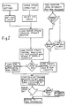
- Figure 2 is a flowchart illustrating the logical steps and operations executed by the CPU in producing skip operation of the stepping motor.
- Referring to Figure 1 of the drawings, 1 schematically illustrates a stepping motor connected to drive the pump head 2 of a rotary peristaltic pump. This pump head includes several rollers 3, arranged to be rotated successively into engagement with a delivery tube which is urged into engagement with the pump head by a tube holder (not shown) so that fluid is pumped along the delivery tube by a peristaltic action upon rotation of the head. The construction of such a peristaltic pump is well known and will not be described in more detail as it does not, itself, form part of the present invention. The stepping motor may, for example, be a four- phase motor having a 1.8° step that is, 200 steps per revolution. Trains of drive pulses are supplied to the motor via a conventional phase sequencer and
drive logic circuit 4 and driveamplifiers 5. - The control circuitry for the stepping motor comprises a
central processing unit 6, conveniently, a microprocessor, such as, the 8-bit microprocessor marketed by RCA Inc. under the Model No. CDP 1806 Ace, having a program memory 7 (Read Only Memory or ROM) accessed via an address bus 8. Aweight sensor 9 monitors the weight of a fluid container (not shown) from which fluid is dispensed under the control of the pump and produces weight signals corresponding to the loss in weight of the container as fluid is dispensed. These weight signals are processed by themicroprocessor 6 which produces therefrom data identifying the actual flow rate. Themicroprocessor 6, program memory 7 and theweight sensor 9 are interconnected by control anddata buses - A train of timing pulses is supplied by a
quartz crystal oscillator 12 which is connected to themicroprocessor 6 and, via aclock divider 13 feeding pulses at a constant rate, to a dual 16-bit binarypresettable downcounter 14. One 16-bit counter 15 of this downcounter is connected to supply drive pulses to the phase sequencer and drivelogic 4 of the stepping motor, whilst the other is separated into two 8-bit downcounters counter 15 serves as a variable pulse divider for producing motor drive pulse trains at different repetition rates for regulating the speed of rotation of the stepping motor. Thecounters data buses - Associated with the rotary pump head 2 is a
photo sensor 18 for detecting the rotational position of the head. It sensesseveral indexing marks 19 which are equally spaced about the pump head in predetermined positions with respect to the rollers 3 and corresponding to the start of skip period for each roller. In response to sensing amark 19, thesensor 18 supplies an interrupt signal to the microprocessor via theline 20 and thecontrol bus 10. - The operation of the pump will now be described and in this connection reference should also be made to the flowchart illustrated in Figure 2. A desired pumping rate is first selected and data identifying the selected rate is loaded into the
microprocessor 6. The latter stores this data and determines the initial speed at which the stepping motor 1 should rotate, in order nominally to deliver the selected flow rate by reference to the program memory 7. Upon fetching of the initial motor setting or speed from the program memory an initial motor speed latch (IMS latch) is set and the microprocessor loads this motor speed information onto thedata bus 11 for presetting the buffer register of themotor speed counter 15 preparatory to loading the speed counter control register at the next step to implement the required speed and enable the counter. Hence, upon commencement of pumping, thecounter 15 supplies a train of pulses to the phase sequencer and drivelogic 4 at the required pulse rate to drive the motor 1 at a speed nominally corresponding to the selected pumping rate. - Whilst pumping proceeds, the
microprocessor 6 also receives data from theweight sensor 9 and processes this to produce data identifying the actual flow rate. It sequentially compares this data with the selected rate data and accesses the program memory 7 so that data is supplied to thecounter 15 to adjust the motor speed in such a manner that the actual pumping rate approaches the selected pumping rate. When a motor speed correction is required, the IMS latch is reset and the new motor speed data is preset into the buffer register of thecounter 15 preparatory to loading into the control register of this counter at the next increment similarly to the initial motor speed setting. - Upon starting of the motor 1, the
microprocessor 6 interrogates the IMS latch and, detecting this to be set, loads solely into the buffer register of the run counter 17 a count corresponding to the number of steps at which the motor is to be operated at normal running speed. This count is then loaded into the control register of the run counter and enables the latter. As the motor rotates, the run counter is downcounted by motor drive pulses from thecounter 15 and, since the number of run steps of the motor exceeds the skip steps, assuming normal operation, thesensor 18 will detect amark 19 on the head during this downcount, and an interrupt signal will be produced on theline 20 to set asensor 18 latch. Each time the sensor detects amark 19 the interrupt signal also sets asensor 18 flag. Upon starting of the motor, the microprocessor repeatedly interrogates the sensor flag until it detects that this is set, whereupon the sensor latch is set and control returns to the main program. When the sensor latch is set, a run counter zero interrupt signal is supplied by the main program of the microprocessor which signals the microprocessor to load the buffer registers of both the skip and runcounters run counter 17, itself, upon being downcounted to zero, this indicates that the pump is overloaded or stalled and the program calls a pump stall alarm. Assuming there is no such fault, the skip and runcounters motor speed counter 15 so that the motor is alternately driven at the different speed normal run and skip rates. At the end of each normal run count, therun counter 17 produces the abovementioned zero interrupt signal and providing this is in synchronism with the interrupt signal produced by thesensor 18 upon sensing amark 19 on the head, the motor is operating properly. If it does not, then the program calls into operation the head stall alarm and stops the motor. If themicroprocessor 6 makes a motor speed correction during operation of the pump, upon detecting the IMS latch to be reset, it merely maintains the buffer registers of the skip and runcounters - When the
sensor 18 detects amark 19 on the pump head and, by this means detects the position at which a skip sequence should commence, the interrupt signal produced by thesensor 18 signals the microprocessor to reset the count in themotor speed counter 15 to the required value for the higher skip rate and motor drive pulses are supplied at this rate for the numebr of motor steps determined by theskip counter 16. Since it is desirable to complete the skip sequence in the minimum possible time the step rate during this sequence is fixed at the fastest rate at which the motor operates, that is, of the order of 500 steps per second. After the predetermined number of motor steps controlled by theskip counter 16, the microprocessor resets the register of themotor speed counter 15 to the normal running value determined to be required to achieve the selected flow rate, and the motor 1 is then driven at this slower running rate for the number of steps determined by therun counter 17 and until the next interrupt signal is produced by thesensor 18 and the microprocessor checks that this is synchronized with the zero interrupt signal produced on zeroising of therun counter 17, whereupon the sequences of operations is repeated.
Claims (7)
Priority Applications (1)
| Application Number | Priority Date | Filing Date | Title |
|---|---|---|---|
| AT84302990T ATE39799T1 (en) | 1983-05-03 | 1984-05-03 | PERISTALTIC PUMP. |
Applications Claiming Priority (2)
| Application Number | Priority Date | Filing Date | Title |
|---|---|---|---|
| GB8312069 | 1983-05-03 | ||
| GB838312069A GB8312069D0 (en) | 1983-05-03 | 1983-05-03 | Peristaltic pumps |
Publications (2)
| Publication Number | Publication Date |
|---|---|
| EP0127346A1 EP0127346A1 (en) | 1984-12-05 |
| EP0127346B1 true EP0127346B1 (en) | 1989-01-04 |
Family
ID=10542069
Family Applications (1)
| Application Number | Title | Priority Date | Filing Date |
|---|---|---|---|
| EP84302990A Expired EP0127346B1 (en) | 1983-05-03 | 1984-05-03 | Peristaltic pumps |
Country Status (7)
| Country | Link |
|---|---|
| US (1) | US4604034A (en) |
| EP (1) | EP0127346B1 (en) |
| JP (1) | JPS6013498A (en) |
| AT (1) | ATE39799T1 (en) |
| CA (1) | CA1238964A (en) |
| DE (1) | DE3476003D1 (en) |
| GB (1) | GB8312069D0 (en) |
Families Citing this family (34)
| Publication number | Priority date | Publication date | Assignee | Title |
|---|---|---|---|---|
| US4778450A (en) * | 1979-07-12 | 1988-10-18 | Baxter Travenol Laboratories, Inc. | Fluid flow control system |
| US4869646A (en) * | 1984-10-15 | 1989-09-26 | American Hospital Supply Corp. | Continuous peristaltic pump |
| EP0181511B1 (en) * | 1984-10-19 | 1990-08-22 | Kollmorgen Corporation | Servomotor control systems |
| US4715786A (en) * | 1984-12-14 | 1987-12-29 | Cole-Parmer Instrument Company | Control method and apparatus for peristaltic fluid pump |
| US4865581A (en) * | 1987-05-29 | 1989-09-12 | Retroperfusion Systems, Inc. | Retroperfusion control apparatus, system and method |
| US4898579A (en) * | 1987-06-26 | 1990-02-06 | Pump Controller Corporation | Infusion pump |
| DE3850492T2 (en) * | 1987-10-14 | 1995-02-16 | Nestle Sa | SURGICAL IRRIGATION AND SUCTION SYSTEM. |
| US4884013A (en) * | 1988-01-15 | 1989-11-28 | Sherwood Medical Company | Motor unit for a fluid pump and method of operation |
| JPH0332396A (en) * | 1989-06-28 | 1991-02-12 | Sharp Corp | Stepping motor driver |
| US5018945A (en) * | 1989-12-14 | 1991-05-28 | Baxter International Inc. | Accurate peristaltic pump |
| US5105140A (en) * | 1990-01-11 | 1992-04-14 | Baxer International Inc. | Peristaltic pump motor drive |
| GB9004005D0 (en) * | 1990-02-22 | 1990-04-18 | Danbury Richard N | Improvements in or relating to the control of stepping motors |
| US5278481A (en) * | 1990-02-22 | 1994-01-11 | British Technological Group Ltd. | Control of stepping motors |
| JPH04156857A (en) * | 1990-10-19 | 1992-05-29 | Sharp Corp | Stepping motor control device for infusion pump |
| US5336167A (en) * | 1991-07-22 | 1994-08-09 | Theratek International, Inc. | Controller for intravascular catheter system |
| US5342180A (en) * | 1992-11-17 | 1994-08-30 | Ivac Corporation | Pump mechanism having a drive motor with an external rotor |
| NL9301729A (en) * | 1993-10-07 | 1995-05-01 | Zeevenhooven Acat Bv | Method and device for supplying a pressurized medium to a pipe network. |
| WO1995023959A1 (en) * | 1994-03-01 | 1995-09-08 | Tru-Test Limited | Proportional fluid sampler |
| US6234773B1 (en) | 1994-12-06 | 2001-05-22 | B-Braun Medical, Inc. | Linear peristaltic pump with reshaping fingers interdigitated with pumping elements |
| GB9526717D0 (en) * | 1995-12-29 | 1996-02-28 | Shine Thomas A | Digital frequency generator |
| DE19606747A1 (en) * | 1996-02-23 | 1997-08-28 | Scharco Elektronik Gmbh & Co K | Display and position equipment industrial controller e.g. for compressor |
| DE19611637B4 (en) * | 1996-03-25 | 2005-08-11 | Möller Feinmechanik GmbH & Co. KG | Method for operating a peristaltic pump and peristaltic pump for carrying out the method |
| US20040191112A1 (en) * | 2003-03-31 | 2004-09-30 | Steris Inc. | Hydrogen peroxide injection system having closed-loop flow control |
| US20040213684A1 (en) * | 2003-04-24 | 2004-10-28 | Klein Jeffrey A. | Infiltration pump having insulated rollers and programmable foot pedal |
| US20060051217A1 (en) * | 2004-09-08 | 2006-03-09 | Felton Bret S | Sterilizable pump and systems for use with sterile fluids |
| ES3038412T3 (en) * | 2007-05-11 | 2025-10-13 | Hoffmann La Roche | A positive displacement pump |
| US8604709B2 (en) | 2007-07-31 | 2013-12-10 | Lsi Industries, Inc. | Methods and systems for controlling electrical power to DC loads |
| US7598683B1 (en) | 2007-07-31 | 2009-10-06 | Lsi Industries, Inc. | Control of light intensity using pulses of a fixed duration and frequency |
| US8903577B2 (en) | 2009-10-30 | 2014-12-02 | Lsi Industries, Inc. | Traction system for electrically powered vehicles |
| EP2362100B2 (en) * | 2010-02-18 | 2020-07-08 | Grundfos Management A/S | Metering pump aggregate and method for controlling same |
| EP2434635A1 (en) * | 2010-09-28 | 2012-03-28 | Fresenius Kabi Deutschland GmbH | Drive device for a medical pump with a step motor |
| SG10201800584SA (en) * | 2012-12-21 | 2018-03-28 | Deka Products Lp | Syringe pump system |
| US10232111B2 (en) | 2013-12-31 | 2019-03-19 | Abbvie Inc. | Pump, motor and assembly for beneficial agent delivery |
| CN121162499B (en) * | 2025-11-21 | 2026-02-27 | 迈安纳(上海)仪器科技有限公司 | Continuous flow preparation system, process and related equipment for lipid nanoparticles |
Family Cites Families (11)
| Publication number | Priority date | Publication date | Assignee | Title |
|---|---|---|---|---|
| US3249059A (en) * | 1964-03-31 | 1966-05-03 | Everpure | Peristaltic-type pump |
| US3335670A (en) * | 1965-01-25 | 1967-08-15 | Milton Roy Co | Steady flow metering pump |
| US4111336A (en) * | 1977-04-14 | 1978-09-05 | H. F. Henderson Industries | Weight loss control system |
| US4299541A (en) * | 1977-11-29 | 1981-11-10 | Nikkiso Co., Ltd. | Infusion solution injecting pump |
| FR2461126A1 (en) * | 1978-12-15 | 1981-01-30 | Gilson Medical Electronic Fran | PISTON PUMP WITH PRECISELY ADJUSTABLE FLOW |
| JPS56113083A (en) * | 1980-02-12 | 1981-09-05 | Terumo Corp | Choke detection method and device for peristaltic liquid pump |
| US4444546A (en) * | 1980-09-19 | 1984-04-24 | Oximetrix, Inc. | Occlusion detection apparatus and method |
| US4474309A (en) * | 1981-10-22 | 1984-10-02 | Oximetrix, Inc. | Stepping motor control procedure for achieving variable rate, quasi-continuous fluid infusion |
| US4467844A (en) * | 1982-06-24 | 1984-08-28 | Baxter Travenol Laboratories, Inc. | Flow monitoring method and apparatus |
| CA1201999A (en) * | 1982-08-03 | 1986-03-18 | Peter G. Wheeldon | Fluid flow control process and apparatus |
| US4468219A (en) * | 1983-12-20 | 1984-08-28 | International Business Machines Corporation | Pump flow rate compensation system |
-
1983
- 1983-05-03 GB GB838312069A patent/GB8312069D0/en active Pending
-
1984
- 1984-05-02 US US06/606,016 patent/US4604034A/en not_active Expired - Fee Related
- 1984-05-02 CA CA000453377A patent/CA1238964A/en not_active Expired
- 1984-05-03 EP EP84302990A patent/EP0127346B1/en not_active Expired
- 1984-05-03 AT AT84302990T patent/ATE39799T1/en active
- 1984-05-03 DE DE8484302990T patent/DE3476003D1/en not_active Expired
- 1984-05-04 JP JP59090073A patent/JPS6013498A/en active Pending
Also Published As
| Publication number | Publication date |
|---|---|
| ATE39799T1 (en) | 1989-01-15 |
| EP0127346A1 (en) | 1984-12-05 |
| GB8312069D0 (en) | 1983-06-08 |
| JPS6013498A (en) | 1985-01-23 |
| US4604034A (en) | 1986-08-05 |
| CA1238964A (en) | 1988-07-05 |
| DE3476003D1 (en) | 1989-02-09 |
Similar Documents
| Publication | Publication Date | Title |
|---|---|---|
| US4604034A (en) | Peristaltic pumps | |
| US4137913A (en) | Fluid flow control system | |
| US4371819A (en) | Pulse width modulation speed control | |
| US4810168A (en) | Low pulsation pump device | |
| US5125499A (en) | Article transfer mechanism | |
| US5024347A (en) | Adjustably controllable accuracy-enhancing pump arrangement and method | |
| JP2824575B2 (en) | Low pulsating flow pump | |
| US4563361A (en) | Method of dosing emulsifiers in chocolate mass | |
| US4884013A (en) | Motor unit for a fluid pump and method of operation | |
| US4404509A (en) | Device for controlling the drive of a stepping motor, to adjust the lateral stitch bight and/or the feed length of a sewing machine | |
| US4670007A (en) | Fluid flow control process and apparatus | |
| US4492909A (en) | Device for controlling the drive of a stepping motor, to adjust the lateral stitch bight and/or the feed length of a sewing machine | |
| JPH0327929A (en) | Plastic web | |
| EP0140424A1 (en) | Motor speed control arrangement | |
| EP0094763A2 (en) | Pulse motor control device | |
| EP0183935B1 (en) | Method and apparatus for monitoring chuck overspeed | |
| US3909125A (en) | Stepper motor control | |
| EP0425114A1 (en) | Article transfer mechanism | |
| EP0201902B1 (en) | Sewing machine with reference speed correction by dimensional ratio between motor- and armshaft-pulleys | |
| GB2085091A (en) | Peristaltic Fluid-machines | |
| JP3447388B2 (en) | Infusion pump | |
| JPH0596760A (en) | Thermal transfer recorder | |
| JP2579172B2 (en) | Motor stop control method for sewing machine | |
| JPH084622B2 (en) | Liquid pump controller | |
| JP3951760B2 (en) | controller |
Legal Events
| Date | Code | Title | Description |
|---|---|---|---|
| PUAI | Public reference made under article 153(3) epc to a published international application that has entered the european phase |
Free format text: ORIGINAL CODE: 0009012 |
|
| AK | Designated contracting states |
Designated state(s): AT BE CH DE FR GB IT LI NL SE |
|
| 17P | Request for examination filed |
Effective date: 19850605 |
|
| 111L | Licence recorded |
Free format text: 0100 IMED CORPORATION * CA5 92 N 9 |
|
| 17Q | First examination report despatched |
Effective date: 19860717 |
|
| GRAA | (expected) grant |
Free format text: ORIGINAL CODE: 0009210 |
|
| AK | Designated contracting states |
Kind code of ref document: B1 Designated state(s): AT BE CH DE FR GB IT LI NL SE |
|
| PG25 | Lapsed in a contracting state [announced via postgrant information from national office to epo] |
Ref country code: SE Effective date: 19890104 Ref country code: NL Effective date: 19890104 Ref country code: LI Effective date: 19890104 Ref country code: IT Free format text: LAPSE BECAUSE OF FAILURE TO SUBMIT A TRANSLATION OF THE DESCRIPTION OR TO PAY THE FEE WITHIN THE PRESCRIBED TIME-LIMIT;WARNING: LAPSES OF ITALIAN PATENTS WITH EFFECTIVE DATE BEFORE 2007 MAY HAVE OCCURRED AT ANY TIME BEFORE 2007. THE CORRECT EFFECTIVE DATE MAY BE DIFFERENT FROM THE ONE RECORDED. Effective date: 19890104 Ref country code: FR Free format text: THE PATENT HAS BEEN ANNULLED BY A DECISION OF A NATIONAL AUTHORITY Effective date: 19890104 Ref country code: CH Effective date: 19890104 Ref country code: BE Effective date: 19890104 Ref country code: AT Effective date: 19890104 |
|
| REF | Corresponds to: |
Ref document number: 39799 Country of ref document: AT Date of ref document: 19890115 Kind code of ref document: T |
|
| REF | Corresponds to: |
Ref document number: 3476003 Country of ref document: DE Date of ref document: 19890209 |
|
| REG | Reference to a national code |
Ref country code: CH Ref legal event code: PL |
|
| PG25 | Lapsed in a contracting state [announced via postgrant information from national office to epo] |
Ref country code: GB Effective date: 19890503 |
|
| EN | Fr: translation not filed | ||
| NLV1 | Nl: lapsed or annulled due to failure to fulfill the requirements of art. 29p and 29m of the patents act | ||
| PLBE | No opposition filed within time limit |
Free format text: ORIGINAL CODE: 0009261 |
|
| STAA | Information on the status of an ep patent application or granted ep patent |
Free format text: STATUS: NO OPPOSITION FILED WITHIN TIME LIMIT |
|
| GBPC | Gb: european patent ceased through non-payment of renewal fee | ||
| 26N | No opposition filed | ||
| PG25 | Lapsed in a contracting state [announced via postgrant information from national office to epo] |
Ref country code: DE Effective date: 19900201 |