EP0127074B1 - Radiation detector - Google Patents
Radiation detector Download PDFInfo
- Publication number
- EP0127074B1 EP0127074B1 EP84105595A EP84105595A EP0127074B1 EP 0127074 B1 EP0127074 B1 EP 0127074B1 EP 84105595 A EP84105595 A EP 84105595A EP 84105595 A EP84105595 A EP 84105595A EP 0127074 B1 EP0127074 B1 EP 0127074B1
- Authority
- EP
- European Patent Office
- Prior art keywords
- radiation
- window
- housing
- side wall
- radiation detector
- Prior art date
- Legal status (The legal status is an assumption and is not a legal conclusion. Google has not performed a legal analysis and makes no representation as to the accuracy of the status listed.)
- Expired
Links
Images

Classifications
-
- H—ELECTRICITY
- H01—ELECTRIC ELEMENTS
- H01J—ELECTRIC DISCHARGE TUBES OR DISCHARGE LAMPS
- H01J47/00—Tubes for determining the presence, intensity, density or energy of radiation or particles
- H01J47/02—Ionisation chambers
-
- H—ELECTRICITY
- H01—ELECTRIC ELEMENTS
- H01J—ELECTRIC DISCHARGE TUBES OR DISCHARGE LAMPS
- H01J47/00—Tubes for determining the presence, intensity, density or energy of radiation or particles
- H01J47/001—Details
- H01J47/002—Vessels or containers
- H01J47/004—Windows permeable to X-rays, gamma-rays, or particles
-
- A—HUMAN NECESSITIES
- A61—MEDICAL OR VETERINARY SCIENCE; HYGIENE
- A61B—DIAGNOSIS; SURGERY; IDENTIFICATION
- A61B6/00—Apparatus for radiation diagnosis, e.g. combined with radiation therapy equipment
- A61B6/02—Devices for diagnosis sequentially in different planes; Stereoscopic radiation diagnosis
- A61B6/03—Computerised tomographs
- A61B6/032—Transmission computed tomography [CT]
Definitions
- the present invention relates to a radiation detector used in a sectional radiographic apparatus such as a computerized tomographic (hereafter abbreviated as CT) apparatus.
- a computerized tomographic (hereafter abbreviated as CT) apparatus such as a computerized tomographic (hereafter abbreviated as CT) apparatus.
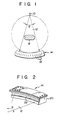
- a fan-shaped distribution of X-ray beam 12 is provided by an X-ray source 10.
- the cross sections of the subject body 18 are given in gradations based on the X-ray absorption factors, thus forming a sectional image.
- the plane sections of the subject body 18 can be analyzed in as many as 2,000 gradations, depending on the composition of the subject body 18.
- a clear sectional image can be obtained for any tissue ranging from soft to hard tissue.
- electrodes as the detecting elements 16, are spacially arranged from one another in a housing 20.
- High-pressure Xe gas is sealed in the housing 20.
- the Xe gas existing in the space is ionized to produce Xe + ions and electrons.
- the Xe + ions and electrons are detected as ionization currents by the electrodes, which are integrated for a predetermined time.
- the integrated currents are discharged by a discharge circuit having a predetermined time constant.
- the intensity of X-ray beam can be calculated from the value of the discharge time.
- the performance of a radiation detector is judged by its sensitivity and resolution (space resolution and density resolution).
- the quality of an image reconstructed on a CT apparatus is influenced by the performance of the radiation detector.
- the sensitivity of the radiation detector is given as the product (atm.cm; hereafter referred to as PL value) of the pressure of gas sealed in the radiation detector and the depth of electrodes.
- the sensitivity is in the vicinity of 60 atm.cm.
- the coefficient of energy absorption ranges from 40 to 60%.
- the space resolution of the radiation detector which depends on the arrangement pitch of the electrodes and focus spot size of X-ray tube, is such that the detector can normally discriminate a substance with a diameter of 0.5 to 0.6 mm.
- the density resolution is related to the capability of distinguishing substances with small differences in density in a subject body. If the radiation detector is higher in density resolution, then it can discriminate smaller differences in density in proportion.
- the density resolution depends on the amount of low-energy photons which are transmitted through the X-ray window of the radiation detector to reach the interelectrode space therein. This is so because definite discrimination of white and gray matter in the subject body requires detection of the low-energy photons, since the difference in the coefficient of X-ray absorption between the white and gray matter is increased in proportion if the energy of the photons is lower.
- the housing 20 of the radiation detector 14 is provided with the X-ray window 22 for the incidence of X-ray beams, which is thinner than any other portion of the housing 20. Also, the housing 20, including the X-ray window 22, is made of aluminium. However, the X-ray window 22 cannot avoid absorption of low-energy photons, failing to provide satisfactory density resolution.
- a radiation detector using a carbon-fibered structure as its X-ray window is disclosed in U.S. Pat. No. 4,260,891.
- a carbon-fibered plate is sandwiched between a pressure vessel and a clamping lid. Therefore, the carbon-fibered plate needs to serve both as the X-ray window and as a sealing gasket between the clamping lid and the pressure vessel.
- this X-ray window is flat in shape.
- the X-ray beam has, generally, fan-shaped distribution, so that the X-ray window is curved around the X-ray source 10 for improved detection accuracy. It is difficult, however, to seal gas at a high pressure of 10 to 30 atm in the housing while keeping the carbon-fibered X-ray window curved. Accordingly, any of prior art radiation detectors is low in practicality.
- the object of the present invention is to improve the radiation detector according to US-A-4260891.
- a radiation detector according to the preamble of claim 1.
- the detector is characterised in that the housing includes a vessel portion in which are arranged the radiation detecting elements the vessel portion having an opening through which the radiation detecting elements are loaded into the housing, a side wall on the side of the center of curvature, a cut in the side wall extending along the longitudinal direction of the housing, and a cover portion covering the opening.
- the radiation window member is curved along and fixed to the inside face of the side wall so as to cover the cut. The window member is also pressed against the inside face of the side wall by the pressure of the gas sealed in the housing.
- the radiation detector of the invention is high in density resolution, and can provide high-quality sectional images when it is incoporated in a CT apparatus.
- the opening through which the radiation detecting elements are loaded into the housing and the cut for the radiation window are provided separately.
- the junction between the cover portion covering the opening and the vessel portion is tightly sealed by the conventional sealing means to prevent leakage of the sealed gas.
- the gas will never leak through the junction between the window member and the vessel portion, since the window member is bonded to the side wall of the vessel portion and is also fixed by means of a reinforcing member as required.
- the window member is pressed against the side wall by the pressure of the sealed gas. Namely, the window member is attached to the housing in a self- sealing manner, so that the junction between the radiation window and the housing can be sealed with improved gastightness.
- the radiation detector according to this invention can hold the gas therein in a fully sealed manner.
- the radiation detector 30 has a housing 32 and an X-ray window 40.
- the housing 32 includes a vessel portion 34 and a cover portion 36.
- the plane configuration of the housing 32 is curved around the X-ray source 10 for providing the fan-shaped distribution of X-ray beam 12 (see Fig. 1). Therefore, the side walls of the vessel portion 34 are curved along the longitudinal direction thereof.
- An elongated rectangular cut 34a, extending along the longitudinal direction of the vessel portion 34, is formed on the side wall of the vessel portion 34 at the center of curvature.
- the cover portion 36 is placed on the top of the vessel portion 34.
- a suitable sealing gasket (not shown) is interposed between the cover portion 36 and the vessel portion 34, and these two portions 36 and 34 are fixed by means of bolts 38.
- the cover and vessel portions 36 and 34 are made of aluminium.
- a plurality of electrodes as X-ray detecting elements are spacially arranged from one another along the longitudinal direction of the housing 32. These electrodes are set in the housing 32, which is fixed to the under surface of the cover portion 36.
- An X-ray window 40 includes a window member 42 and a reinforcing member 44.
- the window member 42 is in the form of the curved plate, matched to the inside face of the side wall of the vessel portion 34 in which the cut 34a is formed.
- the reinforcing member 44 is a plate having substantially the same shape as the window member 42, except that the reinforcing member 44 has a cut 48 in the center which is a little larger than the cut 34a.
- the window member 42 is put on the inside face of its mating side wall of the vessel portion 34 so as to close the cut 34a therein. Further, the reinforcing member 44 is put on the window member 42.
- the reinforcing member 44 is fixed to the inside face of the side wall of the vessel portion 34 by means of bolts 46.
- the peripheral portion of the window member 42 is sandwiched between the side wall of the vessel portion 34 and the reinforcing member 44.
- the bolts 46 are screwed into the side wall of the vessel portion 34 via through holes in the reinforcing member 44 and the window member 42. If the window member 42 is made smaller than the reinforcing member 44, however, it is unnecessary to provide the window member 42 with through holes.
- the window member 42 is made of carbon fiber reinforced plastics (hereafter abbreviated CFRP).
- CFRP carbon fiber reinforced plastics
- the CFRP is formed by heating acrylic fibers or rayon fibers to 200 to 300°C to carbonize the same, then heating them to 700 to 1,800°C for further carbonization, and finally impregnating resultant carbon fibers with resins (e.g., epoxy resins).
- the CFRP usually contains 60% fibers and 40% resins by volume, and has the following properties.
- the X-ray transmission factor of the CFRP is ten times (60 to 100 KV) that of aluminium of the same thickness (same transmission distance).
- the tensile strength of the CFRP in its fiber direction is about 120 kg/mm 2 .
- the CFRP Since the tensile strength of aluminium ranges from 50 to 60 kg/ mm 2 , the CFRP is approximately twice as strong as aluminium. The modulus of elasticity of the CFRP is about 12,000 kg/mm 2 , which is a practical figure. Thus, the CFRP is much higher in X-ray transmission factor and strength than aluminium.
- aluminium foil (not shown) of about 20 pm thickness is put on the convex surface of the curved CFRP plate by adhering aluminium film on the CFRP plate. Since the aluminium foil is electrically conductive, the X-ray window 40 will not be charged even if Xe + ions and electrons produced by ionization of Xe gas in the vessel portion 34 are attached to the inner surface of the X-ray window 40. Impurity gases or outer gases are naturally generated from the CFRP. However, the aluminium foil checks the generation of the outer gases, thereby preventing the outer gases from getting into the inside space of the housing 32.
- the window member 42 is bonded, by means of an adhesive agent such as epoxy resins, to the inside face of the side wall of the vessel portion 34 in which the cut 34a is formed.
- the window member 42 and the side wall of the vessel portion 34 can be bonded together with increased strength by etching the inside face of the side wall to roughen the contact surface to 50 pm or thereabout.
- the window member 42 is pressed against the inside face of the side wall of the vessel portion 34 by the reinforcing member 44.
- Xe gas at a pressure of 10 to 30 atm is sealed in the housing 32.
- the window member 42 is also pressed against the side wall of the vessel portion 34 by the pressure of the sealed gas.
- the window member 42 is sealed and fixed to the side wall by the adhesive agent and the reinforcing member 44, and is also pressed against the side wall by the sealed gas pressure, that is, is self-sealed, so that the gastightness of the housing 32 is very high.
- an X-ray beam passes through the X-ray window 40 formed of CFRP to reach the electrodes (not shown) in the housing 32. Since the CFRP is twice as strong as aluminium, as mentioned before, the thickness of the X-ray window may be made half that of an aluminium X-ray window. Also, the X-ray transmission factor of the CFRP is ten times that of aluminium. Therefore, the amount of X-ray transmission, i.e., the amount of X-rays reaching the electrodes (detecting elements), can be increased, theoretically, about twenty times. Thus, the density resolution is increased. As a result, the signal- to-noise ratio is improved, and the X-ray window absorbs less low-energy X-rays. Accordingly, the radiation detector can positively distinguish white and gray matters which differ little in absorption coefficient.
- Fig. 8 is a graph showing X-ray spectra obtained before and after transmission of X-rays through the X-ray window.
- the axis of abscissa of the graph represents the energy of photons, and the axis of ordinate represents the intensity of X-rays.
- line 50 (solid line) indicates an X-ray absorption spectrum obtained before the transmission through the X-ray window 40;
- line 52 (broken line) indicates an absorption spectrum of X-rays transmitted through the X-ray window made of CFRP, and
- line 54 (dashed line) indicates an absorption spectrum of X-rays transmitted through the X-ray window made of aluminium.
- the spectrum line K-X is not shown in Fig. 8. As seen from Fig.
- the X-ray absorption of the detector on the low-energy side obtained by using the CFRP is 15 to 20% larger than that obtained by using aluminium.
- the X-ray windows used for comparing the results represented by lines 52 and 54 have the same thickness. Since CFRP is higher in strength than aluminium, the X-ray window made of CFRP can be made relatively thin, and can therefore be lowered in X-ray absorption.
- a radiation detector 60 has a housing 32 and an X-ray window 70.
- a curved groove 34b extending along the longitudinal direction of a vessel portion 34 of the housing 32 is formed in the vicinity of a cut 34a in the bottom wall of the vessel portion 34.
- a window member 72 and a reinforcing member 74 are curved around the X-ray source 10.
- the reinforcing member 74 has a cut 78 resembling the cut 48 of the reinforcing member 44.
- a recess 74a in which the window member 72 is fitted is formed in that surface of the reinforcing member 74 which is put on the window member 72, i.e., that surface on the side of the center of curvature.
- the depth of the recess 74a is narrower than the thickness of the window member 72.
- An engaging portion 76 extending along the longitudinal direction of the reinforcing member 74 is formed at the lower end portion thereof.
- That lateral face of the engaging portion 76 on the opposite side to the recess 74a is inclined relative to the bottom wall of the vessel portion 34.
- the cross section of the engaging portion 76 is in the form of a trapezoid with its shorter side downward.
- the engaging portion 76 is fitted in the groove 34b.
- the window member 72 is put on the inside face of that side wall of the vessel portion 34 in which the cut 34a is formed, and the reinforcing member 74 is put on the window member 72 in a manner such that the window member 72 is fitted in the recess 74a, and that the engaging portion 76 is fitted in the groove 34b.
- the frame portion and the engaging portion 76 of the reinforcing member 74 are fixed to the side wall and the bottom wall of the vessel portion 34, respectively, by means of bolts 46.
- the window member 72 is not provided with any holes through which the bolts 46 are passed.
- the X-ray window 70 is free from concentrated stress on the peripheral regions of the holes, and is therefore higher in strength than the X-ray window 40.
- the window member 72 is bonded to the side wall of the vessel portion 34 by means of an adhesive agent. Moreover, the window member 72 is pressed against the side wall of the vessel portion 34 by the pressure of gas sealed in the housing 32, and the engaging portion 76 of the reinforcing member 74 is urged downward by the gas pressure. As a result, the whole structure of the reinforcing member 74 is urged toward the window member 72 by the interaction of the respective slanted surfaces of the engaging portion 76 and the groove 34b. Thus, the window member 72 is brought into closer contact with the side wall of the vessel portion 34 for satisfactory sealing.
Description
- The present invention relates to a radiation detector used in a sectional radiographic apparatus such as a computerized tomographic (hereafter abbreviated as CT) apparatus.
- In a CT apparatus, as shown in Fig. 1, a fan-shaped distribution of
X-ray beam 12 is provided by anX-ray source 10. Aradiation detector 14, comprising a plurality of detectingelements 16 arranged for detecting the intensity of theX-ray beam 12, faces theX-ray source 10 with asubject body 18 between them. While maintaining this positional relation, theX-ray source 10 and theradiation detector 14 are rotated around thesubject body 18. In this state, the intensity of theX-ray beam 12 transmitted through thesubject body 18 in various directions is detected. Detection data obtained in this manner are analyzed by a computer, and X-ray absorption factors for plane sections of thesubject body 18 taken along those different directions are calculated. The cross sections of thesubject body 18 are given in gradations based on the X-ray absorption factors, thus forming a sectional image. In this CT apparatus, the plane sections of thesubject body 18 can be analyzed in as many as 2,000 gradations, depending on the composition of thesubject body 18. Thus, a clear sectional image can be obtained for any tissue ranging from soft to hard tissue. - In the
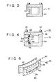
radiation detector 14, as shown in Figs. 1 to 3, electrodes, as thedetecting elements 16, are spacially arranged from one another in ahousing 20. High-pressure Xe gas is sealed in thehousing 20. When theX-ray beam 12 is projected into the interelectrode space on the extension of theX-ray beam 12 through anX-ray window 22 of thehousing 20, the Xe gas existing in the space is ionized to produce Xe+ ions and electrons. The Xe+ ions and electrons are detected as ionization currents by the electrodes, which are integrated for a predetermined time. The integrated currents are discharged by a discharge circuit having a predetermined time constant. The intensity of X-ray beam can be calculated from the value of the discharge time. - The performance of a radiation detector is judged by its sensitivity and resolution (space resolution and density resolution). The quality of an image reconstructed on a CT apparatus is influenced by the performance of the radiation detector. The sensitivity of the radiation detector is given as the product (atm.cm; hereafter referred to as PL value) of the pressure of gas sealed in the radiation detector and the depth of electrodes. Usually, the sensitivity is in the vicinity of 60 atm.cm. In this case, the coefficient of energy absorption ranges from 40 to 60%. The space resolution of the radiation detector, which depends on the arrangement pitch of the electrodes and focus spot size of X-ray tube, is such that the detector can normally discriminate a substance with a diameter of 0.5 to 0.6 mm. The density resolution is related to the capability of distinguishing substances with small differences in density in a subject body. If the radiation detector is higher in density resolution, then it can discriminate smaller differences in density in proportion. The density resolution depends on the amount of low-energy photons which are transmitted through the X-ray window of the radiation detector to reach the interelectrode space therein. This is so because definite discrimination of white and gray matter in the subject body requires detection of the low-energy photons, since the difference in the coefficient of X-ray absorption between the white and gray matter is increased in proportion if the energy of the photons is lower.
- The
housing 20 of theradiation detector 14 is provided with theX-ray window 22 for the incidence of X-ray beams, which is thinner than any other portion of thehousing 20. Also, thehousing 20, including theX-ray window 22, is made of aluminium. However, theX-ray window 22 cannot avoid absorption of low-energy photons, failing to provide satisfactory density resolution. - A radiation detector using a carbon-fibered structure as its X-ray window is disclosed in U.S. Pat. No. 4,260,891. In this radiation detector, a carbon-fibered plate is sandwiched between a pressure vessel and a clamping lid. Therefore, the carbon-fibered plate needs to serve both as the X-ray window and as a sealing gasket between the clamping lid and the pressure vessel. Thus, this X-ray window is flat in shape. In a radiation detector, the X-ray beam has, generally, fan-shaped distribution, so that the X-ray window is curved around the
X-ray source 10 for improved detection accuracy. It is difficult, however, to seal gas at a high pressure of 10 to 30 atm in the housing while keeping the carbon-fibered X-ray window curved. Accordingly, any of prior art radiation detectors is low in practicality. - The object of the present invention is to improve the radiation detector according to US-A-4260891.
- According to the invention, there is provided a radiation detector according to the preamble of claim 1. The detector is characterised in that the housing includes a vessel portion in which are arranged the radiation detecting elements the vessel portion having an opening through which the radiation detecting elements are loaded into the housing, a side wall on the side of the center of curvature, a cut in the side wall extending along the longitudinal direction of the housing, and a cover portion covering the opening. The radiation window member is curved along and fixed to the inside face of the side wall so as to cover the cut. The window member is also pressed against the inside face of the side wall by the pressure of the gas sealed in the housing.
- In this radiation detector, radiation such as an X-ray is transmitted through the window member to be detected by the radiation detecting elements in the housing. Since the X-ray transmission factor of the carbon-fiber-reinforced-plastics is higher than that of aluminium, even low-energy radiation can reach the radiation detecting elements with high intensity. Accordingly, the radiation detector of the invention is high in density resolution, and can provide high-quality sectional images when it is incoporated in a CT apparatus.
- In this radiation detector, moreover, the opening through which the radiation detecting elements are loaded into the housing and the cut for the radiation window are provided separately. The junction between the cover portion covering the opening and the vessel portion is tightly sealed by the conventional sealing means to prevent leakage of the sealed gas. The gas will never leak through the junction between the window member and the vessel portion, since the window member is bonded to the side wall of the vessel portion and is also fixed by means of a reinforcing member as required. The window member is pressed against the side wall by the pressure of the sealed gas. Namely, the window member is attached to the housing in a self- sealing manner, so that the junction between the radiation window and the housing can be sealed with improved gastightness. Thus, the radiation detector according to this invention can hold the gas therein in a fully sealed manner.
- This invention can be more fully understood from the following detailed description when taken in conjunction with the accompanying drawings, in which:
- Fig. 1 is a schematic plan view of a CT apparatus;
- Fig. 2 is a perspective view of a conventional radiation detector;
- Fig. 3 is a sectional view of the radiation detector of Fig. 2;
- Fig. 4 is a sectional view of a radiation detector according to one embodiment of the present invention;
- Fig. 5 is a disassembled perspective view of an X-ray window of the radiation detector of Fig. 4;
- Fig. 6 is a sectional view of a radiation detector according to another embodiment of the invention;
- Fig. 7 is a partial disassembled perspective view of an X-ray window of the radiation detector of Fig. 6; and
- Fig. 8 is a graph showing effects of the invention.
- Referring now to the drawings of Figs. 4 and 5, there is shown a
radiation detector 30 according to one embodiment of the present invention. Theradiation detector 30 has ahousing 32 and anX-ray window 40. Thehousing 32 includes avessel portion 34 and acover portion 36. As in the priorart radiation detector 14, the plane configuration of thehousing 32 is curved around theX-ray source 10 for providing the fan-shaped distribution of X-ray beam 12 (see Fig. 1). Therefore, the side walls of thevessel portion 34 are curved along the longitudinal direction thereof. An elongated rectangular cut 34a, extending along the longitudinal direction of thevessel portion 34, is formed on the side wall of thevessel portion 34 at the center of curvature. Thecover portion 36 is placed on the top of thevessel portion 34. A suitable sealing gasket (not shown) is interposed between thecover portion 36 and thevessel portion 34, and these twoportions bolts 38. The cover andvessel portions housing 32. These electrodes are set in thehousing 32, which is fixed to the under surface of thecover portion 36. - An
X-ray window 40 includes awindow member 42 and a reinforcingmember 44. Thewindow member 42 is in the form of the curved plate, matched to the inside face of the side wall of thevessel portion 34 in which the cut 34a is formed. The reinforcingmember 44 is a plate having substantially the same shape as thewindow member 42, except that the reinforcingmember 44 has acut 48 in the center which is a little larger than the cut 34a. Thewindow member 42 is put on the inside face of its mating side wall of thevessel portion 34 so as to close the cut 34a therein. Further, the reinforcingmember 44 is put on thewindow member 42. The reinforcingmember 44 is fixed to the inside face of the side wall of thevessel portion 34 by means ofbolts 46. Thus, the peripheral portion of thewindow member 42 is sandwiched between the side wall of thevessel portion 34 and the reinforcingmember 44. In the example shown in Figs. 4 and 5, thebolts 46 are screwed into the side wall of thevessel portion 34 via through holes in the reinforcingmember 44 and thewindow member 42. If thewindow member 42 is made smaller than the reinforcingmember 44, however, it is unnecessary to provide thewindow member 42 with through holes. - The
window member 42 is made of carbon fiber reinforced plastics (hereafter abbreviated CFRP). The CFRP is formed by heating acrylic fibers or rayon fibers to 200 to 300°C to carbonize the same, then heating them to 700 to 1,800°C for further carbonization, and finally impregnating resultant carbon fibers with resins (e.g., epoxy resins). The CFRP usually contains 60% fibers and 40% resins by volume, and has the following properties. The X-ray transmission factor of the CFRP is ten times (60 to 100 KV) that of aluminium of the same thickness (same transmission distance). The tensile strength of the CFRP in its fiber direction is about 120 kg/mm2. Since the tensile strength of aluminium ranges from 50 to 60 kg/ mm2, the CFRP is approximately twice as strong as aluminium. The modulus of elasticity of the CFRP is about 12,000 kg/mm2, which is a practical figure. Thus, the CFRP is much higher in X-ray transmission factor and strength than aluminium. - In this embodiment, aluminium foil (not shown) of about 20 pm thickness is put on the convex surface of the curved CFRP plate by adhering aluminium film on the CFRP plate. Since the aluminium foil is electrically conductive, the
X-ray window 40 will not be charged even if Xe+ ions and electrons produced by ionization of Xe gas in thevessel portion 34 are attached to the inner surface of theX-ray window 40. Impurity gases or outer gases are naturally generated from the CFRP. However, the aluminium foil checks the generation of the outer gases, thereby preventing the outer gases from getting into the inside space of thehousing 32. - The
window member 42 is bonded, by means of an adhesive agent such as epoxy resins, to the inside face of the side wall of thevessel portion 34 in which the cut 34a is formed. In this case, thewindow member 42 and the side wall of thevessel portion 34 can be bonded together with increased strength by etching the inside face of the side wall to roughen the contact surface to 50 pm or thereabout. As described above, thewindow member 42 is pressed against the inside face of the side wall of thevessel portion 34 by the reinforcingmember 44. Also, Xe gas at a pressure of 10 to 30 atm is sealed in thehousing 32. Thewindow member 42 is also pressed against the side wall of thevessel portion 34 by the pressure of the sealed gas. Thus, thewindow member 42 is sealed and fixed to the side wall by the adhesive agent and the reinforcingmember 44, and is also pressed against the side wall by the sealed gas pressure, that is, is self-sealed, so that the gastightness of thehousing 32 is very high. - In this radiation detector, an X-ray beam passes through the
X-ray window 40 formed of CFRP to reach the electrodes (not shown) in thehousing 32. Since the CFRP is twice as strong as aluminium, as mentioned before, the thickness of the X-ray window may be made half that of an aluminium X-ray window. Also, the X-ray transmission factor of the CFRP is ten times that of aluminium. Therefore, the amount of X-ray transmission, i.e., the amount of X-rays reaching the electrodes (detecting elements), can be increased, theoretically, about twenty times. Thus, the density resolution is increased. As a result, the signal- to-noise ratio is improved, and the X-ray window absorbs less low-energy X-rays. Accordingly, the radiation detector can positively distinguish white and gray matters which differ little in absorption coefficient. - Fig. 8 is a graph showing X-ray spectra obtained before and after transmission of X-rays through the X-ray window. The axis of abscissa of the graph represents the energy of photons, and the axis of ordinate represents the intensity of X-rays. In Fig. 8, line 50 (solid line) indicates an X-ray absorption spectrum obtained before the transmission through the
X-ray window 40; line 52 (broken line) indicates an absorption spectrum of X-rays transmitted through the X-ray window made of CFRP, and line 54 (dashed line) indicates an absorption spectrum of X-rays transmitted through the X-ray window made of aluminium. The spectrum line K-X is not shown in Fig. 8. As seen from Fig. 8, the X-ray absorption of the detector on the low-energy side obtained by using the CFRP is 15 to 20% larger than that obtained by using aluminium. The X-ray windows used for comparing the results represented bylines 52 and 54 have the same thickness. Since CFRP is higher in strength than aluminium, the X-ray window made of CFRP can be made relatively thin, and can therefore be lowered in X-ray absorption. - Referring now to Figs. 6 and 7, another embodiment of the invention will be described. This embodiment differs from the first embodiment only in the construction of the X-ray window. In Figs. 6 and 7, like reference numerals are used to designate like members included in the first embodiment, and description of those members is omitted. A
radiation detector 60 according to this second embodiment has ahousing 32 and anX-ray window 70. Acurved groove 34b extending along the longitudinal direction of avessel portion 34 of thehousing 32 is formed in the vicinity of a cut 34a in the bottom wall of thevessel portion 34. - Like the
window member 42 and the reinforcingmember 44, awindow member 72 and a reinforcingmember 74 are curved around theX-ray source 10. The reinforcingmember 74 has acut 78 resembling thecut 48 of the reinforcingmember 44. A recess 74a in which thewindow member 72 is fitted is formed in that surface of the reinforcingmember 74 which is put on thewindow member 72, i.e., that surface on the side of the center of curvature. The depth of the recess 74a is narrower than the thickness of thewindow member 72. An engagingportion 76 extending along the longitudinal direction of the reinforcingmember 74 is formed at the lower end portion thereof. That lateral face of the engagingportion 76 on the opposite side to the recess 74a is inclined relative to the bottom wall of thevessel portion 34. Thus, the cross section of the engagingportion 76 is in the form of a trapezoid with its shorter side downward. The engagingportion 76 is fitted in thegroove 34b. Thewindow member 72 is put on the inside face of that side wall of thevessel portion 34 in which the cut 34a is formed, and the reinforcingmember 74 is put on thewindow member 72 in a manner such that thewindow member 72 is fitted in the recess 74a, and that the engagingportion 76 is fitted in thegroove 34b. The frame portion and the engagingportion 76 of the reinforcingmember 74 are fixed to the side wall and the bottom wall of thevessel portion 34, respectively, by means ofbolts 46. In this embodiment, thewindow member 72 is not provided with any holes through which thebolts 46 are passed. Thus, theX-ray window 70 is free from concentrated stress on the peripheral regions of the holes, and is therefore higher in strength than theX-ray window 40. - Also in this embodiment, the
window member 72 is bonded to the side wall of thevessel portion 34 by means of an adhesive agent. Moreover, thewindow member 72 is pressed against the side wall of thevessel portion 34 by the pressure of gas sealed in thehousing 32, and the engagingportion 76 of the reinforcingmember 74 is urged downward by the gas pressure. As a result, the whole structure of the reinforcingmember 74 is urged toward thewindow member 72 by the interaction of the respective slanted surfaces of the engagingportion 76 and thegroove 34b. Thus, thewindow member 72 is brought into closer contact with the side wall of thevessel portion 34 for satisfactory sealing.
Claims (10)
Applications Claiming Priority (2)
| Application Number | Priority Date | Filing Date | Title |
|---|---|---|---|
| JP89195/83 | 1983-05-23 | ||
| JP58089195A JPS59216075A (en) | 1983-05-23 | 1983-05-23 | Radiation detector |
Publications (3)
| Publication Number | Publication Date |
|---|---|
| EP0127074A2 EP0127074A2 (en) | 1984-12-05 |
| EP0127074A3 EP0127074A3 (en) | 1985-06-19 |
| EP0127074B1 true EP0127074B1 (en) | 1987-11-25 |
Family
ID=13963929
Family Applications (1)
| Application Number | Title | Priority Date | Filing Date |
|---|---|---|---|
| EP84105595A Expired EP0127074B1 (en) | 1983-05-23 | 1984-05-16 | Radiation detector |
Country Status (4)
| Country | Link |
|---|---|
| US (1) | US4617465A (en) |
| EP (1) | EP0127074B1 (en) |
| JP (1) | JPS59216075A (en) |
| DE (1) | DE3467830D1 (en) |
Families Citing this family (8)
| Publication number | Priority date | Publication date | Assignee | Title |
|---|---|---|---|---|
| FR2623940A1 (en) * | 1987-11-27 | 1989-06-02 | Commissariat Energie Atomique | RADIATION DETECTOR AND METHOD FOR MANUFACTURING ITS INPUT WINDOW |
| US5095217A (en) * | 1990-10-17 | 1992-03-10 | Wisconsin Alumni Research Foundation | Well-type ionization chamber radiation detector for calibration of radioactive sources |
| US5426305A (en) * | 1994-08-26 | 1995-06-20 | The United States Of America As Represented By The Secretary Of The Army | Hermetically sealed plastic radiation detector |
| WO2013159049A1 (en) | 2012-04-20 | 2013-10-24 | Bruker Axs Handheld, Inc. | Apparatus for protecting a radiation window |
| JP2014160040A (en) * | 2013-02-20 | 2014-09-04 | Toshiba Corp | X-ray transmission apparatus and x-ray inspection apparatus |
| DE102013215413A1 (en) * | 2013-08-06 | 2015-02-12 | Siemens Aktiengesellschaft | Ray window |
| EP3599631A1 (en) * | 2018-07-27 | 2020-01-29 | Moxtek, Inc. | Mounted x-ray window |
| CN115266776B (en) * | 2022-09-15 | 2023-05-09 | 深圳市伟铭光电有限公司 | Nondestructive testing device for X-ray steel cylinder |
Family Cites Families (8)
| Publication number | Priority date | Publication date | Assignee | Title |
|---|---|---|---|---|
| GB1495259A (en) * | 1974-11-15 | 1977-12-14 | Fulmer Res Inst Ltd | Gas containers |
| US4031396A (en) * | 1975-02-28 | 1977-06-21 | General Electric Company | X-ray detector |
| GB2027262A (en) * | 1978-08-04 | 1980-02-13 | Emi Ltd | Onisation chambers |
| US4276476A (en) * | 1978-12-20 | 1981-06-30 | General Electric Company | Radiation detector having a unitary free floating electrode assembly |
| JPS5717879A (en) * | 1980-07-07 | 1982-01-29 | Toshiba Chem Corp | Manufacture of x ray transmission pressure container |
| JPS5749879A (en) * | 1980-09-10 | 1982-03-24 | Toshiba Corp | Detector for radiation |
| US4414473A (en) * | 1981-02-23 | 1983-11-08 | General Electric Company | Resilient mount for modular detector cell |
| FR2505492B1 (en) * | 1981-05-06 | 1985-11-08 | Commissariat Energie Atomique |
-
1983
- 1983-05-23 JP JP58089195A patent/JPS59216075A/en active Granted
-
1984
- 1984-05-16 US US06/610,695 patent/US4617465A/en not_active Expired - Lifetime
- 1984-05-16 DE DE8484105595T patent/DE3467830D1/en not_active Expired
- 1984-05-16 EP EP84105595A patent/EP0127074B1/en not_active Expired
Also Published As
| Publication number | Publication date |
|---|---|
| DE3467830D1 (en) | 1988-01-07 |
| EP0127074A3 (en) | 1985-06-19 |
| US4617465A (en) | 1986-10-14 |
| JPH0479433B2 (en) | 1992-12-15 |
| JPS59216075A (en) | 1984-12-06 |
| EP0127074A2 (en) | 1984-12-05 |
Similar Documents
| Publication | Publication Date | Title |
|---|---|---|
| US4161655A (en) | Multi-cell detector using printed circuit board | |
| RU2147138C1 (en) | Gas-ionization matrix detector for radiographic analyses | |
| US4047041A (en) | X-ray detector array | |
| EP0127074B1 (en) | Radiation detector | |
| US4306155A (en) | Gas-filled x-ray detector with improved window | |
| US4075527A (en) | X-ray detector | |
| JP2008534950A (en) | Radiation detection apparatus, radiation detection apparatus manufacturing method, radiation detection method, window, and radiation detection apparatus window manufacturing method | |
| US4376893A (en) | Ion chamber array with reduced dead space | |
| GB1601580A (en) | Tomographic imaging system | |
| US4859855A (en) | Dosimeter for ionizing radiation | |
| US4260891A (en) | Radiation detectors | |
| US4481420A (en) | Process for the manufacturing of X-ray detectors for use in tomography, radiography, and the like | |
| EP0748456B1 (en) | Polyethylene naphtalate x-ray window | |
| US4866744A (en) | Scattering beam eliminating device for x-ray CT apparatus | |
| US4477728A (en) | Radiation detector | |
| US4625117A (en) | Multi-cell radiation detector | |
| JPH0130116B2 (en) | ||
| US4136282A (en) | Directional detector of gamma rays | |
| JPH0259582B2 (en) | ||
| GB1561007A (en) | Ray detectors | |
| US4475043A (en) | Xenon x-ray detector with tapered plates | |
| GB1600440A (en) | Multi-channel x-ray detector | |
| Baru et al. | One dimensional X-ray MSGC detector for synchrotron radiation experiments and medical imaging | |
| JPS6252423B2 (en) | ||
| JP2005257598A (en) | X-ray ion chamber detector |
Legal Events
| Date | Code | Title | Description |
|---|---|---|---|
| PUAI | Public reference made under article 153(3) epc to a published international application that has entered the european phase |
Free format text: ORIGINAL CODE: 0009012 |
|
| 17P | Request for examination filed |
Effective date: 19840613 |
|
| AK | Designated contracting states |
Designated state(s): DE FR GB NL |
|
| PUAL | Search report despatched |
Free format text: ORIGINAL CODE: 0009013 |
|
| AK | Designated contracting states |
Designated state(s): DE FR GB NL |
|
| 17Q | First examination report despatched |
Effective date: 19870218 |
|
| GRAA | (expected) grant |
Free format text: ORIGINAL CODE: 0009210 |
|
| AK | Designated contracting states |
Kind code of ref document: B1 Designated state(s): DE FR GB NL |
|
| REF | Corresponds to: |
Ref document number: 3467830 Country of ref document: DE Date of ref document: 19880107 |
|
| ET | Fr: translation filed | ||
| PLBE | No opposition filed within time limit |
Free format text: ORIGINAL CODE: 0009261 |
|
| STAA | Information on the status of an ep patent application or granted ep patent |
Free format text: STATUS: NO OPPOSITION FILED WITHIN TIME LIMIT |
|
| 26N | No opposition filed | ||
| PGFP | Annual fee paid to national office [announced via postgrant information from national office to epo] |
Ref country code: GB Payment date: 19970507 Year of fee payment: 14 |
|
| PGFP | Annual fee paid to national office [announced via postgrant information from national office to epo] |
Ref country code: FR Payment date: 19970513 Year of fee payment: 14 |
|
| PG25 | Lapsed in a contracting state [announced via postgrant information from national office to epo] |
Ref country code: GB Free format text: LAPSE BECAUSE OF NON-PAYMENT OF DUE FEES Effective date: 19980516 |
|
| PG25 | Lapsed in a contracting state [announced via postgrant information from national office to epo] |
Ref country code: FR Free format text: LAPSE BECAUSE OF NON-PAYMENT OF DUE FEES Effective date: 19980531 |
|
| PGFP | Annual fee paid to national office [announced via postgrant information from national office to epo] |
Ref country code: NL Payment date: 19980531 Year of fee payment: 15 |
|
| GBPC | Gb: european patent ceased through non-payment of renewal fee |
Effective date: 19980516 |
|
| REG | Reference to a national code |
Ref country code: FR Ref legal event code: ST |
|
| PG25 | Lapsed in a contracting state [announced via postgrant information from national office to epo] |
Ref country code: NL Free format text: LAPSE BECAUSE OF NON-PAYMENT OF DUE FEES Effective date: 19991201 |
|
| NLV4 | Nl: lapsed or anulled due to non-payment of the annual fee |
Effective date: 19991201 |
|
| PGFP | Annual fee paid to national office [announced via postgrant information from national office to epo] |
Ref country code: DE Payment date: 20030529 Year of fee payment: 20 |