EP0126800B1 - An automatic, continuous method for producing a panty-hose and a panty-hose closer used therefor - Google Patents
An automatic, continuous method for producing a panty-hose and a panty-hose closer used therefor Download PDFInfo
- Publication number
- EP0126800B1 EP0126800B1 EP19830105383 EP83105383A EP0126800B1 EP 0126800 B1 EP0126800 B1 EP 0126800B1 EP 19830105383 EP19830105383 EP 19830105383 EP 83105383 A EP83105383 A EP 83105383A EP 0126800 B1 EP0126800 B1 EP 0126800B1
- Authority
- EP
- European Patent Office
- Prior art keywords
- panty
- hose
- incomplete
- closer
- suction
- Prior art date
- Legal status (The legal status is an assumption and is not a legal conclusion. Google has not performed a legal analysis and makes no representation as to the accuracy of the status listed.)
- Expired
Links
- 238000011437 continuous method Methods 0.000 title claims description 5
- 230000000712 assembly Effects 0.000 claims description 9
- 238000000429 assembly Methods 0.000 claims description 9
- 210000003371 toe Anatomy 0.000 description 60
- 238000004519 manufacturing process Methods 0.000 description 9
- 238000000034 method Methods 0.000 description 4
- 238000009958 sewing Methods 0.000 description 4
- 230000007306 turnover Effects 0.000 description 4
- 238000004826 seaming Methods 0.000 description 3
- 238000004891 communication Methods 0.000 description 2
- 238000010276 construction Methods 0.000 description 2
- NJPPVKZQTLUDBO-UHFFFAOYSA-N novaluron Chemical compound C1=C(Cl)C(OC(F)(F)C(OC(F)(F)F)F)=CC=C1NC(=O)NC(=O)C1=C(F)C=CC=C1F NJPPVKZQTLUDBO-UHFFFAOYSA-N 0.000 description 2
- 230000015572 biosynthetic process Effects 0.000 description 1
- 238000010924 continuous production Methods 0.000 description 1
- 230000013011 mating Effects 0.000 description 1
- 238000002360 preparation method Methods 0.000 description 1
Images





Classifications
-
- D—TEXTILES; PAPER
- D05—SEWING; EMBROIDERING; TUFTING
- D05B—SEWING
- D05B23/00—Sewing apparatus or machines not otherwise provided for
- D05B23/007—Sewing units for assembling parts of knitted panties or closing the stocking toe part
Definitions
- the present invention relates to an automatic continuous method for producing a panty-hose on a panty-hose closer which includes a panty closer assembly provided with a plurality of clamp holder units circulating along an endless first path of travel, a toe closer assembly provided with a plurality of suction holder units circulating along an endless second path of travel, and a transferer assembly arranged at a junction between the panty closer and toe closer assemblies.
- an automatic continuous panty-hose closer comprising a panty-hose closer assembly which includes a plurality of clamp holder units arranged for circulation along an endless first path of travel and is adapted for closing the panty section of a material panty-hose to form a incomplete panty-hose during the circulation of the clamp holder units, a toe closer assembly which includes a plurality of suction holder units arranged for circulation along an endless second path of travel and is adapted for closing the toe ends of the incomplete panty-hose to form a complete panty-hose during the circulation of the suction holder units, and a transferer assembly arranged at a junction between the panty closer and the toe closer assemblies.
- panty closer is described in US-A-3 777 681, and one example of such a toe closer is described in US-A-4 133 280.
- Panty-hose closers are also known from US-A-3 520 262, GB-A-2 081 316, GB-A-2 103 257, and FR-A-2 415 684.
- panty and toe closers are usually built as separate machines and usually a panty-hose production mill is equipped with a number of panty and toe closers.
- One closer requires one operator and additional operators are required for transportation of incomplete panty-hoses between panty and toe closers.
- an incomplete panty-hose refers to a material panty-hose with a closed panty section when closing of the panty section comes first, and to a material panty-hose with closed toe ends when closing of the toe ends precedes.
- transportation of incomplete panty-hoses between panty and toe closers is highly labour and time consumptive, thereby seriously lowering efficiency in production of panty-hoses.
- the method is carried out by mechanically holding one incomplete panty-hose on one clamp holder unit in a laterally spread state in which the sew line on its closed panty section should be substantially in line with the first path of travel of the clamp holder units and its open leg sections should be separately left free, seizing, while keeping the laterally spread state, the leg sections into a pair of successive suction holder units by application of pneumatic suction at the junction, releasing the incomplete panty-hose from the mechanical hold by the clamp holder unit while keeping the laterally spread state, catching the panty section of the incomplete panty-hose by the transferer assembly, and inserting the closed panty section of the incomplete panty-hose inside out over the suction holder units by reciprocation of the transferer assembly for fully automatic transfer of the incomplete panty-hose from the
- the panty-hose closer is characterized in that the junction is taken facing a station on the first path of travel for the clamp holder units whereat the incomplete panty-hose is mechanically held in a laterally spread state in which the sew line on its closed panty section is substantially in line with the first path of travel, that leg sections of the spread incomplete panty-hose held by the clamp unit in a free state are pneumatically seized separately by a pair of successive suction holder units arriving at the junction, that the transferer assembly catches the spread panty section of the incomplete panty-hose, that the clamp holder unit thereafter releases the spread incomplete panty-hose from its mechanical hold, and that the transferer assembly inserts the panty section of the incomplete panty-hose inside out over the suction holder units by its reciprocation for automatic transfer of the incomplete panty-hose from the panty closer to toe closer assembly.
- panty-hose closer in accordance with the present invention is shown in Fig. 1, in which the panty-hose closer includes a panty closer assembly P for closing the panty sections of an incomplete panty-hose, a toe closer assembly T arranged next to the panty closer section P and for closing toes in the leg sections of the incomplete panty-hose and a transferer assembly 50 arranged facing the junction between the panty and toe closer assemblies P and T for periodical transfer of each incomplete panty-hose from the panty closer to toe closer assembly T.
- a panty closer assembly P for closing the panty sections of an incomplete panty-hose
- toe closer assembly T arranged next to the panty closer section P and for closing toes in the leg sections of the incomplete panty-hose
- transferer assembly 50 arranged facing the junction between the panty and toe closer assemblies P and T for periodical transfer of each incomplete panty-hose from the panty closer to toe closer assembly T.
- the panty closer assembly P includes an endless, substantially horizontal guide rail 11 which defines, in the case of the illustrated embodiment, a circular path of travel.
- a flat, circular carrier 12 is slidably coupled to the guide rail 11 and holds, via support arms 14, a substantially horizontal, circular guide pipe 13 which is larger in diameter than the above-described guide rail 11.
- a plurality of clamp holder units 20 are arranged on the carrier 12 at substantially equal intervals for movement along the above-described path of travel as the carrier 12 rotates.
- the panty closer assembly P includes six sets of clamp holder units 20 of same construction.
- FIG. 2 One embodiment of the above-described clamp holder unit 20 is illustrated in Fig. 2, in which the clamp holder unit 20 is provided with a pair of support arms 23 and 24 swingably mounted, at their proximal ends, to a common vertical shaft 25.
- One support arm 23 carries, at its distal end, a pair of upper and lower clampers 21 a and 21 b whereas the other support arm 24 carries at its distal end a pair of upper and lower clampers 22a and 22b.
- the clampers 21a a and 21b are located substantially in parallel to the clampers 22a and 22b directed radially normal to the above-described path of travel for the clamp holder units 20.
- the clampers 21a a and 21b are located substantially in alignment with the clampers 22a and 22b and directed along the above-described path of travel for the clamp holder units 20. Further, in each pair, the upper and lower clampers 21 a and 21 b (or 22a and 22b) are movable to and from each other so that they can apply, in pressure contact with each other, a clamp on the panty section of an incomplete panty-hose mounted to the associated clamp holder unit 20.
- Each clamp holder unit 20 travels, together with the carrier 12 and the guide pipe 13, in a direction shown with an arrow "a" in Fig. 1 in order to be sequentially registered at one of six work stations A to F taken along the above-described path of travel at equal intervals. Since the panty closer unit P in the illustrated embodiment includes six sets of clamp holder units 20, each of the six work stations A to F are occupied by one of the six sets of clamp holder units 20.
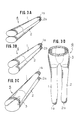
- a material panty-hose 4 includes a pair of leg sections 1 and 2 with toe ends 1 a and 2a still open and connected to each other at a section above the crotch which is later formed into a panty section 3 shown in Fig. 3C.
- a material panty-hose 4 such as shown in Fig. 3A is mounted to each clamp holder unit 20 of the panty closer assembly P in such a mannerthat one leg section 1 should be inserted over the upper clampers 21a a and 22a whereas the other leg section 2 should be inserted over the lower clampers 21 b and 22b.
- the leg sections 1 and 2 of the material panty-hose hang outside from the guide pipe 13.
- a cutter unit 16 is arranged centrally of the path of travel for the clamp holder units 20 and turns about its inner end in sychronism with the mov- ment of the carrier 12. As the clamp holder unit 20 travels from the second work station B to the third work station C, the cutter unit 16 turns in the same direction and forms a cut in the crotch of the material panty-hose 4 as shown in Fig. 38. After formation of this cut, the arms 23 and 24 swing away from each other about the support shaft 25 so that the clampers 21a, 21 b, 22a and 22b are aligned in the direction of the circular path of travel for the clamp holder units 20 and the cut edges should be exposed towards the center of the circular path of travel.
- a sewing machine 17 is arranged whilst facing from the inner side the circular path of travel for the clamp holder units 20.
- the clamp holder unit 20 travels from the fourth work station Dtothefifth work station E, the upper and lower cut edges in the material panty-hose 4 are shown together by the sewing machine 17 in order to form an incomplete panty-hose 5 shown in Fig. 3C which includes a panty section 3 and a pair of leg sections 1 and 2 with toe ends 1 a and 1 stiff open.
- the support arms 23 and 24 swing towards each other about the shaft 25 so that the clampers 21a, 21 b, 22a and 22b are again directed radially normal to the circular path of travel for the clamp holder units 20.
- the toe closer assembly T is arranged facing the fifth work station E of the panty closer assembly P. More specifically, the toe closer assembly T is arranged so that, when a clamp holder unit 20 with an incomplete panty-hose 5 of the panty closer assembly P arrives at the fifth work station E, at least two of suction holder units 30 of the toe closer assembly T should be located facing the clamp holder unit 20 of the panty closer assembly P. Before the moment whereat the two suction holder units 30 face the clamp holder unit 20, the two leg sections 1 and 2 of the incomplete panty-hose 5 held by the clamp holder unit 20 and hanging down from the guide pipe 13 are separately caught by these suction holder units 30.
- suction at the suction holder units 30 should preferably be generated when the leg sections 1 and 2 come closest to the suction ends of the suction holder units 30.
- suction holder units 30 one leg section 1 held by the upper clampers 21a and 22a of the clamp holder unit 20 is caught by the preceding suction holder unit 30 and the other leg section 2 held by the lower clampers 21b and 22b of the clamp holder unit 20 is caught by the following suction holder unit 30.
- the toe closer assembly 50 is shown in detail in Figs. 1, 4 and 5.
- a pair of spaced, oval frames 32 are mounted to the front side, i.e. the side facing the panty closer assembly P, of a magazine 31.
- the frames 32 both extend vertically and substantially in parallel to each other in order to define an oval path of travel for the suction holder units 30.
- 16 sets of suction holder units 30 are arranged along the oval path of travel at substantially equal intervals.
- eight work stations I to VIII are taken on the oval path of travel for operations to be applied to an incomplete panty-hose 5 carried by each pair of suction holder units 30.
- Each suction holder units 30 includes a suction tube 34 having a front suction head 33 and directed substantially normal to the oval path of travel for the suction holder units 30, and intermediate and rear sliders 35 and 36 slidably coupled to the suction tube 34. It further includes a pair of finger plates 37 and 38 which are slidably complied to guide grooves formed in both lateral sides of the suction head 33 and extend along the suction tube 34. These finger plates 37 and 38 are pivoted at their bodies to the intermediate slider 35.
- the rear slider 36 carries a circular disc 39 used for opening and closing the front ends of the finger plates 37 and 38. That is the front ends are opened upon rotation of the circular disc 39 in one direction and are closed upon rotation of the 39 in the other direction.
- the finger plates 37 and 38, the intermediate slider 35 and the rear slider 36 form a unit which is movable to and from the suction head 33 along the suction tube 34.
- the suction holder units 30 are arranged along the oval path of travel defined between the pair of frames 32 and driven for intermittent movement in a direction shown with an arrow "b" in Fig. 4.
- Eight work stations I to VIII are taken along the oval path of travel for prescribed operations to be applied to an incomplete panty-hose 5 carried by each suction holder unit 30.
- a first suction unit 40 is arranged facing the rear ends of the suction holder units 30 passing by whilst extending from the first to second work station II as shown in Fig. 5 so that the suction tubes 34 of the suction holder units 30 travelling through this area are brought into pneumatic communication with the suction unit 40.
- the suction holder units 30 come to the second work station II and face the clamp holder unit 20 still holding the panty section 3 of the incomplete panty-hose 5.
- the clamp holder unit 20 cancels its hold on the incomplete panty-hose 5 and, as already described, the panty section 3 is inserted inside out over the two suction holder units 30 by operation of the transferer assembly 50.
- the incomplete panty-hose 5 is fully transferred from the panty closer assembly P to the toe closer assembly T by assistance of the transferer assembly 50.
- a pair of turn-over rollers 41 and 42 are arranged for contact with the panty section 3 of the incomplete panty-hose 5 brought to this station.
- the turn-over rollers 41 and 42 rotate, the panty section 3 is moved rearwards so that the panty section 3 and the leg sections 1 and 2 should fully be inserted inside out over the two suction holder units 30.
- the toe ends 1a and 1b of the incomplete panty-hose 5 in this state are located near the front suction ends 33 of the suction holder units 30.
- Heel and toe position adjustments are conditionally carried at the fourth and fifth work stations IV and V.
- the heel end has to be located on the associated suction holder unit 30 so that it should come into exact alignment with the seam line of the associated toe end.
- a pair of heel adjusters 43 are arranged at the fourth work station IV and a pair of toe adjusters 44 are arranged at the fifth work station V.
- Any conventional adjusters are usable for this purpose.
- One example of such an adjuster includes a photoelectric sensor, a comparator circuit, a pulse motor electrically connected to the comparator circuit, and and adjuster roller which is driven for rotation by the pulse motor and arranged for contact with an incomplete panty-hose 5 on the suction holder unit 30.
- the photoelectric sensor detects the actual position of, for example, the toe end with respect to the front suction head 33 of the associated suction holder unit 30 and generates a corresponding actual position signal
- the comparator circuit compares this actual position signal with a reference position signal which represents the correct position of the toe with respect to the above-described front suction head 33, and generates an operation signal corresponding to the difference between the actual and reference position signals.
- the pulse motor drive the adjuster roller over a period enough to bring the toe end to the correct position represented by the above-described reference position signal. It should be understood by one skilled in the art that the position adjustments at the fourth and fifth work stations IV and V are both carried out only when the difference is obtained in the comparator circuit.
- the incomplete panty-hose 5 carried by the suction holder units 30 is brought to the sixth work station VI.
- a plate cam 45 is secured horizontally to the rear side frame 32 at a level able to come into contact with the circular disc 39 of each suction holder unit 30 passing by.
- the finger plates 37 and 38 of the suction holder unit 30 swing horizontally outwards from each other in order to laterally spread the toe ends 1 a and 1 b of the leg section 1 on the suction holder unit 30. Further, the finger plates 37 and 38 with the spreaded toe ends 1 a and 2a moves forwards for toe seaming preparation.
- a sewing machine 46 is arranged at the seventh work station VIII facing the front suction head 33 of the suction holder unit 30 passing by.
- the spread toe ends 1 a and 1b are closed by seaming by the sewing machine 46 in order to obtain a complete panty-hose 6 shown in Fig. 3D, in which the complete panty-hose 6 includes a closed panty section 3 and a pair of toe closed leg sections 1 and 2.
- the finger plates 37 and 38 swing towards each other and recede in order to cancel the spreaded state of the toe ends 1a and 2a.
- a second suction unit 47 is arranged facing the rear ends of the suction holder units 30 passing by in the area of the eight work station VIII so that the suction tubes 34 of the suction holder units 30 travelling through this area are brought into pneumatic communication with the suction unit 47.
- this suction unit 47 By operation of this suction unit 47, the leg sections 1 and 2 of the complete panty-hose 6 on the suction holder units 30 are sucked into the respective suction tubes 34.
- a pair of turn-over rollers 48 are arranged at this work station VIII in order to again turn over the complete panty-hose 6 concurrently with the suction by the suction tubes 34. After the complete panty-hose 6 is fully turned over on the suction holder unit 30, the suction by the second suction unit 47 is cancelled.
- a funnel shaped suction pipe 49 is arranged at the eighth work station VIII facing the front sucking head 33 of each suction holder unit 30 passing by.
- each incomplete panty-hose 5 is passed from the panty closer assembly P over to the toe closer assembly T by operation of the transferer assembly 50.
- One embodiment of the transfer assembly 50 is shown in Figs. 6 to 8.
- the transferer assembly 50 is attached to the magazine 31 to the toe closer assembly T whilst extending across the oval path of travel for the suction holder units 30.
- the transferer assembly 50 includes an elongated bracket 51 is secured to the side of the magazine and extends towards the panty closer assembly P.
- a pair of upper and lower guides 52 and 53 are horizontally mounted to the bracket 51 and both extend in parallel to each other in the longitudinal direction of the bracket 51. These guides 52 and 53 carry a slide head 54 which reciprocates along them.
- a pair of sprocket wheels 55 and 56 are rotatably mounted to the bracket 51 being horizontally spaced from each other in order to carry an endless chain 58.
- the sprocket wheels 55 and 56 are driven for rotation by a drive motor 57 operationally coupled to the sprocket wheel 55 via a suitable reduction gear.
- a guide roller 59 is secured to one link of the endless chain 58 and engages with a vertical groove 54a formed on the mating side of the slide head 54 on the guides 52 and 53. As the endless chain 58 is driven for one way rotation by the drive motor 57, the guide roller 59 travels along the course of the endless chain 58 in order to cause corresponding reciprocation of the slide head 54 on the guides 52 and 53.
- a vertical plate 60 is secured atop the slide head 54 and carries, on one side thereof, an air cylinder 70 which is horizontally directed in the longitudinal direction of the bracket 51.
- a pair of pins 61 and 62 are secured near the front end of the plate 60 whilst being vertically from each other, and bifurcate swing levers 63 and 64 are pivoted at their apexes to the pins 61 and 62, respectively.
- the upper swing lever 63 includes a rear branch 63a extending upwards and rearwards and a front branch 63b extending horizontally forwards.
- the lower swing lever 64 includes a rear branch 64a extending downwards and rearwards and a front branch 64b extending horizontally forwards in a manner same as that of the front branch 63b of the upper swing lever 63.
- the front branches 63b and 64b are both directed towards the fifth station E on the panty closer assembly P.
- Rear ends of the rear branches 73a and 64a are pivotably coupled to the front end of the piston rod 70a of the air cylinder 70 by means of intermediate links 65 and 66.
- the swing levers 63 and 64 swing about the pins 61 and 62 on the vertical plate 60 so that their front ends moves towards and away from each other.
- the front ends of the branches 63b and 64b of the swing levers 63 and 64 are provided with a pair of cooperative hooks 67 and 68 which are driven for turning towards each other by a suitable drive mechanism (not shown).
- the hooks 67 and 68 are arranged in a vertical plane including a center line Z (Fig. 8) which connects the center of a clamp holder unit 20 at the fifth work station E on the panty closer assembly P and with the mid-point between two suction holder units 30 at the second work station II on the toe closer assembly T.
- the hooks 67 and 68 are usually located at a stand-by position SP. As the slide head 54 moves forwards on the guides 52 and 53, the hooks 67 and 68 are brought to an advanced position AP. As the slide head 54 moves rearwards on the guides 52 and 53, the hooks 67 and 68 are brought to a receded position RP on the suction holder units 30 of the toe closer assembly T as shown with fantom lines. In other words, by operation of the air cylinder 70, the hooks 67 and 68 are driven for reciprocation over a distance between the advanced and receded positions AP and RP.
- the incomplete panty-hose 5 bridges the clamp holder unit 20 and the suction holder units 30 at the junction between the panty closer and toe closer assemblies Pond T.
- the pair of hooks 67 and 68 of the transferer assembly 50 turn towards each other in order to grip the open edge of the panty section 3 of the incomplete panty-hose 5 held by the clamp holder unit 20.
- the clamp holder unit 20 released the incomplete panty-hose 5 from its mechanical hold and, by operation of the air cylinder 70, the front branches 63b and 64b of the levers 63 and 64 swing upwards and downwards, respectively, in order to open the panty section 3 of the incomplete panty-hose 5. While keeping this open state of the panty section 3, the hooks 67 and 68 catching the open edge of the panty section 3 are moved rearwards, by operation of the air cylinder 70, to the receded position RP so that the panty section 3 is dismounted from the clamp holder unit 20 and inserted inside out over the suction holder units 30 catching the leg sections 1 and 2.
- the hooks 67 and 68 are turned from each other in order to release the open edge of the panty section 3, are moved forwards to the stand-by position SP with closing of the front branches 63b and 64b of the levers 62 and 64 in order to complete one cycle transfer of the incomplete panty-hose 5.
- the clamp holder units 20 on the panty closer assembly P may be driven for an intermittent movement from station to station along the circular path of travel.
- the clamp holder units 20 should be driven for a continuous movement along the path of travel.
- each clamp holder unit 20 does not stop but just passes by the point of transfer between the panty closer and toe closer assemblies, and only a short time can be reserved for transfer of incomplete panty-hoses 5.
- the transferer assembly 50 is required to complete its operation very swiftly. In order to enable such a swift operation, it is preferable to make the reciprocating distance of the transferer assembly 50 as short as possible.
- transfer of incomplete panty-hoses 5 is carried out at the fifth work station E on the panty closer assembly P in order to suffice the above-described requirement for a shorter reciprocating distance.
- the clampers of the clamp holder unit 20 are yet kept in an open state as shown in Fig. 8 and, in this state, the open edges of the panty section 3 of the incomplete panty-hose 5 is located, as shown in Fig. 9, closer to the positions of the associated suction holder units 30 than it would be possible at the sixth work station F.
- the transferer assembly 50 is required to reciprocate only over a short distance between the advanced position AP and the receded position RP as shown in Fig. 8.
- the panty closer assembly P includes an arcuate, additional guide pipe 27 properly secured to the pedestal of the apparatus.
- This additional guide pipe 27 extends horizontally from the second to fifth work station on the diametrally outer side of the guide pipe 13, and at a level somewhat higher than the guide pipe 13.
- the additional guide pipe 27 is curved diametrally inwards and downwards towards a clamp holder unit 20 located at the second work station B.
- a material panty-hose 4 is manually mounted to a clamp holder unit 20 with its leg sections 1 and 2 hanging down from the guide pipe 13.
- the clamp holder unit 20 passes by the second work station B, the starting end of the additional guide pipe 27 intrudes into the gap between the two leg sections 1 and 2 so that, after passing the second work station B, the upper side leg section 1 hangs down from the additional guide pipe 27 and the lower side leg section 2 hangs down from the guide pipe 13. Due to the difference in diametral position and level, the leg sections 1 and 2 are automatically separated without any manual operation.
- a pair of clampers 71 and 72 are used for catching the open edges of the panty section.
- the clampers 71 and 72 in an open state are brought to the position of the open edges of the panty section 3 of the incomplete panty-hose 5 as shown in Figs. 10 and 11A.
- the clampers 71 and 72 close to catch the opposite open edges of the panty section 3 as shown in Fig. 11 B.
- leg sections 1 and 2 of an incomplete panty-hose 5 hanging down from the guide pipe 13 or guide pipes 13 and 27 are pneumatically caught, at the point of transfer, directly by the suction tubes 34 of the successive suction holder units 30.
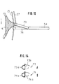
- An embodiment of the panty-hose closer shown in Figs. 12 to 14 assures more reliable seizure of the leg sections 1 and 2 by the suction holder units 30.
- the transferer assembly 50 of this embodiment includes a pair of suction guides 73 and 74 arranged between the panty closer and toe closer assemblies at the point of transfer. These suction guides 73 and 74 are properly secured to the pedestal of the device.
- the upper suction guide 73 has one end located close to the upper side leg section 1 of the incomplete panty-hose 5 at the point of transfer and the other end located close to the mouth of the suction tube 34 of the preceding suction holder unit 30 as best seen in Fig. 13.
- the lower suction guide 74 has one end located close to the lower side leg section 2 of the same incomplete panty-hose 5 and the other end located close to the mouth of the suction tube 34 of the following suction holder unit 30.
- the suction guides 73 and 74 have tubular sections 73a and 73b provided with longitudinal side slits, and movable lids 73b and 74b provisionally closing the side slits as shown in Fig. 14.
- the lids 73b and 74b open the side slits of the suction guides 73 and 74 so that the incomplete panty-hose 5 directly bridges the clamp holder unit 20 and the suction holder units 30.
- the incomplete panty-hose 5 is passed from the clamp holder unit 20 over to the suction holder units 30 by the above-described operation of the transferer assembly 50.
- a panty closer assembly is directly connected in operation to a toe closer assembly by assistance of a transferer assembly arranged at the junction so that transfer of incomplete panty-hoses can be carried out quite automatically for a continuous production of panty-hoses.
- the heart of the present invention resides in the process in which two leg sections of an incomplete panty-hose held by a clamp holder unit on a panty closer assembly are pneumatically and separately seized by two successive suction holder units on a toe closer assembly, and the panty section of the incomplete panty-hose is thereafter turned over and transferred to the suction holder units by operation of a transferer assembly which reciprocates between the panty closer and toe closer assemblies.
- panty and toe closers are quite separated from each other.
- direct connection between the two processes avoids the need for manual transportation of incomplete panty-hoses between panty and toe closers. These concur to assure efficient production and low production cost of panty-hoses.
Landscapes
- Engineering & Computer Science (AREA)
- Textile Engineering (AREA)
- Sewing Machines And Sewing (AREA)
- Socks And Pantyhose (AREA)
Description
- The present invention relates to an automatic continuous method for producing a panty-hose on a panty-hose closer which includes a panty closer assembly provided with a plurality of clamp holder units circulating along an endless first path of travel, a toe closer assembly provided with a plurality of suction holder units circulating along an endless second path of travel, and a transferer assembly arranged at a junction between the panty closer and toe closer assemblies.
- Furthermore, the invention relates to an automatic continuous panty-hose closer comprising a panty-hose closer assembly which includes a plurality of clamp holder units arranged for circulation along an endless first path of travel and is adapted for closing the panty section of a material panty-hose to form a incomplete panty-hose during the circulation of the clamp holder units, a toe closer assembly which includes a plurality of suction holder units arranged for circulation along an endless second path of travel and is adapted for closing the toe ends of the incomplete panty-hose to form a complete panty-hose during the circulation of the suction holder units, and a transferer assembly arranged at a junction between the panty closer and the toe closer assemblies.
- In the conventional production of a panty-hose, toe ends of the leg sections of a material panty-hose are closed on a toe closer while the panty section of the material panty-hose is closed on a panty closer, seperately. though either operation can be carried out first, closing of the toe ends usually precedes closing of the panty section due to the constructions of toe closers available on market.
- One example of such a panty closer is described in US-A-3 777 681, and one example of such a toe closer is described in US-A-4 133 280. Panty-hose closers are also known from US-A-3 520 262, GB-A-2 081 316, GB-A-2 103 257, and FR-A-2 415 684.
- The panty and toe closers are usually built as separate machines and usually a panty-hose production mill is equipped with a number of panty and toe closers. One closer requires one operator and additional operators are required for transportation of incomplete panty-hoses between panty and toe closers. Here, the words "an incomplete panty-hose" refers to a material panty-hose with a closed panty section when closing of the panty section comes first, and to a material panty-hose with closed toe ends when closing of the toe ends precedes. In either case, transportation of incomplete panty-hoses between panty and toe closers is highly labour and time consumptive, thereby seriously lowering efficiency in production of panty-hoses.
- It is the object of the present invention to provide a production system of panty-hoses which assures remarkable saving in labour and running costs at mills producing panty-hoses. In accordance with one aspect of the present invention, the method is carried out by mechanically holding one incomplete panty-hose on one clamp holder unit in a laterally spread state in which the sew line on its closed panty section should be substantially in line with the first path of travel of the clamp holder units and its open leg sections should be separately left free, seizing, while keeping the laterally spread state, the leg sections into a pair of successive suction holder units by application of pneumatic suction at the junction, releasing the incomplete panty-hose from the mechanical hold by the clamp holder unit while keeping the laterally spread state, catching the panty section of the incomplete panty-hose by the transferer assembly, and inserting the closed panty section of the incomplete panty-hose inside out over the suction holder units by reciprocation of the transferer assembly for fully automatic transfer of the incomplete panty-hose from the panty closer to the toe closer assembly.
- In accordance with the other aspect of the present invention, the panty-hose closer is characterized in that the junction is taken facing a station on the first path of travel for the clamp holder units whereat the incomplete panty-hose is mechanically held in a laterally spread state in which the sew line on its closed panty section is substantially in line with the first path of travel, that leg sections of the spread incomplete panty-hose held by the clamp unit in a free state are pneumatically seized separately by a pair of successive suction holder units arriving at the junction, that the transferer assembly catches the spread panty section of the incomplete panty-hose, that the clamp holder unit thereafter releases the spread incomplete panty-hose from its mechanical hold, and that the transferer assembly inserts the panty section of the incomplete panty-hose inside out over the suction holder units by its reciprocation for automatic transfer of the incomplete panty-hose from the panty closer to toe closer assembly.
- The invention will hereinafter be explained in more detail in reference to the accompanying drawings, in which;
- Fig. 1 is a plan view of one embodiment of the panty-hose closer in accordance with the present invention.
- Fig. 2 is a side view of the one embodiment of the clamp holder unit used for the panty closer assembly of the panty-hose closer in accordance with the present invention.
- Figs. 3A to 3D are perspective views of material, incomplete and complete panty-hoses processed on the panty-hose closer in accordance with the present invention,
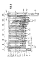
- Fig. 4 is a plan view for explaining the arrangements relating to the oval path of travel for suction holder units on the toe closer assembly,
- Fig. 5 is a plan view for showing operations applied to incomplete panty-hoses at different work stations on the oval path of travel for suction holder units on the toe closer assembly,
- Figs. 6 is a side view of one embodiment of the transferer assembly used for transfer of incomplete panty-hoses from the panty closer to toe closer assembly,
- Fig. 7 is a view seen in the direction of VII-VII in Fig. 6,
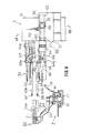
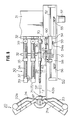
- Figs. 8 and 9 are plan views for showing the manner of incomplete panty-hose transfer on the panty-hose closer shown in Fig. 1,
- Figs. 10, 11A and 11B are perspective views for showing operation of the transfer assembly on the panty-hose closer shown in Fig. 1,
- Figs. 12 and 13 are plan and side views of the other embodiment of the panty-hose closer in accordance with the present invention, and
- Figs. 14A and 14B are transverse cross sectional views of suction guides used for the panty-hose closer shown in Figs. 12 and 13.
- One embodiment of the panty-hose closer in accordance with the present invention is shown in Fig. 1, in which the panty-hose closer includes a panty closer assembly P for closing the panty sections of an incomplete panty-hose, a toe closer assembly T arranged next to the panty closer section P and for closing toes in the leg sections of the incomplete panty-hose and a
transferer assembly 50 arranged facing the junction between the panty and toe closer assemblies P and T for periodical transfer of each incomplete panty-hose from the panty closer to toe closer assembly T. - The panty closer assembly P includes an endless, substantially
horizontal guide rail 11 which defines, in the case of the illustrated embodiment, a circular path of travel. A flat,circular carrier 12 is slidably coupled to theguide rail 11 and holds, viasupport arms 14, a substantially horizontal,circular guide pipe 13 which is larger in diameter than the above-describedguide rail 11. A plurality ofclamp holder units 20 are arranged on thecarrier 12 at substantially equal intervals for movement along the above-described path of travel as thecarrier 12 rotates. In the case of the illustrated embodiment, the panty closer assembly P includes six sets ofclamp holder units 20 of same construction. - One embodiment of the above-described
clamp holder unit 20 is illustrated in Fig. 2, in which theclamp holder unit 20 is provided with a pair ofsupport arms vertical shaft 25. Onesupport arm 23 carries, at its distal end, a pair of upper andlower clampers 21 a and 21 b whereas theother support arm 24 carries at its distal end a pair of upper andlower clampers support arms shaft 25 with the smallest center angle, theclampers 21a a and 21b are located substantially in parallel to theclampers clamp holder units 20. When thesupport arms shaft 25 with the largest center angle, theclampers 21a a and 21b are located substantially in alignment with theclampers clamp holder units 20. Further, in each pair, the upper andlower clampers 21 a and 21 b (or 22a and 22b) are movable to and from each other so that they can apply, in pressure contact with each other, a clamp on the panty section of an incomplete panty-hose mounted to the associatedclamp holder unit 20. - Each
clamp holder unit 20 travels, together with thecarrier 12 and theguide pipe 13, in a direction shown with an arrow "a" in Fig. 1 in order to be sequentially registered at one of six work stations A to F taken along the above-described path of travel at equal intervals. Since the panty closer unit P in the illustrated embodiment includes six sets ofclamp holder units 20, each of the six work stations A to F are occupied by one of the six sets ofclamp holder units 20. - As shown in Fig. 3A, a material panty-
hose 4 includes a pair ofleg sections toe ends 1 a and 2a still open and connected to each other at a section above the crotch which is later formed into apanty section 3 shown in Fig. 3C. - At the first work station A, a material panty-
hose 4 such as shown in Fig. 3A is mounted to eachclamp holder unit 20 of the panty closer assembly P in such a mannerthat oneleg section 1 should be inserted over theupper clampers 21a a and 22a whereas theother leg section 2 should be inserted over thelower clampers 21 b and 22b. In this state, theleg sections guide pipe 13. - A
cutter unit 16 is arranged centrally of the path of travel for theclamp holder units 20 and turns about its inner end in sychronism with the mov- ment of thecarrier 12. As theclamp holder unit 20 travels from the second work station B to the third work station C, thecutter unit 16 turns in the same direction and forms a cut in the crotch of the material panty-hose 4 as shown in Fig. 38. After formation of this cut, thearms support shaft 25 so that theclampers clamp holder units 20 and the cut edges should be exposed towards the center of the circular path of travel. - A
sewing machine 17 is arranged whilst facing from the inner side the circular path of travel for theclamp holder units 20. As theclamp holder unit 20 travels from the fourth work station Dtothefifth work station E, the upper and lower cut edges in the material panty-hose 4 are shown together by thesewing machine 17 in order to form an incomplete panty-hose 5 shown in Fig. 3C which includes apanty section 3 and a pair ofleg sections toe ends 1 a and 1 stiff open. - As the
clamp holder unit 20 with the incomplete panty-hose 5 travels from the fifth work station E to the sixth work station F, thesupport arms shaft 25 so that theclampers clamp holder units 20. - The toe closer assembly T is arranged facing the fifth work station E of the panty closer assembly P. More specifically, the toe closer assembly T is arranged so that, when a
clamp holder unit 20 with an incomplete panty-hose 5 of the panty closer assembly P arrives at the fifth work station E, at least two ofsuction holder units 30 of the toe closer assembly T should be located facing theclamp holder unit 20 of the panty closer assembly P. Before the moment whereat the twosuction holder units 30 face theclamp holder unit 20, the twoleg sections hose 5 held by theclamp holder unit 20 and hanging down from theguide pipe 13 are separately caught by thesesuction holder units 30. - As this seizure of the
leg sections suction holder units 30 should preferably be generated when theleg sections suction holder units 30. At this seizure by thesuction holder units 30, oneleg section 1 held by theupper clampers clamp holder unit 20 is caught by the precedingsuction holder unit 30 and theother leg section 2 held by thelower clampers 21b and 22b of theclamp holder unit 20 is caught by the followingsuction holder unit 30. - After the above-described preemptive seizure of the
leg sections hose 5 the successivesuction holder units 30 face theclamp holder unit 20 at the fifth work station E whereat theclamp holder unit 20 releases the incomplete panty-hose 5 and, concurrently with this release, thepanty section 3 is inserted inside out over theleg sections suction holder units 30 by operation of thetransferer assembly 50. As thesuction holder units 30 travel further move along a prescribed, endless path of travel on the toe closer assembly T, the toe ends 1a a and 1 b of the incomplete panty-hose 5 are shown in order to obtain a complete panty-hose 6 shown in Fig. 3D. - The toe
closer assembly 50 is shown in detail in Figs. 1, 4 and 5. A pair of spaced,oval frames 32 are mounted to the front side, i.e. the side facing the panty closer assembly P, of amagazine 31. Theframes 32 both extend vertically and substantially in parallel to each other in order to define an oval path of travel for thesuction holder units 30. In the case of the illustrated embodiment, 16 sets ofsuction holder units 30 are arranged along the oval path of travel at substantially equal intervals. As best seen in Figs. 4 and 5, eight work stations I to VIII are taken on the oval path of travel for operations to be applied to an incomplete panty-hose 5 carried by each pair ofsuction holder units 30. - Each
suction holder units 30 includes asuction tube 34 having afront suction head 33 and directed substantially normal to the oval path of travel for thesuction holder units 30, and intermediate andrear sliders suction tube 34. It further includes a pair offinger plates suction head 33 and extend along thesuction tube 34. Thesefinger plates intermediate slider 35. Therear slider 36 carries acircular disc 39 used for opening and closing the front ends of thefinger plates circular disc 39 in one direction and are closed upon rotation of the 39 in the other direction. Thefinger plates intermediate slider 35 and therear slider 36 form a unit which is movable to and from thesuction head 33 along thesuction tube 34. - As described already, the
suction holder units 30 are arranged along the oval path of travel defined between the pair offrames 32 and driven for intermittent movement in a direction shown with an arrow "b" in Fig. 4. Eight work stations I to VIII are taken along the oval path of travel for prescribed operations to be applied to an incomplete panty-hose 5 carried by eachsuction holder unit 30. - When an incomplete panty-
hose 5 carried by aclamp holder unit 20 arrives at the first work station I shown in Figs. 4 and 5, its twoleg sections guide pipe 13 are separately and pneumatically caught by a air of successivesuction holder units 30. More specifically, the upperside leg section 1 held by theupper clampers clamp holder unit 20 is caught by thesuction tube 34 of the precedingsuction holder unit 30 whereas, the lowerside leg section 2 held by thelower clampers 21b and 22b is caught by thesuction tube 34 of the followingsuction holder unit 30. This pneumatic seizure of the twolegs - A
first suction unit 40 is arranged facing the rear ends of thesuction holder units 30 passing by whilst extending from the first to second work station II as shown in Fig. 5 so that thesuction tubes 34 of thesuction holder units 30 travelling through this area are brought into pneumatic communication with thesuction unit 40. - With the suction on the
leg sections suction holder units 30 come to the second work station II and face theclamp holder unit 20 still holding thepanty section 3 of the incomplete panty-hose 5. At this moment, theclamp holder unit 20 cancels its hold on the incomplete panty-hose 5 and, as already described, thepanty section 3 is inserted inside out over the twosuction holder units 30 by operation of thetransferer assembly 50. Thus, at this second work station, II, the incomplete panty-hose 5 is fully transferred from the panty closer assembly P to the toe closer assembly T by assistance of thetransferer assembly 50. - The suction acting on the incomplete panty-
hose 5 is cancelled as thesuction holder units 30 travel from the second to third work station III. - At the third work station III, a pair of turn-over
rollers panty section 3 of the incomplete panty-hose 5 brought to this station. As the turn-overrollers panty section 3 is moved rearwards so that thepanty section 3 and theleg sections suction holder units 30. The toe ends 1a and 1b of the incomplete panty-hose 5 in this state are located near the front suction ends 33 of thesuction holder units 30. - Heel and toe position adjustments are conditionally carried at the fourth and fifth work stations IV and V. For correct seaming of a toe end of an incomplete panty-
hose 5, the heel end has to be located on the associatedsuction holder unit 30 so that it should come into exact alignment with the seam line of the associated toe end. - A pair of
heel adjusters 43 are arranged at the fourth work station IV and a pair oftoe adjusters 44 are arranged at the fifth work station V. Any conventional adjusters are usable for this purpose. One example of such an adjuster includes a photoelectric sensor, a comparator circuit, a pulse motor electrically connected to the comparator circuit, and and adjuster roller which is driven for rotation by the pulse motor and arranged for contact with an incomplete panty-hose 5 on thesuction holder unit 30. The photoelectric sensor detects the actual position of, for example, the toe end with respect to thefront suction head 33 of the associatedsuction holder unit 30 and generates a corresponding actual position signal, On receipt of this signal, the comparator circuit compares this actual position signal with a reference position signal which represents the correct position of the toe with respect to the above-describedfront suction head 33, and generates an operation signal corresponding to the difference between the actual and reference position signals. On receipt of this operation signal, the pulse motor drive the adjuster roller over a period enough to bring the toe end to the correct position represented by the above-described reference position signal. It should be understood by one skilled in the art that the position adjustments at the fourth and fifth work stations IV and V are both carried out only when the difference is obtained in the comparator circuit. - After the conditional position adjustments, the incomplete panty-
hose 5 carried by thesuction holder units 30 is brought to the sixth work station VI. Aplate cam 45 is secured horizontally to therear side frame 32 at a level able to come into contact with thecircular disc 39 of eachsuction holder unit 30 passing by. As thecircular disc 39 comes in contact with theplate cam 45, thefinger plates suction holder unit 30 swing horizontally outwards from each other in order to laterally spread the toe ends 1 a and 1 b of theleg section 1 on thesuction holder unit 30. Further, thefinger plates - A
sewing machine 46 is arranged at the seventh work station VIII facing thefront suction head 33 of thesuction holder unit 30 passing by. As the incomplete panty-hose 5 on thesuction holder units 30 passes through the seventh work station VII, the spread toe ends 1 a and 1b are closed by seaming by thesewing machine 46 in order to obtain a complete panty-hose 6 shown in Fig. 3D, in which the complete panty-hose 6 includes aclosed panty section 3 and a pair of toe closedleg sections - As the
suction holder units 30 travel from the seventh to eighth work station VII, thefinger plates - A
second suction unit 47 is arranged facing the rear ends of thesuction holder units 30 passing by in the area of the eight work station VIII so that thesuction tubes 34 of thesuction holder units 30 travelling through this area are brought into pneumatic communication with thesuction unit 47. By operation of thissuction unit 47, theleg sections hose 6 on thesuction holder units 30 are sucked into therespective suction tubes 34. A pair of turn-overrollers 48 are arranged at this work station VIII in order to again turn over the complete panty-hose 6 concurrently with the suction by thesuction tubes 34. After the complete panty-hose 6 is fully turned over on thesuction holder unit 30, the suction by thesecond suction unit 47 is cancelled. - A funnel shaped
suction pipe 49 is arranged at the eighth work station VIII facing thefront sucking head 33 of eachsuction holder unit 30 passing by. Thus, the complete panty-hose 6 on thesuction holder units 30 now released from suction by thesuction unit 47 is dismounted from thesuction holder units 30 by suction of thesuction pipe 49 for pneumatic transporation to the next process. - As briefly described already, each incomplete panty-
hose 5 is passed from the panty closer assembly P over to the toe closer assembly T by operation of thetransferer assembly 50. One embodiment of thetransfer assembly 50 is shown in Figs. 6 to 8. Thetransferer assembly 50 is attached to themagazine 31 to the toe closer assembly T whilst extending across the oval path of travel for thesuction holder units 30. - More specifically, the
transferer assembly 50 includes anelongated bracket 51 is secured to the side of the magazine and extends towards the panty closer assembly P. A pair of upper andlower guides bracket 51 and both extend in parallel to each other in the longitudinal direction of thebracket 51. These guides 52 and 53 carry aslide head 54 which reciprocates along them. A pair ofsprocket wheels bracket 51 being horizontally spaced from each other in order to carry anendless chain 58. Thesprocket wheels drive motor 57 operationally coupled to thesprocket wheel 55 via a suitable reduction gear. Aguide roller 59 is secured to one link of theendless chain 58 and engages with avertical groove 54a formed on the mating side of theslide head 54 on theguides endless chain 58 is driven for one way rotation by thedrive motor 57, theguide roller 59 travels along the course of theendless chain 58 in order to cause corresponding reciprocation of theslide head 54 on theguides - A
vertical plate 60 is secured atop theslide head 54 and carries, on one side thereof, anair cylinder 70 which is horizontally directed in the longitudinal direction of thebracket 51. A pair ofpins 61 and 62 are secured near the front end of theplate 60 whilst being vertically from each other, andbifurcate swing levers pins 61 and 62, respectively. Theupper swing lever 63 includes arear branch 63a extending upwards and rearwards and afront branch 63b extending horizontally forwards. Thelower swing lever 64 includes arear branch 64a extending downwards and rearwards and afront branch 64b extending horizontally forwards in a manner same as that of thefront branch 63b of theupper swing lever 63. Thefront branches rear branches 73a and 64a are pivotably coupled to the front end of thepiston rod 70a of theair cylinder 70 by means ofintermediate links - When the
air cylinder 70 operates to advance itspiston rod 70a, the swing levers 63 and 64 swing about thepins 61 and 62 on thevertical plate 60 so that their front ends moves towards and away from each other. In case of the embodiment shown in Fig. 6, the front ends of thebranches cooperative hooks hooks clamp holder unit 20 at the fifth work station E on the panty closer assembly P and with the mid-point between twosuction holder units 30 at the second work station II on the toe closer assembly T. - The
hooks slide head 54 moves forwards on theguides hooks slide head 54 moves rearwards on theguides hooks suction holder units 30 of the toe closer assembly T as shown with fantom lines. In other words, by operation of theair cylinder 70, thehooks - The incomplete panty-
hose 5 bridges theclamp holder unit 20 and thesuction holder units 30 at the junction between the panty closer and toe closer assemblies Pond T. When theclamp holder unit 20 and thesuction holder units 30 both arrive at the above-described junction, the pair ofhooks transferer assembly 50 turn towards each other in order to grip the open edge of thepanty section 3 of the incomplete panty-hose 5 held by theclamp holder unit 20. - Next the
clamp holder unit 20 released the incomplete panty-hose 5 from its mechanical hold and, by operation of theair cylinder 70, thefront branches levers panty section 3 of the incomplete panty-hose 5. While keeping this open state of thepanty section 3, thehooks panty section 3 are moved rearwards, by operation of theair cylinder 70, to the receded position RP so that thepanty section 3 is dismounted from theclamp holder unit 20 and inserted inside out over thesuction holder units 30 catching theleg sections hooks panty section 3, are moved forwards to the stand-by position SP with closing of thefront branches levers hose 5. - If the transfer of an
incomplete panty hose 5 would take place at the sixth work station F on the panty closer assembly P, thehooks transferer assembly 50 would have to be advanced to an advanced position AP located deep in the area between the clampers of the clamp holder unit -20, because at this station, thepanty section 3 of the incomplete panty-hose 5 would have to be held by clampers of aclamp holder unit 20 in a closed state. This mode of transfer would force thetransferer assembly 50 to reciprocate over a very long distance between the advance position AP and the receded position RP. - The
clamp holder units 20 on the panty closer assembly P may be driven for an intermittent movement from station to station along the circular path of travel. For more efficient production of panty-hoses, however, it is preferably that theclamp holder units 20 should be driven for a continuous movement along the path of travel. In this case, eachclamp holder unit 20 does not stop but just passes by the point of transfer between the panty closer and toe closer assemblies, and only a short time can be reserved for transfer of incomplete panty-hoses 5. In other words, thetransferer assembly 50 is required to complete its operation very swiftly. In order to enable such a swift operation, it is preferable to make the reciprocating distance of thetransferer assembly 50 as short as possible. - In the case of the embodiment shown in Fig. 1, transfer of incomplete panty-
hoses 5 is carried out at the fifth work station E on the panty closer assembly P in order to suffice the above-described requirement for a shorter reciprocating distance. At this work station, the clampers of theclamp holder unit 20 are yet kept in an open state as shown in Fig. 8 and, in this state, the open edges of thepanty section 3 of the incomplete panty-hose 5 is located, as shown in Fig. 9, closer to the positions of the associatedsuction holder units 30 than it would be possible at the sixth work station F. In this case, thetransferer assembly 50 is required to reciprocate only over a short distance between the advanced position AP and the receded position RP as shown in Fig. 8. - The panty closer assembly P includes an arcuate,
additional guide pipe 27 properly secured to the pedestal of the apparatus. Thisadditional guide pipe 27 extends horizontally from the second to fifth work station on the diametrally outer side of theguide pipe 13, and at a level somewhat higher than theguide pipe 13. In the area between the second and third work stations, theadditional guide pipe 27 is curved diametrally inwards and downwards towards aclamp holder unit 20 located at the second work station B. - At the first work station A, a material panty-
hose 4 is manually mounted to aclamp holder unit 20 with itsleg sections guide pipe 13. As theclamp holder unit 20 passes by the second work station B, the starting end of theadditional guide pipe 27 intrudes into the gap between the twoleg sections side leg section 1 hangs down from theadditional guide pipe 27 and the lowerside leg section 2 hangs down from theguide pipe 13. Due to the difference in diametral position and level, theleg sections - Operation of the
transferer unit 50 on the panty-hose closer shown in Fig. 1 is shown more in detail in Figs. 10, 11A and 11 B. In this case of Figs. 11 A and 11B, as a substitute for thehooks clampers clampers panty section 3 of the incomplete panty-hose 5 as shown in Figs. 10 and 11A. Next, theclampers panty section 3 as shown in Fig. 11 B. - In the case of the foregoing embodiments,
leg sections hose 5 hanging down from theguide pipe 13 or guidepipes suction tubes 34 of the successivesuction holder units 30. An embodiment of the panty-hose closer shown in Figs. 12 to 14 assures more reliable seizure of theleg sections suction holder units 30. More specifically, thetransferer assembly 50 of this embodiment includes a pair of suction guides 73 and 74 arranged between the panty closer and toe closer assemblies at the point of transfer. These suction guides 73 and 74 are properly secured to the pedestal of the device. Theupper suction guide 73 has one end located close to the upperside leg section 1 of the incomplete panty-hose 5 at the point of transfer and the other end located close to the mouth of thesuction tube 34 of the precedingsuction holder unit 30 as best seen in Fig. 13. Whereas, thelower suction guide 74 has one end located close to the lowerside leg section 2 of the same incomplete panty-hose 5 and the other end located close to the mouth of thesuction tube 34 of the followingsuction holder unit 30. The suction guides 73 and 74 havetubular sections 73a and 73b provided with longitudinal side slits, andmovable lids 73b and 74b provisionally closing the side slits as shown in Fig. 14. - As an incomplete panty-
hose 5 carried by aclamp holder unit 20 arrives at the point of transfer, suction is applied to the associatedsuction holder units 30 by operation of the first suction unit 40 (see Fig. 5) and the side slits of the suction guides 73 and 74 are provisionally closed at this moment by thelids 73b and 74b. As a consequence, theleg sections suction tubes 34 of thesuction holder units 30 via the suction guides 73 and 74 as shown in Fig. 13. Soon after this suction, thelids 73b and 74b open the side slits of the suction guides 73 and 74 so that the incomplete panty-hose 5 directly bridges theclamp holder unit 20 and thesuction holder units 30. In this state, the incomplete panty-hose 5 is passed from theclamp holder unit 20 over to thesuction holder units 30 by the above-described operation of thetransferer assembly 50. - As is clear from the foregoing description, in the production system of the present invention, a panty closer assembly is directly connected in operation to a toe closer assembly by assistance of a transferer assembly arranged at the junction so that transfer of incomplete panty-hoses can be carried out quite automatically for a continuous production of panty-hoses. More specifically, the heart of the present invention resides in the process in which two leg sections of an incomplete panty-hose held by a clamp holder unit on a panty closer assembly are pneumatically and separately seized by two successive suction holder units on a toe closer assembly, and the panty section of the incomplete panty-hose is thereafter turned over and transferred to the suction holder units by operation of a transferer assembly which reciprocates between the panty closer and toe closer assemblies.
- By employment of the production system of the present invention, the amount of labour can be reduced to about half of that needed in the conventional system in which panty and toe closers are quite separated from each other. In addition, the direct connection between the two processes avoids the need for manual transportation of incomplete panty-hoses between panty and toe closers. These concur to assure efficient production and low production cost of panty-hoses.
Claims (9)
Priority Applications (2)
| Application Number | Priority Date | Filing Date | Title |
|---|---|---|---|
| EP19830105383 EP0126800B1 (en) | 1983-05-31 | 1983-05-31 | An automatic, continuous method for producing a panty-hose and a panty-hose closer used therefor |
| DE8383105383T DE3375412D1 (en) | 1983-05-31 | 1983-05-31 | An automatic, continuous method for producing a panty-hose and a panty-hose closer used therefor |
Applications Claiming Priority (1)
| Application Number | Priority Date | Filing Date | Title |
|---|---|---|---|
| EP19830105383 EP0126800B1 (en) | 1983-05-31 | 1983-05-31 | An automatic, continuous method for producing a panty-hose and a panty-hose closer used therefor |
Publications (2)
| Publication Number | Publication Date |
|---|---|
| EP0126800A1 EP0126800A1 (en) | 1984-12-05 |
| EP0126800B1 true EP0126800B1 (en) | 1988-01-20 |
Family
ID=8190505
Family Applications (1)
| Application Number | Title | Priority Date | Filing Date |
|---|---|---|---|
| EP19830105383 Expired EP0126800B1 (en) | 1983-05-31 | 1983-05-31 | An automatic, continuous method for producing a panty-hose and a panty-hose closer used therefor |
Country Status (2)
| Country | Link |
|---|---|
| EP (1) | EP0126800B1 (en) |
| DE (1) | DE3375412D1 (en) |
Cited By (2)
| Publication number | Priority date | Publication date | Assignee | Title |
|---|---|---|---|---|
| DE3911856A1 (en) * | 1988-04-11 | 1989-10-19 | Takatori Corp | AUTOMATIC ATTACHMENT DEVICE FOR SOCKING PART OF SEMI-FINISHED TIGHTS |
| DE4036989A1 (en) * | 1989-11-30 | 1991-06-06 | Takatori Corp | DEVICE FOR THE AUTOMATIC POSITIONING OF PANTYHOSE MATERIAL IN A PANTYHOSE SEWING MACHINE |
Families Citing this family (11)
| Publication number | Priority date | Publication date | Assignee | Title |
|---|---|---|---|---|
| GB8409884D0 (en) * | 1984-04-17 | 1984-05-31 | Detexomat Machinery Ltd | Transporting fabric pieces |
| DE3506316A1 (en) * | 1985-02-22 | 1986-09-04 | Elbeo-Werke Gmbh, 8900 Augsburg | Apparatus for making tights |
| US4784070A (en) * | 1985-09-10 | 1988-11-15 | Detexomat Machinery Limited | Pantihose manufacture |
| EP0230724B1 (en) * | 1985-11-26 | 1992-04-15 | Detexomat Machinery Limited | Garment, e.g. hosiery transport apparatus, and method |
| IT1213803B (en) * | 1987-07-14 | 1990-01-05 | Solis Srl | METHOD AND MACHINE FOR THE AUTOMATIC TRANSFER OF TIGHTS AND SIMILAR MANUFACTURED FROM A STITCHING MACHINE TO AN IRONING MACHINE |
| GB8730199D0 (en) * | 1987-12-24 | 1988-02-03 | Detexomat Machinery Ltd | Hosiery toe closing method & apparatus |
| IT1395911B1 (en) * | 2009-09-29 | 2012-11-02 | Bicchierai S R L | DEVICE AND METHOD FOR THE SEWING OF CLOTHES OF CLOTHES AS STOCKINGS AND TIGHTS |
| IT1395910B1 (en) * | 2009-09-29 | 2012-11-02 | Bicchierai S R L | DEVICE FOR HANDLING BLADES OR SIDE FLAPS OF TUBES OF A TOE-CLOSER. |
| IT1395909B1 (en) * | 2009-09-29 | 2012-11-02 | Bicchierai S R L | EQUIPMENT AND METHOD FOR THE PRODUCTION OF TIGHTS |
| ITMI20121604A1 (en) * | 2012-09-26 | 2014-03-27 | Boggiani Renato S R L | EQUIPMENT AND PROCEDURE FOR THE PRODUCTION OF TIGHTS |
| ITMI20121775A1 (en) | 2012-10-19 | 2014-04-20 | Santoni & C Spa | METHOD AND APPARATUS FOR LOADING AND TRANSFERRING TUBULAR TEXTILE ARTICLES |
Family Cites Families (8)
| Publication number | Priority date | Publication date | Assignee | Title |
|---|---|---|---|---|
| US3520262A (en) * | 1967-08-23 | 1970-07-14 | Chadbourn Gotham Inc | Method and apparatus for closing stocking toes and putting stockings on boarding forms for processing |
| JPS4822773B1 (en) * | 1970-11-19 | 1973-07-09 | ||
| FI46749B (en) * | 1971-05-19 | 1973-02-28 | Norlyn Oy | |
| US3793649A (en) * | 1972-09-18 | 1974-02-26 | Kellwood Co | Process for preparing ladies{40 {11 seamless pantyhose |
| GB1542827A (en) * | 1976-10-26 | 1979-03-28 | Takatori Machinery Works Ltd | Automatic method and apparatus for closing a toe end of a hose utilizing a straight line stitch |
| IT7809326A0 (en) * | 1978-01-27 | 1978-01-27 | Chietti Giovanni | SEMI-AUTOMATIC EQUIPMENT FOR LOADING TUBULAR PRODUCTS FOR SOCKS OR SIMILAR ONTO SEWING MACHINES AND FOR OTHER USES |
| JPS5731891A (en) * | 1980-07-31 | 1982-02-20 | Sukeo Mori | Inserting fitting device for stocking cloth in end automatic sewing machine for seamless stocking |
| US4487546A (en) * | 1981-08-05 | 1984-12-11 | Savio & C. S.P.A. | Device for transferring tubular fabrics from support hangers to a rigid body and inverting the fabric |
-
1983
- 1983-05-31 EP EP19830105383 patent/EP0126800B1/en not_active Expired
- 1983-05-31 DE DE8383105383T patent/DE3375412D1/en not_active Expired
Cited By (2)
| Publication number | Priority date | Publication date | Assignee | Title |
|---|---|---|---|---|
| DE3911856A1 (en) * | 1988-04-11 | 1989-10-19 | Takatori Corp | AUTOMATIC ATTACHMENT DEVICE FOR SOCKING PART OF SEMI-FINISHED TIGHTS |
| DE4036989A1 (en) * | 1989-11-30 | 1991-06-06 | Takatori Corp | DEVICE FOR THE AUTOMATIC POSITIONING OF PANTYHOSE MATERIAL IN A PANTYHOSE SEWING MACHINE |
Also Published As
| Publication number | Publication date |
|---|---|
| DE3375412D1 (en) | 1988-02-25 |
| EP0126800A1 (en) | 1984-12-05 |
Similar Documents
| Publication | Publication Date | Title |
|---|---|---|
| EP0126800A1 (en) | An automatic, continuous method for producing a panty-hose and a panty-hose closer used therefor | |
| CA2045796C (en) | Material handling system | |
| EP0054060B1 (en) | Bird cutting plant | |
| US4153972A (en) | Vacuum poultry eviscerating apparatus | |
| US3886879A (en) | Shirt front assembly, method and apparatus | |
| US4133280A (en) | Automatic method and apparatus for closing a toe end of a hose utilizing a straight line stitch | |
| US3941069A (en) | Automatic method and apparatus for closing the toe of seamless hose | |
| CA2014081A1 (en) | Poultry processing apparatus and method | |
| US3802028A (en) | Method and apparatus for use in evisceration of poultry | |
| US4649838A (en) | Process and machine for sewing the toes of pantyhoses with feed from a machine for forming pantyhoses and with ejection suitable for a subsequent automated transfer of the product | |
| US3986231A (en) | Poultry processing method | |
| EP1222858A2 (en) | Method and device for processing a cluster of organs of a slaughtered animal | |
| CN111169993A (en) | Ear wire conveying device for mask production | |
| US3902221A (en) | Eviscerator apparatus and method | |
| US4620494A (en) | Conveyor for use in carrying leg parts of half made pantyhose in an integrated pantyhose sewing machine | |
| US4602710A (en) | Loading system for a toe closing assembly | |
| US4383490A (en) | Hosiery toe closing machine | |
| US4538534A (en) | Apparatus and method for processing hosiery blanks | |
| US4519327A (en) | Transfer machine for overturning a textile tubular element for the sewing of the edges thereof and for the subsequent re-overturning and discharging | |
| CN113246538A (en) | Multifunctional bag making machine with modular design | |
| US4004320A (en) | Apparatus for use in evisceration of poultry | |
| WO1985003092A1 (en) | Dual-chain sewing machine | |
| US4020775A (en) | Toe closing machine and method for panty hose | |
| CN213035309U (en) | Ear wire continuous welding equipment and mask production line for mask production | |
| EP0016437A1 (en) | Automatic seaming method and apparatus for gored panty-hoses |
Legal Events
| Date | Code | Title | Description |
|---|---|---|---|
| PUAI | Public reference made under article 153(3) epc to a published international application that has entered the european phase |
Free format text: ORIGINAL CODE: 0009012 |
|
| 17P | Request for examination filed |
Effective date: 19840731 |
|
| AK | Designated contracting states |
Designated state(s): AT BE CH DE FR GB IT LI LU NL SE |
|
| RBV | Designated contracting states (corrected) |
Designated state(s): DE FR GB IT |
|
| GRAA | (expected) grant |
Free format text: ORIGINAL CODE: 0009210 |
|
| AK | Designated contracting states |
Kind code of ref document: B1 Designated state(s): DE FR GB IT |
|
| ITF | It: translation for a ep patent filed | ||
| REF | Corresponds to: |
Ref document number: 3375412 Country of ref document: DE Date of ref document: 19880225 |
|
| ET | Fr: translation filed | ||
| PLBE | No opposition filed within time limit |
Free format text: ORIGINAL CODE: 0009261 |
|
| STAA | Information on the status of an ep patent application or granted ep patent |
Free format text: STATUS: NO OPPOSITION FILED WITHIN TIME LIMIT |
|
| 26N | No opposition filed | ||
| PGFP | Annual fee paid to national office [announced via postgrant information from national office to epo] |
Ref country code: DE Payment date: 19910410 Year of fee payment: 9 |
|
| PGFP | Annual fee paid to national office [announced via postgrant information from national office to epo] |
Ref country code: FR Payment date: 19910419 Year of fee payment: 9 |
|
| ITTA | It: last paid annual fee | ||
| PG25 | Lapsed in a contracting state [announced via postgrant information from national office to epo] |
Ref country code: FR Effective date: 19930129 |
|
| PG25 | Lapsed in a contracting state [announced via postgrant information from national office to epo] |
Ref country code: DE Effective date: 19930202 |
|
| REG | Reference to a national code |
Ref country code: FR Ref legal event code: ST |
|
| PGFP | Annual fee paid to national office [announced via postgrant information from national office to epo] |
Ref country code: GB Payment date: 19930521 Year of fee payment: 11 |
|
| PG25 | Lapsed in a contracting state [announced via postgrant information from national office to epo] |
Ref country code: GB Effective date: 19940531 |
|
| GBPC | Gb: european patent ceased through non-payment of renewal fee |
Effective date: 19940531 |